Intelligent Well Completions
World’s first multiple fiber-optic intelligent well
New developments in fiber-optic sensing enable complex well architectures to be equipped with an array of sensors that revolutionizes reservoirs management
Sigurd Erlandsen, Norsk Hydro, Gisle Vold and Graham D. Makin, Weatherford
In August 2002, Norsk Hydro ASA completed industry’s first installation of multiple fiber-optic pressure and temperature gauges in a single well, along with a distributed temperature sensing (DTS) fiber and a surface-operated, intelligent-completion flow-control device. The system was installed in Oseberg Øst (East) Well E-11C in the Norwegian sector of the North Sea. The operator says extensive knowledge of pressure conditions is imperative. To optimally control the field’s water injection program, operations depend on having precise knowledge about pressure conditions in the reservoir over an extended period.
The system comprised multiple fiber-optic pressure and temperature gauges, as well as a distributed temperature-sensing fiber. All of the fiber-optic sensors were from Weatherford, and they were run along with WellDynamics’ surface-operated, intelligent-completion flow-control system components.
Since installation, the downhole sensor arrays have provided data for daily production management, and will enable strategic reservoir management over the life of the field. Pressure and temperature gauges in E-11C provide continuous data from two producing zones, and the DTS sensing fiber gives temperature readings throughout the wellbore. A single, 14-in. fiber-optic cable transfers data to surface. The technology, its benefits and the completion procedure used to install it are described below.
FIBER OPTICS
For several years, Norsk Hydro has participated in R&D projects related to downhole instrumentation and intelligent well (IW) technology. Installation/testing of the dual fiber-optic pressure/temperature gauges in E-11C is part of the technology collaboration with Optoplan (recently acquired by Weatherford).
Optical fibers are a well-developed, high-bandwidth, low-loss transmission medium used extensively in a number of non-oilfield applications such as telecommunications. In the past few years, they have begun to gain acceptance as permanently installed downhole sensors, although trials were carried out as long ago as 1990.1
Fiber-optic sensors provide high data rates and high temperature capability; and they are passive, chemically inert, and inherently stable and immune to electromagnetic radiation. Optical technology initially brought new capabilities that allowed continuous thermal surveillance of reservoirs in the form of DTS. Initially conceived as a steamflood-monitoring tool, the technology has proven capable of being applied to multiple- point sensor applications to monitor a number of parameters in oil and gas producers, as well as water injectors. The strong E&P industry interest in optical sensors derives mainly from the expectation of a higher reliability than conventional gauges because of the absence of active electronics in the downhole device.2 The technology that these devices exploit was developed mainly for the telecommunications industry during the past 35 years.3
THE COMPLETION PLAN
Well E-11C presented a challenge to the completion engineering team. In addition to an exceptionally harsh downhole environment with high pressure/temperature, the oil well was to be completed, with production expected from two formations, the Ness and the Etive. Later, the field management plan called for E-11C to be converted to a water-injection well. To enable the ultimate dual purpose, the well completion design employed hydraulically operated sliding sleeves and zonal isolation equipment, Fig. 1.
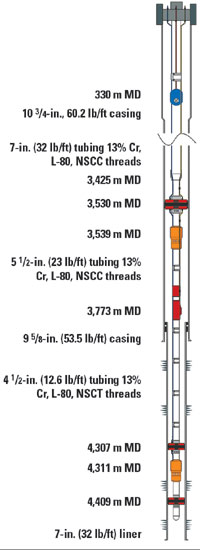 |
Fig. 1. E-11C completion diagram.
|
|
The pressure and temperature gauges and termination of the DTS line are located just above the liner hanger at a measured depth (MD) of 12,380 ft (3,773 m) and with a wellbore deviation of 73.2° The sensors are 771 ft (235 m) below the 9-5/8-in. production packer. Initial well pressure was 4,290 psi (289 bar) and producing temperature was 257°F (125°C).
Harsh, oilfield environments in general, and downhole temperatures specifically, have presented a fundamental challenge for conventional electronic gauges, whose failure rates are generally accepted to double with each 18°F (10°C) temperature increase. Since IW systems are essentially inaccessible once deployed, their value is directly linked to their longevity. For an IW to realize its true value, the permanent monitoring system must function for the life of that well. If downhole gauges fail prematurely, there is reduced benefit in having the ability to use in-well flow controls to adjust production flow profiles and optimize reservoir recovery later in field life.
Increased fiber-optic use is part of Hydro’s strategy for better well instrumentation. Hence the selection of Weatherford’s single-point, fiber-optic gauges which provide high reliability real-time measurements of wellbore temperature and pressure. The gauges are 100% optical, contain no moving parts, and are designed, tested, qualified and manufactured to ensure a long life in downhole environments.
Traditionally, the gauges are placed a joint above the production packer. However, for the E-11C application, traditional gauge placement would not have provided any monitoring of the uppermost formation. Further, it would not have accommodated DTS measurements in the well.
The completion team decided that ideal placement just above the liner top would allow monitoring of both formations individually and during commingling. Additionally, the DTS would pass both the gas lift mandrel and the upper inflow control valve.
Each gauge consists of a single, all-glass micro-structure sensing element, which was packaged into a transducer housing, Fig. 2. The transducer is rated for maximum continuous operating conditions at 320°F (160°C) and 20,000 psi. After connection of the gauges, a pressure test to 7,500 psi was conducted for 15 min. to verify sealing integrity.
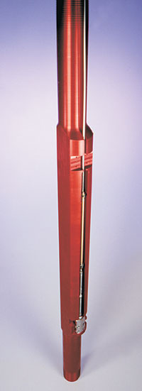 |
Fig. 2. Single-point fiber-optic pressure/temperature gauge.
|
|
A single fiber was dedicated for each of the two single-point pressure gauges. One sensor monitors tubing pressure, the other annular pressure. The gauges were attached to Weatherford’s 5-1/2-in. gauge carrier with metal-to-metal sealing backed-up with an elastomeric seal. The gauge carrier, Fig. 3, was machined from one piece of metal. It was 5.74 ft (1.75 m) long and weighed 23 lb/ft. The carrier was machined with NSCC threads and had special grooves to protect the control valve hydraulic lines.
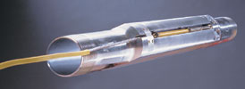 |
Fig. 3. Pressure gauges attached to downhole carrier.
|
|
The two fibers were encapsulated, through various layers, in a 1/4-in. tube with an 11 x 11-mm outer protective casing, Fig. 4. They were joined in a Y-coupling just above the gauge carrier.
From the coupling, a standard, single fiber-optic downhole cable comprised of three fibers was run 771 ft (235 m) to the 9-5/8 in. production packer. All cables were pre-installed through the packer. Fiber-optic dry mate connectors, installed at each end of the packer, aided quick connection offshore of a second length of fiber-optic cable, which was run 11,608 ft (3,538 m) from the production packer to the tubing hanger.
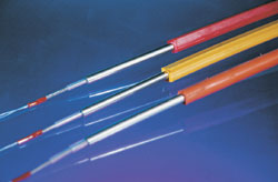 |
Fig. 4. Fiber-optic cable.
|
|
Two of the three fibers in the downhole cable were used to communicate with the single-point sensors. The third fiber was a multimode fiber used for DTS measurements. The DTS fiber was terminated in the Y-coupling and provides temperature readings from that point all the way to surface.
In all, five hydraulic lines and one fiber-optic line were run in hole. Four of the hydraulic lines were encapsulated in a flatpack. All six lines were fed individually through the tubing hanger. Four needle valves were required on the dry tree for proper feed of the six lines. Dual needle valves were used for the control valve lines.
Since fiber-optic systems only transmit light to retrieve the range of pressure/temperature parameters, they are 100% intrinsically safe. No sparks can be created. Hence, placement or routing of surface cabling from wellhead to the controlled environment of the data acquisition system does not require extraordinary planning.
RUNNING IN THE HOLE
The entire completion process offered numerous challenges and required considerable communication, pre-planning and staging between client and equipment/service providers. A large amount of downhole equipment was used in the completion, Fig. 5. Fifteen different sub-assemblies were attached to the tubing string. Three sizes of tubing were used and three different spooling units ran control lines in the hole.
 |
Fig. 5. Staging area just off of the rig floor.
|
|
The rig floor on Oseberg Øst is small, with no room for spooling unit placement. Hence, the spools were run from the pipe deck. Since the rig is an all-hydraulic Ram Rig system, there is no conventional drawworks, which made completion procedures even more challenging. The high degree of emphasis placed on safety by Norsk Hydro and the various service providers made an otherwise difficult physical environment work much easier.
When the gauge carrier was lifted onto the rig floor, 2,625 ft (800 m) of completion equipment had already been run. After coupling the carrier to the completion string, the two gauges were secured and pressure tested. The Y-coupling was then secured in a special collar for protection. A small spool located just outside the rig floor contained the first length of fiber cable, which was run up to the point of production packer placement. When reaching the production packer, it took about an hour to connect and test each of the two dry-mate connectors. From that point, the balance of the fiber cable was run from a larger spool located on the pipe deck.
A fiber-optic slip-ring/collector was attached to the spool. This enabled continuous monitoring of pressure/temperature gauges while running in hole. After the downhole fiber cable was cut to finished-length and fed through the tubing hanger, a landing splice was temporarily made to enable readout of the downhole sensors during setting/testing. The completion was safely landed within the expected time frame.
Later, a specially designed and certified wellhead outlet, which serves as a permanent barrier between well fluids and the controlled surface environment, was installed to interface downhole cables to surface cables that are connected to the acquisition unit. It was custom manufactured by Weatherford to customer specs, specifically to meet well requirements in terms of material, flange size, as well as pressure and temperature ratings.
THE SURFACE ACQUISITION UNIT
The optical gauges are the core in-well technology. However, to deliver a high-quality data stream, a systems approach is used, employing the downhole optical transducer along with the downhole fiber cable, the surface or wellhead outlet equipment and the surface data acquisition unit known as RMS2. To assure high reliability, the fiber-optics design approach has been to simplify in-well system components as much as possible. This results in a significant portion of the optical technology residing at the surface in the RMS2 unit as an electro-optical demodulation unit.
The RMS2 houses a keyboard and mouse for manual input, a flat panel display monitor, and all powering, signaling, processing and controls for the measurements. Since the “brains” of the fiber-optic IW technology system operate in a controlled environment at the surface, they are totally accessible and can be upgraded at any time. The RMS2 has its own uninterruptible power supply (UPS) and line conditioner that protects data in the event of power loss.
The surface system at Oseberg Øst consists of an optical demodulation unit that controls all downhole measurements. It provides a light source for downhole gauges, measures reflected wavelengths of light signals from downhole transducers, and converts them to engineering values using calibration files from proprietary software.
All data is stored on the local hard drive and coded with a date/time stamp. To provide quick access to archived data, a new logging file is created each day. Via the platform’s serial communications network, the data is transferred to a Siemens main frame computer system on the platform, then displayed in real time on screens in the platform’s control room. The data is used to assist decision making regarding daily control and optimization. Network connections enable onshore personnel to access the system for: change of logging rates, direct data download, and/or routine system checks.
GAINING CONTROL
Armed with reliable, real-time, downhole data and a reliable means of adjusting downhole flow-control devices, Norsk Hydro is now equipped to pro-actively adjust reservoir flow profiles to optimize production and enhance recovery over reservoir life. This will also be the case when the well is turned into a Water Alternating Gas (WAG) injector.
Applications of permanently installed pressure gauges are well documented, and the new-generation, fiber-optic pressure gauge is providing increased reliability and insensitivity to electromagnetic interference. It can be considered a direct higher-reliability and lower-drift replacement for its electrical equivalent, with a primary role in pressure buildup analysis and reservoir-pressure surveillance.
The first commercial installation of fiber-optic DTSs in oil wells occurred in California in 1995, where the ability of fiber to operate to temperatures exceeding 500°F (260°C) proved ideal for monitoring steamflood wells. To date, more than 100 steamflood wells have been instrumented with fiber-optic temperature-monitoring systems.
Because DTS measurements can be performed along the whole interval, monitoring flow contribution of individual zones enhances downhole permanent surveillance. The DTS can identify inflow intervals and zonal contribution over the whole reservoir interval. Because more wells are being drilled with long producing intervals and often are highly deviated or even horizontal, the cost of logging with production logging tools (PLTs) can be prohibitive. The DTS provides an alternative. In addition, while PLT logs capture data at a single point in time, DTS acquires data continuously. Events that may be difficult to interpret on a stand-alone basis can be correlated with surface production changes to identify changes in the downhole contribution.
For injection wells, a thermal analysis may be performed by use of the “warm-back” response of the reservoir, after it is shut in to determine relative injectivity of the individual zones. Although this data provides information only at the time of shut-in, economic effect of the shut-in is not as significant as for the case of a production well, and unplanned shut-ins provide free information.2
As well as improving reliability in monitoring reserves over life of the well, fiber optics enable a cost-effective way of installing an array of sensors, including non intrusive flow meters and in-well seismic arrays into the well on a single cable. Fiber-optic sensors provide day-to-day production management and enable enhanced strategic reservoir management over the course of its life.
The E-11C well was completed with no problems in the planned time frame. The gauges continue to provide vital real-time information regarding well performance. 
LITERATURE CITED
1 Lequime, M. et al., “Fiber-optic pressure and temperature sensor for downhole applications,” presented at the ECO-4 Conference on Optical Fiber Sensors, The Hague, March 14 – 15, 1991.
2 Brown, G. A. and A. Hartog, “Optical fiber sensors in upstream oil and gas,” Journal of Petroleum Technology, November 2002.
3 Optical fiber sensor technology, K.T.V. Grattan and B.T. Meggitt (eds.), Chapman & Hall, London, 1995.
THE AUTHORS
|
| |
Sigurd Erlandsen works in Norsk Hydro’s research center, with responsibility for R&D into intelligent wells. He joined Norsk in 1985 and has held various positions, including reservoir engineering group leader for the Visund development. He has an ME degree in petroleum engineering from Heriot-Watt University, 1985. He was an SPE distinguished lecturer for 2000/01.
|
|
Gisle Vold is a completion systems engineer for Weatherford International Ltd. His areas of expertise include developing, testing, marketing and selling a range of intelligent well systems, as well as providing project management for IW installations. He was responsible for project managing the world’s first multiple fiber-optic IW for Norsk Hydro. He holds EE and PE degrees from Rogaland University Centre.
|
| |
Graham D. Makin, marketing director, intelligent completions technologies, Weatherford International Ltd., is responsible for worldwide commercialization/marketing of IW technologies. He has been involved with Weatherford’s expansion into the IW market since 2000. In addition to sales and marketing, his 15 years in the industry includes working in various production, completion design and well servicing roles for BP and the former Aberdeen-based Petroline Wellsystems. He holds a mining engineering degree from Nottingham University.
|
|

