Offshore Report
Offshore LNG transfer and storage is set to fill the global gas gap
Recognizing that LNG will have to fill the gap in US gas supplies, several companies have worked to develop a suite of LNG near-shore and offshore transfer systems, as well as an offshore terminal design, that should bring the LNG market to a new threshold of capability
J. de Baan, Bluewater Energy Services B.V., M. H. Krekel and R. Leeuwenburgh, Bluewater Offshore Production Systems (USA), Inc.; and M. M. McCall, Conversion Gas Imports, LLC.
Given the world’s rapidly rising appetite for natural gas and resultant transportation needs, a family of “ship-to-ship” and “ship-to-shore” LNG transfer systems has been designed. These commonly designed systems can be varied for individual project configurations.
In conjunction with these systems, a near-shore LNG terminal has been designed. The systems described should greatly advance implementation of LNG offshore terminals. Although the systems are new, the components are proven and have been applied previously in LNG terminals and offshore loading systems.
INTRODUCTION
LNG is the world’s fastest growing hydrocarbon fuel. While gas usage as a primary fuel is forecast to grow at 3%, annually, in the next two decades, LNG as a subset is expected to grow at double that rate.1 LNG development has been encouraged by enormous amounts of stranded gas worldwide, a reduction in gas flaring, a “greening” of the energy mix and several gas price spikes.
The US is the world’s largest gas market, for which 85% of supply is produced domestically. The remaining 15% is imported, of which 98% is from Canada and only 2% is in LNG form. Although US demand should grow 2% per annum, the country’s gas production rate shows an accelerating, intrinsic decline – more newly discovered gas is needed each year to satisfy demand. As producers struggle to maintain output, LNG is poised to capture a portion of demand growth.
Political, financial and security concerns are slowing development of significant capacity increases for receiving LNG in the US and Europe. Accordingly, an offshore alternative to moor, unload, store and distribute gas sourced as LNG has been designed by Bluewater Energy Services and Conversion Gas Imports (CGI). It has the potential to be faster to build, less expensive, much more secure, and more acceptable to communities than conventional alternatives. The concept is bolstered by a recent US Department of Energy (DOE) study.
OFFSHORE TRANSFER OF LNG
LNG production and importation will increasingly move offshore. Given potential sites’ varied water depths and environmental conditions, a suite of transfer concepts has been developed, Fig. 1. These concepts’ common philosophy includes high system availability and suitability for non-dedicated vessels.
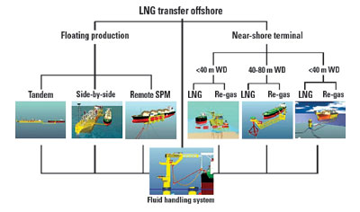 |
Fig. 1. This suite of LNG transfer systems shares a common philosophy of high system availability and is applicable to non-dedicated vessels.
|
|
High system availability. Investments made in LNG production and transportation are large, as are costs associated with LNG output downtime and/or demurrage of carriers. High system availability is achieved by using weathervaning mooring systems, robust flow paths and minimal, cryogenic mechanical components. All concepts are based upon proven components.
Suitability for non-dedicated vessels. Industry trends indicate that an LNG spot market is developing. Flexible, efficient terminal operation requires handling vessels of opportunity. Thus, LNG transfer in all systems takes place at the mid-ship manifold, requiring only minimal adaptation of the LNG carrier.
Near-shore terminal. Loading and offloading LNG requires terminals. At locations with deep water close to the coast, terminals may consist of jetty structures and breakwaters. There, tankers are moored, and offloading takes place via standard loading arms.
However, offshore terminals are attractive alternatives for less favorable conditions – shallow waters, congested shipping and/or mooring, difficult permitting and tough community acceptance. Although offshore facilities exist – they have been used widely to load oil and oil products for many years – no such terminals are used for LNG, yet.
Offshore LNG terminals offer lower construction and operating costs, the ability to locate a terminal in deeper water (eliminating the need for dredging and increased availability), safety and reduced voyage time (LNG carriers need not enter congested waters).
Bluewater and CGI have developed a series of LNG terminal concepts, based on the premise of safe LNG transfer offshore, to and from non-dedicated tankers in wave heights of up to Hs = 5.0 m and flowrates of up to 10,000 m3/hr (353,000 ft3/hr). Three near-shore concepts have been developed, including medium and shallow water terminals, and an offshore regasification dock.
Medium water terminal. Dubbed “Big Sweep,” this concept has three basic elements, Fig. 2.:
- A jacket structure with turntable, anchored to the seabed
- A submerged rigid arm, hinged at one end to the jacket turntable and terminating at the other end with a buoyant column
- LNG loading and transfer structure, on top of the buoyant column.
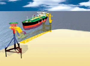 |
Fig. 2. The Big Sweep system has a jacket structure with turntable connected to a submerged rigid arm.
|
|
To allow the vessel and arm to weathervane passively into the most favorable direction, the turntable connects to the jacket structure via a bearing. This allows the turntable to rotate 360°.
The turntable supports rigid arm hinges, cryogenic fluid swivels and hawser attachment point. Optionally, a helicopter deck, control/monitoring room and regasification equipment can be mounted. Main rigid arm elements are:
- A hinge assembly that allows the loading arm to pitch and weathervane relative to the jacket structure
- A structural lattice forming a rigid arm
- A buoyant hull section that pierces the waterline and accommodates LNG offloading equipment.
The rigid arm’s overall length is such that the buoyant column is positioned nominally near the LNG carrier’s mid-ship cargo manifold. By adjusting the mooring hawser’s length, the carrier’s cargo manifold is lined up to the offloading station for sizes ranging from large to very large gas carriers.
The buoyant hull has a thruster system to swing the arm into a safe position while approaching the vessel and in line with the vessel during operations. A water ballast tank allows adjustment of the loading arm to match tanker size and/or drafts.
The standard fluid transfer system is three pipe-in-pipe (PIP) lines. Two lines are dedicated to LNG – either in full-flow or re-circulation mode. The third line is for vapor return. Flow paths cross the weathervaning and pitch hinges between the jacket and rigid arm. This is achieved with swivels and full metal jumpers.
The loading arm normally trails the jacket, but it can be temporarily “parked” away from the LNG carrier’s approach, with its own propulsion. In this position, the entire loading arm cannot be damaged by a carrier’s failed mooring approach. However, offshore tanker mooring to SPM systems is standard marine practice – a failed approach run very rarely happens.
The carrier moors in tandem with the turntable. Once it is secured and alignment is stable, the loading arm is deployed toward the vessel’s manifold. Hose deployment and loading are then initiated. After transfer completes, all of the steps just mentioned are done in reverse.
Emergency disconnection, following hawser failure or excessive positioning difficulties (e.g. fishtailing), takes place readily by:
- Quick disconnect, allowing for controlled closure of transfer system valves/pumps
- Activating full thruster power to clear the rigid arm away from the export tanker, returning it to a temporary parking position, giving the LNG carrier wide berth.
Due to the rigid arm’s relatively high mass and long length, the arm’s heave motions (pitch) are very small. This was validated in physical model tests, in significant wave heights to 9 m.
Shallow water depth terminal. Developed from the Big Sweep, this unit operates in 40-m water depths or less. It allows direct offshore-to-shore LNG transfer, at up to 10,000 m3/hr from non-dedicated vessels.
Motion characteristics allow offloading to proceed, up to significant wave heights of 3 m, depending on water depth (as little as 15 m). For extreme conditions, the unit’s free end is water-ballasted and set temporarily on the seabed.
Dynamic positioning (DP) allows the unit to follow the carrier manifold when loading or unloading. However, this drives the unit out of the way when the carrier is mooring itself to the jacket’s turntable, thereby avoiding marine hazards. Regasification equipment may be set on the unit for applications without LNG storage, as in gas stored in salt caverns or delivered directly to the onshore gas grid.
Offshore regasification dock. A floating dock concept is not new. However, when combined with reduced displacement, connected to a single-point mooring (SPM) system and fitted with a simple, redundant DP system, it can:
- Berth standard LNG vessels offshore
- Unload LNG through standard marine loading arms
- Allow transfers in conditions up to 4 m, significant wave height
- Provide a stable platform for a regasification plant
- Allow disconnection for dry-dock maintenance and/or modifications.
Essentially, the concept is based on permanently mooring a partly submerged dock, through an articulated rigid arm, to a catenary anchor leg buoy, Fig. 3.
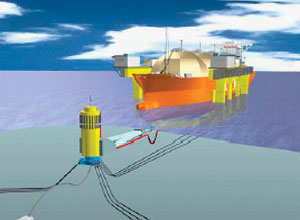 |
Fig. 3. The offshore regasification dock, a floating concept, moors a partly submerged dock through an articulated rigid arm to a catenary anchor leg buoy.
|
|
The articulated rigid arm allows the dock to take a sway/yaw position relative to the buoy. The concept has transverse propulsion integrated into the dock. When an LNG vessel moors on the SPM’s hawser messenger wire, and inches itself up to the buoy, the dock is able to track the LNG vessel’s path. Thus, the dock maintains sideways clearance with the vessel until it surfaces to contact the hull’s underside, once an approach is completed.
The amount of contact force is a function of operating environment, but its magnitude is such that no relative motions occur between vessel and dock. At all times, contact forces are modest and easily accepted by the vessel. Effectively, the vessel is fixed to the SPM through friction, only. This allows usage of standard marine loading arms.
Given the dock’s displacement, substantial load capacities can be handled to support a full regasification plant. This allows gas export (rather than LNG) to shore. The dock can also be released from the anchor chains and taken into a harbor/yard environment for major upgrades or overhauls. Relocating the unit to another location is also quite feasible.
Export from production barge. Companies are developing systems for floating LNG production and storage vessels (FLNGs).3 Successfully operating such systems requires safe, reliable LNG transfer to export vessels.
Transfer concepts are based on the traditional side-by-side configuration, or they require equipping the export vessel with propriety connection equipment. Both factors adversely influence terminal availability and flexibility, so a number of concepts have been developed to circumvent these drawbacks.
Tandem configuration. The Big Sweep concept is also deployable from an FLNG, Fig. 4. It enables offshore, ship-to-ship LNG in tandem mode, increasing overall availability. The concept has the same components, albeit a three-axis joint is provided on the arm’s FLNG side. Main differences between the two concepts are FLNG motions. These, in combination with the steady arm, result in higher structural loading. Operationally, both systems are comparable.
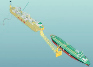 |
Fig. 4. Deployable from an FLNG, the Big Sweep tandem configuration is another form of offshore, ship-to-ship LNG transfer.
|
|
Model tests of this concept in MARIN’s offshore basin in the Netherlands confirmed workability in sea states up to 5 m, and survival conditions of 9 m, significant wave height. Moreover, DP station-keeping has been verified, with only modest power levels needed to maintain a “follow me” mode.
Side-by-side configuration. Another concept adapts the traditional side-by-side configuration to LNG transfer. Key features include:
- Increased safety distance between the FLNG barge and export vessel during transfer
- Easier mooring, fewer mooring lines and less personnel safety issues.
The concept works with a typical (short) low-sway/yaw, SPM-type hawser attached to a rigid arm’s end. This arm is mounted on a turntable fitted to the barge. Mooring elasticity is provided by a gas-hydraulic cylinder at the rigid arm’s short end. The arm can swing freely forward if the LNG carrier “nudges” it in that direction.
An aft fender arrangement, based on a pivotal support assembly, is near the end of the carrier’s flat side shell. This ensures that the “near position” (i.e. bending radius control) of the flexible-hose LNG transfer system is never compromised. Although no model tests have been performed, Bluewater believes that safe mooring in conditions up to 3.5 m, significant wave height, are practical.
Deepwater remote SPM dock. When LNG transfer in side-by-side or tandem mode poses unacceptable operational constraints, export to the LNG carrier is realized via a remote, single-point moored dock, Fig. 5. The system is similar to the offshore dock described previously but without the regasification plant. It is at a safe distance from the FLNG, typically 1 nautical mile.
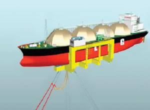 |
Fig. 5. Perfect for deep water, this remote, single-point moored dock excludes a regasification plant that is kept a safe distance (one nautical mile or more) from the FLNG vessel.
|
|
Product transfer from the FLNG to the SPM dock is via submerged, full-metal PIP lines. Transfer lines are suspended via short chain sections from the SPM, with jumpers forming the final connection to the dock’s piping. This effectively decouples the SPM dock’s dynamic rotations from PIP transfer lines, reducing fatigue damage.
Fluid handling system. Offloading equipment is configured as a “manipulator,” from which the free end of steel, articulated loading arms or flexible catenary hoses is suspended, Fig. 6. This configuration is advantageous, allowing the free ends (3 x 20 in.) to be combined into a single assembly handled by direct mechanical means. Individual hose connections, although technically feasible, would lead to clash potential during high-offset emergency disconnects and require more manpower for first-line connections.
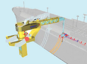 |
Fig. 6. Offloading equipment for the LNG transfer systems is configured as a manipulator assembly.
|
|
The manipulator’s principle is based on supporting the flowlines’ (flexible or rigid) free end from a tension leg. This maintains slight, vertical tension on the vessel interface while fully accommodating low-frequency heave of the Big Sweep, and the heave, pitch and roll of the LNG carrier. Tension is generated by a counterweight that moves in the fore-aft direction as a function of the stroking out of the horizontal boom. A redundant load pin measures actual tension in the tension leg and automatically adjusts the counterweight position.
When the tension leg experiences an angle of tilt, due to relative motions between Big Sweep and the carrier, that angle is automatically detected. The manipulator horizontal boom length and azimuth angle are automatically adjusted to bring back the angular value below a pre-set figure (<10°).
Loads on the manipulator assembly are of the same magnitude as normal offshore cranes. Since high-frequency motions do not affect positioning demands, power requirements are low. Beyond the pre-set limits, the tension leg automatically initiates disconnect, whereby the connector part is lifted up and away from the carrier.
Structural and multi-path flow components comprise the connector in the tension leg’s lower portion. All connectors are made up of standard, commercial components. The structural connector is attached first. Once it is secured, the flowpath connectors are stroked out to make up the connection. The structural connector is winched down against the tension leg’s slight over-pull. This allows the “first line” connection to be made in-phase and avoid impact loads in case of large LNG carrier rolls.
The manipulator concept allows automation of functions, enhancing safety and limiting manpower demand.
CASE STUDY: LNG TERMINAL OFFSHORE GULF OF MEXICO
DOE’s cooperative research project, which constitutes this article’s case study, sought to define, describe and validate salt cavern utilization to receive and store LNG cargoes. The process is defined as receiving LNG from a ship, pumping the LNG up to cavern injection pressures, warming it to cavern-compatible temperatures, injecting the warmed vapor into salt storage caverns, and distributing the gas to pipelines.
Work performed under this agreement is based on U.S. Patent 5,511,905, and other US and foreign patent-pending applications. The study’s cost-sharing participants are National Energy Technology Laboratory (DOE), BP America Production Co., Bluewater Offshore Production Systems (U.S.A.), Inc., and HNG Storage, L.P.
Initial results indicate that a salt cavern-based receiving terminal could be built at about half the capital cost and less than half the operating costs of a liquid tank-based facility. It would have significantly higher delivery capacity and shorter construction time, and be more secure. Significant knowledge and practice concerning natural gas storage in salt caverns exists, as well as for LNG handling. However, there has never been an attempt to develop a process that combines the two technologies.
Validation of an offshore, Gulf of Mexico, LNG receiving concept has profound implications for next-generation LNG terminals. Salt cavern LNG receiving terminals can be built quickly to provide additional import capacity into the US, exceeding 6 to 10 Bcfd in the aggregate.
Conventional, tank-based LNG receiving facility. A typical, conventional facility stores two to three ships’ cargoes, or about 5 to 8 Bcf of gas at standard conditions (250,000 to 380,000 m3 in liquid form). The terminal always has some LNG inventory in its storage tanks to keep everything cooled down. Typically, high-pressure pumps and vaporizers limit send-out. While the facility receives a cargo in 24 hr, it requires three to six days to discharge that volume as gas to pipelines.
Four LNG terminals in the US are of this design, including one being refurbished. All have expansion plans, but, collectively, their anticipated capacities fall far short of projected LNG imports by 2020. Various alternative designs – cryogenic tank storage on floating vessels, shipboard regasification units or gravity-based structures – generally take this model and move it to sea.
LNG cryogenic storage tanks are expensive to build and maintain. Further, cryogenic tanks are on the surface and present a tempting terrorist target. There is a need for a more secure, more economical and higher capacity method to receive, store and distribute LNG.
Cavern-based LNG receiving facility. Application of salt cavern storage technology, augmented by new pump technology, heat exchangers and facility design, could marry LNG and salt caverns into a secure, economical and flexible method to expand gas supplies. Underground hydrocarbon storage is inherently secure, as evidenced by the Strategic Petroleum Reserve’s (SPR’s) storage of more than 600 million bbl of oil. A salt cavern-based LNG receiving terminal provides far more storage capacity and “send out” capability than conventional facilities.
Two key differences between cavern- and tank-based facilities are that caverns can be miles from offloading facilities, and there is limited cryogenic liquid on site, absent a ship. At a conventional terminal, storage tanks must be close to the ship discharge site, and considerable inventory is maintained between ship calls.
At numerous salt formations, offshore, near-shore and close to navigable waters, caverns could be washed and developed into LNG terminals. Salt cavern gas storage has high deliverability that is instantaneously available to pipelines, far higher than LNG vaporization volumes in conventional terminals.
To illustrate the potential, consider a case study, where a marine terminal receives LNG from tankers. From there, LNG is transferred to the injection platform, where it is regasified and injected into the storage cavern.
The injection platform has a seawater lift system; seawater is used as a warming agent for regasification. The injection platform also accommodates a power generation plant fitted with a waste heat recovery unit (WHRU, to boost seawater temperature), and living quarters. Gas receipt and send-out to connecting pipelines is controlled from the platform. A typical field layout is shown in Fig. 7.
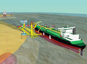 |
Fig. 7. This typical field layout incorporates LNG salt cavern storage and a shallow water version of the Big Sweep transfer system.
|
|
Critical elements. Major elements revealed in the cooperative study are:
- Salt formations suitable for cavern development
- Pipeline infrastructure sufficient to carry large gas volumes to market
- A method to moor and offload an LNG carrier and boost LNG to storage cavern injection pressures at volumes that allow acceptable ship discharge times
- A heat exchanger design that economically warms LNG at high pressure and high volumes.
Salt formations, storage location. This case study places the storage facility in Vermilion Block 179, a well-known salt formation in 100-ft water. This is sufficient for the draft of any known or planned LNG carrier.
Rights to develop salt cavern storage in US waters are obtained via lease from the Minerals Management Service. This case study looked at developing six caverns, each initially at 2 million bbl of capacity, able to hold about 12 Bcf of dense-phase gas at 2,000 psi. They could be developed and placed in operation within 12 months, and subsequently enlarged to 4 million bbl, each, for a total 24-Bcf capacity at an additional cost of less than $2 million. Larger caverns with increased capacity are feasible.
More than 300 known salt domes and countless acres of salt strata are in the US, many offshore. Salt domes, pillows or thick salt strata suitable for developing storage caverns also exist in other areas, including Mexico, northeastern Brazil, Europe and China.
Salt cavern storage is a proven, well-established technique. The drilling program, casing requirements, solution mining techniques, monitoring, logging and testing are all well-developed practices. Permitting by MMS is likely to follow practices used by state agencies that allow these facilities. Discharge of saturated brine created by solution mining at sea is permitted and practiced in the US, and in several other countries.
When fresh water or seawater is injected into salt formations, it dissolves and creates brine that is returned to the surface. The more water that is injected into salt formations, the larger the caverns become. The top of Vermilion Block 179’s salt formation is at depths of less than 1,000 ft, with a horizontal extent of more than 1 mi.
A salt cavern is an elongated chamber that can run to 1,500 ft in length, with capacity varying between 3 million and 15 million bbl. The largest cavern is about 40 million bbl, in crude oil service for the SPR. Each cavern must be fully surrounded by the salt formation so that nothing escapes to surrounding strata or another cavern. A single salt dome typically contains multiple caverns.
More than 1,000 salt caverns in the US and Canada store hydrocarbons exceeding 1.2 billion bbl. Explorationists have known Gulf of Mexico salt formation locations for some time, because of their interest in oil accumulations on the salt dome flanks and sub-salt.
Pipelines. The case study connects a salt cavern-based LNG receiving facility to three, large, Gulf of Mexico natural gas systems – Bluewater, Sea Robin and Texas Eastern. There is take-away capacity of about 2 Bcfd available in these systems. Looping or extending connections to additional systems could expand capacity.
The Gulf of Mexico’s extensive oil and gas pipeline network moves close to 15 Bcfgd onshore. Additional capacity is estimated at 5 Bcfgd, enough to move imported LNG from storage to market. During DOE’s research project, more than 20 potential sites were evaluated. They feature salt formations suitable for storage cavern development in proximity to existing pipelines. Vermilion Block 179 was selected for this study, but there are many attractive sites.
Marine terminal. The case study selected a shallow water depth terminal as the most suitable concept. Transfer from a ship’s manifold to a weathervaning arm is via two cryogenic flexible hoses supplemented by a vapor return hose. On the fixed jacket, a series of pumps boosts LNG from the ship’s discharge pressure (about 50 psi) to the storage cavern pressure (2,000 psi), Fig. 8. This allows cryogenic hoses and swivels to have low-pressure ratings. Pump power is provided from the injection platform via high-voltage, subsea cable. A small regasification plant on the arm allows vapor return to the LNG carrier.
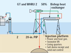 |
Fig. 8. At a shallow-water terminal, LNG is transferred from ships to the storage cavern via a series of pressure boosts and is warmed by a Bishop Process heat exchanger.
|
|
The high-pressure pump proposed does not cross technological barriers from those in common use at lower pressures (1,400 psi). Pump capacity is limited by driver power requirements to about 2,000 hp, each. Unloading rates in the range of 8,000 to 10,000 m3/hr are achievable with multiple pumps and are the basis for the case study facility.
LNG is pumped to the injection platform, about 1 nautical mile away, via two 20-in., PIP, cryogenic subsea flowlines. Their design is based primarily on (thermal) stress considerations, and not so much on thermal efficiency, when the LNG is regasified.
LNG heat exchangers. Conventional heat exchanger designs can warm high-pressure LNG. However, capacity limitations and energy consumption dictated a new approach – the patented Bishop Process heat exchanger.
The Bishop Process uses seawater to warm LNG and stores the resulting dense-phase gas in a salt cavern, or discharges it to a pipeline, or both. The volume ratio of seawater to LNG, the number of seawater injection points and the preheating of seawater and/or LNG can be determined on a site-specific basis.
To accomplish heat exchange in a horizontal flow configuration like the Bishop Process, the cold fluid must be kept at a temperature and pressure that maintain it in the dense or critical phase. This ensures that no phase change takes place in the cold fluid during its warming to the desired temperature. It also eliminates problems associated with two-phase flow, such as stratification, cavitation and vapor lock.
Dense or critical phase is defined as a fluid’s state, when it is outside the two-phase envelope of its pressure-enthalpy phase diagram. In this condition, there is no distinction between liquid and gas, and density changes during warming are gradual, with no phase change. This allows the heat exchanger to reduce or avoid problems with two-phase gas-liquid flows. The effect of confining the fluid to the dense phase is illustrated by an analysis of the densimetric Froude Number F that defines flow regimes for layered or stratified flows:
In this equation, V is fluid velocity, g is acceleration due to gravity, D is the pipe diameter, g is fluid density and Dg is the change in fluid density. If F is large, the terms involving stratification in the fluid motion governing equation drop out of the equation. As a practical example, two-phase flows in enclosed systems generally lose all stratification when the Froude Number rises to between 1 and 2. In this application, the Froude Number ranges in the hundreds, assuring complete mixing of any density variations. These high values occur because, in dense phase flow, the term Dg/g in the above equation is small.
Measurement of the Froude Number occurs downstream of the high-pressure pumps and in the heat exchangers. Process simulations using HYSIS and finite element modeling, conducted during the research, show that heat exchange occurs as predicted, icing is controlled and energy consumption is significantly lower than that experienced in liquid tank terminals.
Facility operations. A ship’s discharged LNG is delivered to the high-pressure pumps’ inlet at around 50 psi and -260°F, at rates between 8,000 and 10,000 m3/hr. High-pressure pumps boost the LNG to about 2,000 psi and discharge it to the heat exchangers.
Discharge temperatures from the pumps to the heat exchangers are higher than inlet temperatures and are considered in the design. Seawater is introduced into the heat exchangers in a counter-flow manner. Resultant discharge of dense-phase natural gas is at 2,000 psi and design temperatures of 40°+ F.
Cryogenic tolerance and expansion considerations are accommodated by metallurgy and mechanical design. Generally, the volumetric difference between LNG at atmospheric pressure and dense-phase gas, at 2,000 psi and 40°F, is one to three, so there is a velocity increase during warming, and the piping and cavern design account for this expansion.
Dense-phase gas is injected directly into the caverns and/or connecting pipelines. Once unloading completes, the entire cargo is handled at one time, leaving only enough on-site LNG to maintain the pumps in a cryogenic state. Operation, maintenance and inspection of LNG storage caverns are identical to practices in the 100-plus gas storage caverns operating in North America and Europe. However, the injection rate into LNG receiving caverns is high compared to conventional gas storage. The latter caverns use compressors to boost inlet gas pressure to rates generally between 0.5 and 1 Bcfd. The LNG application has injection rates of 3 to 4 Bcfd, accommodated by multiple caverns and wells.
Significant energy savings occur in pumping LNG, compared to compressing natural gas. A geo-mechanical temperature and rock mechanic analysis conducted as part of the research project indicates that cavern injections and withdrawals at the design rates described are within salt tolerances. 
ACKNOWLEDGEMENT
This article is adapted from OTC Paper 15301, presented at OTC 2003, Houston, May 5-8, 2003. Thanks are given to the US Department of Energy and its agencies, the Strategic Gas Center and the National Energy Technology Laboratory, for commissioning the cooperative research agreement under which this work was done. Thanks also go to the funding participants – BP America Production Co., Bluewater Offshore Production Systems (U.S.A.), Inc., and HNG Storage, L.P. In addition, cooperation and assistance was provided by the Federal Energy Regulatory Commission, the Minerals Management Service and the US Coast Guard.
REFERENCES
1 Merrill Lynch, Global Octane – Chapter 9, “Global LNG: a High Growth Market,” Oct. 23, 2002.
2 Stephan Schubarth, “U.S. Gas Market Recent Dynamics,” presentation to SPE Houston West Side Study Group, January 2003.
3 F. Faber, et al, “Floating LNG Solutions – from Drawing Board to Reality,” OTC Paper 14100, presented at the OTC 2002, Houston, May 6 – 9, 2002.
THE AUTHORS
|
 |
Jaap de Baan, vice president, technology and development, has been with Bluewater since its inception in 1978, and has been involved in the development and engineering of most of the firm’s products. Prior to working for Bluewater, he worked with IHC Holland and SBM in the offshore mooring terminals business. He holds a number of patents and originated the first “soft yoke FSO mooring system,” and the so-called “3x3 anchoring system,” both Bluewater developments. Mr. de Baan is now responsible for technical proposals and cost estimates for FPSOs and single-point mooring systems, as well as heading the development of new technology. He studied mechanical engineering at HTS Rotterdam, The Netherlands.
|
 |
Max Krekel, senior naval architect, hull and marine systems, has been with Bluewater since 1986 in various positions. He was responsible for the conversion engineering of the FPSOs Uisge Gorm and Glas Dowr, and has been closely involved with a number of joint industry projects on FPSO design and operation. Since mid-2001, he has been based in Houston to support Bluewater’s business development activities in Houston. Mr. Krekel holds a BSc in naval architecture from HTS Haarlem, The Netherlands.
|
 |
Richard Leeuwenburgh, senior naval architect, mooring and risers, began working for Bluewater at the corporate office in The Netherlands in 1994. He has been involved in a number of mooring and riser designs for FPSOs and CALM buoys. Since mid-2001, Mr. Leeuwenburgh has been based in Houston to give technical support to the firm’s business development activities in the US. He studied at Delft University of Technology and obtained an MS in marine technology.
|
 |
Michael M. McCall is President & CEO, Conversion Gas Imports, L.L.C., based in Houston. He founded the firm to commercialize technologies that lower costs and improve security in the receipt, storage and distribution of LNG, NGLs and olefins. He is a logistician with more than 30 years of experience in North and South America in the natural gas, NGL and petrochemical industries. He holds a BS in industrial distribution from Texas A&M University, and an MBA from the University of Chicago.
|
|

