Canyon Express: Completions for Aconcagua and Camden Hills fields
Offshore ReportCanyon Express: Well completions for six high-rate deepwater gas producersDownhole completion designs for six wells in two ultra-deepwater gas fields in the Gulf of Mexico Canyon Express project are discussed, including team planning, equipment details and successful use of the Discoverer Spirit drillship for the installationJ. Piedras, Total E&P, USA, Inc.; G.P. Stimatz, Marathon Oil Co.; V.B. Jackson Nielsen, WellDynamics, Inc.; and G.M. Watson, Schlumberger Subsea well completion design and implementation in Total’s (formerly TotalFinaElf’s) Aconcagua field and Marathon Oil Co.’s Camden Hills field posed unprecedented challenges. Water depths in the area of planned development (up to 7,209 ft) were greater than for any well previously completed in the world. Limited gas reserves in this high-cost, deepwater environment precluded future economic intervention, so the completion design had to balance the potential complexity of multiple-zone production with high life-of-well reliability. Conducting the completions from a dynamically positioned (DP) drilling vessel – which had not yet been done at the time completion planning was underway – presented additional challenges. The extensive pre-planning, preparation for contingencies (for both installation and production phases), and applications of the basic completion designs are presented here. This article was prepared from paper OTC 15094,1 written by the above authors and presented at the 2003 Offshore Technology Conference as part of a special session on the Canyon Express Project. Other relevant presentations from this session are noted within the following discussion. INTRODUCTION The Aconcagua field (Mississippi Canyon Block 305) is located in the Gulf of Mexico, about 140 miles southeast of New Orleans, Fig. 1. The Camden Hills field is located in an adjacent block (Mississippi Canyon 348). These fields, along with BP-operated King’s Peak field, produce into the Canyon Express gathering and processing system.2 Produced gas from subsea wells in all three fields is conveyed 55 mi via dual pipelines to the host processing platform operated by Williams Energy Services, located in Main Pass Block 261 and known as Canyon Station. The well completion budget comprised about 50% of total project cost.
The producing reservoirs are a series of high-permeability, unconsolidated sands, underlain in several cases by water-bearing sands. Well, rock and fluid data are summarized in Table 1. Experience has shown that wells completed in reservoirs of this nature will water-out quickly, once water production begins. Ability to drain the multiple gas sands and shut-off water production without intervention was a key driver of the completion design.
Design of the high-rate, deepwater gas producers eventually came to include stacked frac-pack sand control, pressure-operated fluid-loss/well control devices, and intelligent well completion equipment, with cleanup flow to temporary facilities on the rig. Completion work was conducted over a nine-month installation campaign from a dual-derrick DP drillship. Significant challenges were met and overcome, and numerous “firsts” for both the operators and the industry were established. Development of Aconcagua and Camden Hills consisted of batch completion of six predrilled gas wells. Completion work was conducted from the Transocean Discoverer Spirit drillship between January and September 2002. Production startup occurred just after the sixth completion, and all wells are capable of producing at or above design rates (50 MMcfd per well). Of equal importance to the well performance is the fact that all rig operations were conducted with a flawless safety and environmental record. No lost-time or OSHA-recordable incidents, environmental incidents, or Minerals Management Service incidents of noncompliance were incurred. Although the focus of this article is on the downhole equipment and installations, some relevant rig operations are discussed. More rig details are presented in the original paper.1 PLANNING AND EXECUTION A team approach was applied because of the tight economics of the field developments and scarcity of available personnel resources within each company, Total and Marathon agreed on a unique personnel-sharing arrangement. A joint group called the Wells Integrated Project Team (WIPT) was formed for the subsea tree installation and well completion design/implementation. Marathon had no financial interest in Aconcagua, and Total (prior to acquisition of Elf by TotalFina) had no financial interest in Camden Hills. The joint Total/Marathon efforts to complete wells in both fields allowed sharing of: 1) a common rig; 2) critical equipment (workover control system, subsea completion tree, etc.); and 3) a common well design, i.e., same subsea trees, same procedures, and common spare equipment. It also allowed combining the engineering staff (not only available manpower, but respective expertise). The WIPT was charged with designing an optimum completion, preparing procedures and providing technical rig supervision for the following operations:
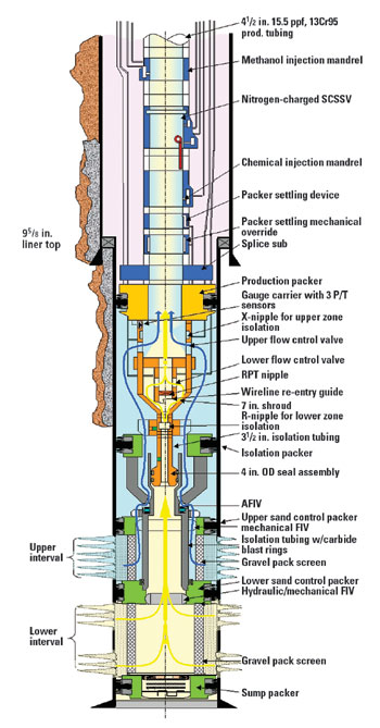
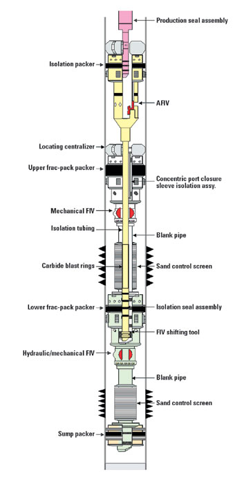
For the completion rig, four months before the planned start of rig operations, the Discoverer Spirit was selected to conduct the completion operations. This was a change from the rig that previously had been identified for use in this campaign. At this late stage, the rig change had tremendous trickle-down effects on completion preparation, since many of the procedures and much of the equipment are rig-specific. Significant rig modifications (primarily related to subsea tree and IWOCS handling and well test/flare equipment) were designed and implemented. The Spirit turned out to be very well suited for conducting the well completion work.1 The rig is a state-of-the-art dual-derrick drillship with ample deck space for accommodating the support equipment of numerous service companies. Few other rigs would have been capable of accommodating the nearly 200 personnel required during peak operations, or would have been able to rack back the multiple strings of pipe that were used. The flexibility afforded by the rig and its crew were key contributors to the project’s success. The rig’s marine crew carefully coordinated work with pipeline and umbilical lay vessels, another drillship, and a dive-support vessel which were at times active in the area during completion operations.3,4 Despite occasional difficulties, significant schedule improvement was noted as the completion program progressed. The entire six-well program was completed in 241 days of rig time, including 35 days for an aborted first attempt to complete MC305 2 and 18 additional days to sidetrack this well. Despite this major setback, the duration of the entire program was in line with the pre-campaign estimate of 240 days. As noted in the cumulative completion times in Table 2, the last four completions averaged 28 days each, 30% better than the initial estimate, the industry average for the most closely analogous completions had been about 50 days. All wells except MC305 2 were completed at or significantly below budget estimate. SUBSEA TREE INSTALLATION The WIPT took responsibility for the subsea trees from the Canyon Express Project Team after final quality assurance/quality control (QA/QC) and system integration testing.5 The original project schedule, of early 2000, envisioned horizontal subsea trees being batch-set prior to beginning any well completions. This assumed all trees would be available to be run prior to beginning the first completion. However, delays in tree manufacturing/testing prevented all trees from being completed by the time the rig moved into the field. Had a single-derrick rig been selected for the completion work (as was originally planned), there would likely have been three tree installation stages, requiring two additional riser deployments at six days each. Spirit turned out to be especially well suited for this contingency. The dual-derrick capability allowed the horizontal subsea tree to be run from the aft rotary while the drilling riser and BOP stack remained suspended from the forward rotary. The tree could thus be run just prior to completion on a well-by-well basis without requiring recovery of the BOP and a second mobilization to each location. The tree running tool (TRT) was connected to the drill-pipe running string in the aft moonpool and then connected to the tree. Design of the tree’s isolation sleeve (which seals inside the wellhead) allowed it to stab into the wellhead before the funnel on the tree connector had engaged the wellhead to centralize it. This made the sleeve susceptible to damage during tree landing operations. A special stinger was therefore adapted to the bottom of the TRT to guide the isolation sleeve into the wellhead. Trees were run on 6-5/8-in. drill pipe with a special weak link just above the tree running tool. This was a designed failure point to protect the wellhead if the rig encountered a drive-off situation after the tree was latched, but before the TRT was released. The TRT, tree connector, and test functions were ROV-operated to eliminate need for a separate installation umbilical. The Intervention and Workover Control System (IWOCS) provided essential tree control functions and methanol injection capability during completion operations. The electro-hydraulic IWOCS umbilical was designed to be run in three configurations: clamped to the tree running string, clamped to drilling riser connections, or lowered on a clump weight. For these completions, the umbilical was run alongside the drilling riser. A hydraulic flying lead was stabbed into the tree by the ROV after the tree was installed on the wellhead and the BOP was latched to the tree. Details of the IWOCS installation along with important lessons learned and recommendations for subsea tree installations are presented in the original paper.1 LOWER COMPLETION Each of the six completions had at least two zones that were required to be selectively controlled from the host platform utilizing an Intelligent Well Completion System (IWCS). A simplified overall well schematic is shown in Fig. 2. The lower (or sandface) completion operations consisted of reentry and cleanout of the temporarily abandoned wellbore, tubing-conveyed perforating sand control operations (including installation of formation isolation devices), and installation of an isolation packer assembly. A simplified lower completion schematic is shown in Fig. 3. Key lessons learned and recommendations are inherent in the following discussions and are discussed in detail in the original paper,1 with specific comments on well MC305 4’s three-interval completion referenced. 6,7
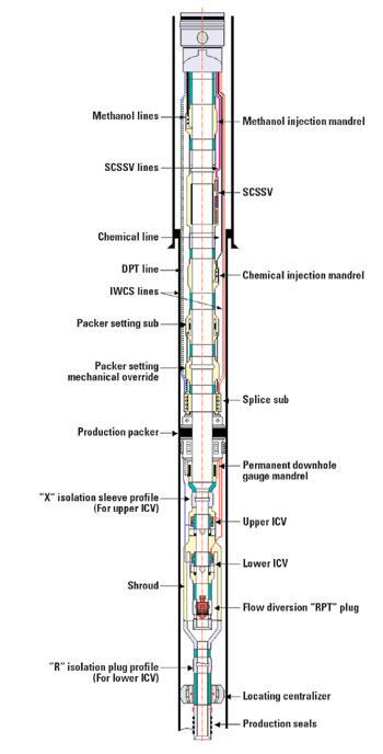
Wellbore cleanout. All completions commenced with a stringent wellbore clean-out program. The suspension cement plugs were drilled out and suspension mud displaced using the latest cleanup system technology. Casing brushes and 360° scrapers were used to mechanically clean the casing. Screen-type junk baskets and string magnets run in conjunction with these devices collected additional debris. Surfactant pills were used to remove mud deposits. The riser was scraped with a riser brush, and the BOP cavities were cleaned out with dedicated jetting tools. Once clean, the wellbores were displaced with seawater and then to 10.5 – 10.7 ppg CaCl2 brine (300 – 700 psi overbalance), filtered to 20 nephelometric turbidity units (NTU) or less. Perforating. Following cleanup, an ultrasonic cement bond log with a gamma ray tie-in log and collar locator was run on the MC305 wells. The bond log was omitted on MC348 wells due to operator preference. The sump packer, set on electric line below the lowermost perforation, was correlated to openhole log depths to serve as the depth reference for all subsequent operations. Intervals in all wells were perforated overbalanced using tubing conveyed perforating (TCP) guns. A simple perforating BHA was used, consisting essentially of: a locating snap-latch, the guns themselves, a fill-disk, and a hydraulic firing head (with drop-bar backup). The wells were not flowed after perforating. This method proved to be simple, reliable, and relatively low-risk compared to underbalanced perforating in unconsolidated sands. Perforating operations went smoothly in all wells except the first, MC348 1. In this completion, the TCP guns split after perforating the upper interval. Two days of cleanout operations were required to recover debris from the top of the packer plug before running the gravel pack screens. No cleanout trips were required after perforating any other zone. Sand control. After perforating, the lower zone frac-pack assembly (including the formation isolation valve discussed below) was run. Screens typically used in the MC305 wells were specific single-wire wrap with shunt tubes to ensure adequate treatment of the long intervals, optimize flowrates, and minimize skin effects. Screens used on the MC348 wells were pre-packed with resin-coated 20/40 proppant. The sand control treatments were pumped from a stimulation vessel. Although this vessel has the capability to be operated in a DP mode alongside Spirit, it was moored alongside the drilling rig using inflatable marine bumpers. On the MC305 wells, a data frac to optimize and validate the frac design was performed before the main treatment. During pumping operations, BHP was monitored real-time via a live annulus. Data fracs and live annuli monitoring were omitted from the MC348 frac programs due to operator preference. Following the lower zone sand control operation, a plug was set in the lower frac-pack packer. A sand or calcium carbonate pill was then spotted on top of the plug to facilitate eventual washing of perforating debris prior to plug retrieval. The upper zone was then perforated in the same manner as the lower, and the packer plug was retrieved. The upper zone sand control equipment – which was similar to the lower but included a multi-zone seal assembly polished-bore receptacle (PBR) run near its base – was then run, and the upper zone was frac-packed. Zonal isolation and fluid loss control. To secure the well from completion fluid losses and gas influx from the formation following the frac-pack operations, an isolation valve was run below each frac-pack packer housing assembly. This valve allowed all integrity pressure testing to be performed and the well to be subsequently opened for flow with no wireline or coiled tubing intervention (other than contingency operations). Following each frac-pack operation, a shifting tool located on the bottom of the washpipe was pulled through the screens as the frac service tool was retrieved. This tool shifted a sleeve, which in turn closed a ball-type isolation valve, isolating the completed interval from fluid loss and influx. The upper frac-pack assembly was stabbed into the lower packer bore, with seals straddling the lower frac-pack circulating ports. The isolation valve run on the lower frac-pack assembly included a nitrogen spring chamber, giving it the ability to be opened hydraulically by applying a series of pressure cycles down the production tubing string. In this way, the lower interval could be opened to flow without intervention after the upper completion was in place. A through-tubing shifting tool that could be run on wireline or coiled tubing through several 2.562-in. restrictions in the upper completion was available as a contingency. As a further contingency, the ball was designed to be milled on coiled tubing. Since the upper isolation valve was mechanically shifted open when the isolation assembly was installed, no nitrogen spring was required on this valve. After the upper zone frac-pack operations were complete, an isolation assembly was installed. This assembly comprised, from top to bottom: isolation packer; 35-ft long production seal bore; annular formation isolation valve; locating centralizer; isolation tubing with carbide blast rings; isolation seal assembly; and formation isolation valve shifting tool. The isolation seals were stung into the multi-zone PBR to isolate the upper zone from the lower and provide an annular flow path into the upper completion. The shifting tool mechanically shifted open the upper zone isolation valve as it was run, allowing losses to the upper zone (at rates up to 8 bpm) until the isolation packer was set. The system was designed to allow washing of debris from the top of the upper isolation valve without inadvertently setting the packer. This washing contingency was never required, as no significant debris was encountered. The annular formation isolation valve was similar in specs and concept to valves run in the sand control assemblies, providing fluid isolation from both above and below. The primary difference was that the annular isolation valve contained a sliding sleeve instead of a ball valve. The closing mechanism, consisting of a shifting sleeve and a nitrogen spring, was essentially the same as the hydraulic/mechanical formation isolation valve. The annular valve was opened hydraulically by applying a series of pressure cycles down the production tubing string after the upper completion was in place. Through-tubing contingency options were also available, and the valve had to be opened using the wireline shifting tool on MC305 3 after it failed to open hydraulically. Workstring failure. The 4-1/2-in. OD, 15.5 ppf, S-135 tubing with premium two-step connections that was used as a workstring failed during completion of the second well, MC305 2. This tubing, purchased new for this completion program, parted at the base of a pin about 3,000 ft from the top of the string while attempting to shift the service tool following lower zone pumping operations. Since light fluid was present in the tubing at this time, the well began to flow. The shear rams were closed to secure the well. The string parted a second time while it was being fished in the riser. Both failures occurred at tensile loads significantly less than rated pipe capacity. The cause of the pipe failure is still uncertain. Initial analysis indicated that the failure mechanism was hydrogen embrittlement, although no source of hydrogen has ever been positively identified. Tests conducted on the workstring indicate hardness values and yield strengths within the prescribed limits for this pipe, albeit near the high end of the acceptable range. The workstring was replaced with a P-110 grade rental string, which was also suitable for the remaining planned operations. The parting of the workstring led to extensive coiled tubing operations to clean out and recover pipe left in the well. Recovery of formation sand inside the workstring indicated that the proppant pumped into the screen/casing annulus had back-flowed through the service tool, resulting in a loss of sand-control integrity. The frac-pack service tool was successfully recovered, but efforts to recover the frac-pack packer failed. Fishing operations were then aborted, and the well was subsequently abandoned and sidetracked. The completion of the sidetracked wellbore proceeded without incident. UPPER COMPLETION The upper completion consisted of the following accessories run on the production tubing, from top to bottom: tubing hanger; chemical injection mandrel (methanol); surface-controlled subsurface safety valve (SCSSV); chemical injection mandrel (scale inhibitor); intelligent well completion system (IWCS); and production seal assembly. Hydraulic and electrical control lines were run to provide power and communication to the various devices. Cross-coupling protectors were installed on each tubing joint, and specialty clamps were run above and below the injection mandrels and the SCSSV. The formation isolation devices in the lower completion provided a secure, static wellbore while the upper completion was run. A simplified upper completion schematic is shown in Fig. 4. Again, detailed lessons learned and recommendations for the upper completion are in the original paper.1
Intelligent well completion system. The IWCS equipment comprised a packer-setting sub, a retrievable production packer, a mandrel containing three sensors, and two control-line-actuated interval control valves (ICVs). The equipment was designed to allow either producing interval to be shut in independently in the event of water encroachment during the production life.8 The ICVs were hydraulically actuated through the subsea control system via the subsea control module (SCM) on the tree. The ICV is a hydraulically actuated sliding sleeve with a tungsten carbide metal-to-metal seal. Each ICV contains a locking-close mechanism, which prevents unwanted actuation and provides a “fail as-is” feature. Two valves were used in tandem to allow independent production from the intervals of interest; zones can be produced commingled or independently, as desired. A flow shroud around the lower valve diverted production from the upper interval, in through the upper ICV. The ICVs can be shifted mechanically with a wireline – or coiled tubing – conveyed tool in the event of a hydraulic failure. An enhancement to IWCS equipment over that run in previous completions was addition of a means for mechanical, i.e., wireline, isolation of a leaking ICV seal as a contingency. The isolation tool would locate in an X-nipple placed below the gauge mandrel, straddling the upper ICV and sealing in a polished bore below it. The lower zone could then be produced through the tool ID. If the lower ICV fails to close or seal, an R-plug can be run below the shroud to allow isolation of the lower zone. The production packer was a control-line-set, hydraulic, retrievable type, with bypass for five, 1/4-in.-OD control lines. The packer was set using a packer-setting sub that worked on an internal ratcheting mechanism. This packer-setting sub, a design never run prior to this project, enabled the tubing string to be pressure tested at various points of the operation to confirm system integrity. After a designated number of cycles, the packer would set without need for wireline intervention. A wireline back-up method was installed to allow a manual method to set the packer if the packer-setting sub failed to operate. The IWCS assembly included permanent downhole gauges (PDGs) containing three pressure/temperature sensors. Data from the upper, lower and commingled flowstreams is measured. The sensors are located upstream of the ICVs, so pressure build-up data can be gathered from a shut-in interval while the other interval is flowing. Near the end of the completion of MC305 4, a leak from below the production packer into the common-close hydraulic control line was detected. The source of the leak, which is still not positively identified, is either a damaged control line or control-line fitting, or a leak past the seal stack in the piston chamber of the ICV. The well is currently producing with an ROV-operated valve closed on the tree, isolating the common-close line from the Subsea control module (SCM). Chemical injection. Chemical injection mandrels were run just above the production packer and just above the SCSSV. The lower injection point is for eventual injection of scale inhibitor, and the upper injection point is for methanol used for hydrate mitigation. Each mandrel contained a single injection valve, comprising a dual-check arrangement and a shear piston. Two separate injection lines (run to maximize methanol injection rates) joined in a special Y-block manifold above the upper valve. The shear piston allowed internal pressure testing of the injection line fitting after it was made up to the valve. Subsurface safety valve. The SCSSV selected for these wells was a field-proven, deep-set design. Closing force for the flapper is provided by a nitrogen chamber, which has a precharge based on expected well conditions. The valve had dual, independent operating systems for redundancy, including control line filters, nitrogen chambers, and operating pistons. The valve is not self-equalizing; it is equalized before opening by pressuring with methanol above the flapper. The valves were set deep enough so static wellbore temperature exceeds the maximum hydrate formation temperature at valve depth (about 2,300 to 2,600 ft below mudline). The valve in MC348 2 was set at 9,894 ft RKB, making it the deepest SCSSV ever set. The valve design has performed well, with no leaks noted even after several inadvertent flapper closures at rates up to 40 MMcfd. Control lines and tubing running. Nine control lines were necessary to provide hydraulic power, electrical power and communication, and chemicals to the downhole equipment. All control lines were made from Alloy 825. The hydraulic connectors chosen provided a redundant metal-to-metal seal that could be tested externally to ensure integrity. The lines were encapsulated together in three flat-packs. This configuration required project-specific cross-coupling protectors and specialty clamps for the chemical injection mandrels and the SCSSV.1 Production tubing (4-1/2-in.-OD, 15.5 ppf, Range 3 13Cr95 with a premium two-step upset connection) was racked back offline in 3-joint stands for faster running. The tubing joints were manufactured to a controlled length (+/-0.01 ft) to facilitate spaceout calculations. A unique false rotary system was used for running the production tubing with the multiple control lines. This system incorporated a raised platform where the tubing slips and tongs were located. The control lines passed over hydraulically operated gooseneck rollers below the slips, where they were clamped across the tubing connection that had just been made. Since the flat-packs did not have to pass through the slips, there was no chance of damaging the control lines when running. The centralizer sheared with 10,000 lb set-down weight as the completion was lowered into its final position. As a result of meticulous attention to the tally, the controlled length of the tubing joints, and the locating centralizer, no spaceout problems were encountered on any well. The tubing hanger interface accommodated all nine penetrations through use of the same proprietary hydraulic connectors used downhole and an industry-proven, dry-mate electrical connector. After apermanent downhole gauge (PDG) in the first completion, procedures were modified to include a full test of the electrical connector and PDG system through the subsea control system after the tubing hanger connection was made. A simplified schematic of the tubing hanger functions is included in the original paper.1 Significant interface work was required between the subsea control system supplier and the IWCS supplier. Development of a subsea gauge interface (SSGI) card was required by the IWCS provider to allow power and communication from the subsea control system to the downhole equipment. This technology was not new to the industry, though it was a first-article build for the IWCS supplier for this specific subsea control system company. To ensure that the subsea hydraulic system was sufficient to control the IWCS equipment, additional interfacing was required. WELL FLOWBACK AND SUSPENSION After the production packer was set and the isolation valves were opened, the well was flowed to temporary facilities on the rig for cleanup and evaluation and to verify mechanical integrity of the completion. The ICVs, controlled via the IWOCS, were used to selectively isolate and flow individual completion intervals within each well. Downhole pressure and temperature data was monitored at surface throughout the flowing and subsequent shut-in periods. See the original paper for specific lessons learned and recommendations for the flowback/suspension phase.1 Subsea completion tree. A subsea completion tree (SCT), which acted as the interface between the landing string and the hydraulically operated tubing hanger running tool (THRT), was used to provide well shut-in and disconnect capability during well flowback operations, as detailed in the original paper.1 Hydraulic and electric supply were conveyed via a 1.5-in.-OD umbilical clamped to the landing string. The electro-hydraulically controlled SCT was capable of shutting in the well and disconnecting in 15 sec. Full control of the SCT, the THRT, and certain downhole completion functions (ICVs and SCSSV) were maintained from the time the SCT was made up to the tubing hanger until the tubing hanger was landed. At that time, control of the downhole functions was transferred to the IWOCS via the tree’s SCM. For this project, a special junk basket was fabricated and run in the landing string above the accumulator module. This junk basket was designed to catch any debris present in the riser before it could fall into the subsea tree and potentially interfere with landing the tubing hanger. The SCT assembly was made up and tested offline in the aft rotary, saving up to 24 hr of rig time per well. Flowback operations. Prior to setting the production packer, CaCl2 completion brine containing corrosion inhibitor, bactericide, and an oxygen scavenger was circulated into the production tubing/casing annulus. This inhibited fluid was displaced down the tubing with a 50/50 glycol/drillwater mixture. The mixture not only provided a light column in the production tubing to eventually allow the well to flow, it also provided hydrate inhibition during the early stages of the flowback. Among modifications made to the rig was installation of permanent piping from the rig floor to the well test facility area and from there to the base of the flare boom. A flexible, high-pressure hose connected the surface flowhead to this hard-piped flowline. Spirit has no permanently installed separation facilities or flare boom, so temporary equipment was set up on the rig during the first completion. It remained there throughout the program to eliminate need for repeated hook-up, testing, and commissioning. Gas at rates up to 30 MMcfd and the minor amounts of condensate produced during the flowback were flared. The wells were brought online using a controlled ramp-up, with rates stabilized at predetermined levels (usually 10, 20 and 30 MMcfd) for evaluation. Maximum drawdown limit was set at 300 psi as measured on the downhole gauges. Surface gas and condensate samples were taken throughout the flow periods. The lower interval was shut in with the downhole flow control valve, and pressure build-up data was gathered while the upper interval was flowed. Safety and environmental. Producing a high-rate well to a DP vessel raises a number of safety and environmental issues. Perhaps chief among these is loss of well control if a vessel drive-off should occur. The SCT and surface well test equipment provider worked with the WIPT and the drilling contractor to coordinate existing emergency shut down (ESD) actions. Four station-keeping status regions were established.1 Required contingency actions by drilling crew and SCT provider personnel were clearly identified for each completion operation, and these actions were reviewed regularly with the affected personnel. A series of simple illustrations summarizing the required action were kept for immediate reference at the driller’s station on the rig floor at all times. ESD stations, from which the well could be shut-in remotely if the need arose, were located at key locations throughout the rig, and near lifeboat muster stations. Large volumes of methanol were required to prevent hydrate formation during the flowback; and safe handling of the methanol on the rig was a primary concern. Twelve 2,000-gal methanol tanks were aligned on the riser storage deck for each flowback. A deluge system was installed across the framing of the tanks, and a full-time fire watch was assigned. Well suspension. Following the flowback operation, the SCSSV flapper was closed, and the production tubing above the SCSSV was filled with methanol via the IWOCS umbilical. The tubing hanger isolation sleeve was pulled with slickline, and gas pressure was bled from the landing string through the production facilities. The landing string was then filled with completion brine by circulating down the kill line and through the tree’s annulus access valve. The tubing hanger crown plug (THCP) was then installed on slickline. The CT lift frame and surface flowhead were laid down, and the landing string and SCT were pulled. The internal tree cap (ITC) was run on the workstring using a mechanical running tool (MRT). After landing the ITC, select BOP pipe rams were closed around ported function joints on the ITC MRT. The ITC was set by energizing hydraulic access ports on the MRT by pressuring the appropriate choke or kill line. The MRT was released by rotating the workstring. The ITC MRT failed on the MC348 2 completion – a design deficiency that allowed a piston inside the tool to become hydraulically locked under certain conditions. This problem was handled by contingency systems; it was rectified for subsequent completions.1 CONCLUSIONS Challenges faced in completing the Aconcagua and Camden Hills wells in record-setting water depths were successfully met and overcome. Some specific conclusions, lessons learned, and recommendations are offered in the above discussions. High-level conclusions are presented here.
Further, contingency plans are of equal importance with primary plans. They must be fully thought out, tested and available to implement on the rig. And, finally, project success depends on attention to detail on all equipment and procedures, not just the “high-tech” aspects.
|
||||||||||||||||||||||||||||||||||||||||||||||||||||||||||||||||||||||||||||||||||||||||||||||||||||||||||||||||||||||||||||||||||||||||||||||||||||||


- Prices and governmental policies combine to stymie Canadian upstream growth (February 2024)
- U.S. producing gas wells increase despite low prices (February 2024)
- U.S. drilling: More of the same expected (February 2024)
- U.S. oil and natural gas production hits record highs (February 2024)
- X80 heavy wall pipe solutions for deep/ultra-deepwater field developments in mild sour environment (November 2023)
- Wellbore seal control and monitoring enhance deepwater MPD operations (October 2023)

