Engineered high-pressure coiled tubing cleanouts
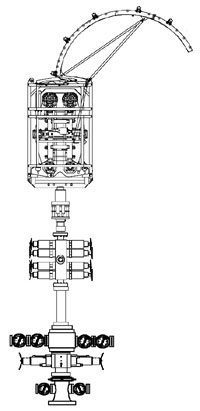
Well Control & InterventionEngineered high-pressure coiled tubing cleanoutsDesign basics and example application of coiled tubing intervention to clean-out a 17,000-ft well with 16,000-psi BHP and 380° F temperatureStephen Rowland, BJ COILTECH, Ralph Hamrick, Dominion Explorations & Production Inc. and Greg Gero, Baker Hughes INTEQ Described in this article are important inputs to job design engineering for a high-pressure, coiled-tubing sand cleanout in a deep South Texas well. Circulation, force and stress analysis design criteria, and fluid selection are discussed, plus determination of fatigue analysis – the final step in job planning. Beginning in April 2002, the well was successfully cleaned out and a cast-iron bridge plug was installed to abandon a bottom- water zone. INTRODUCTION The petroleum industry has always been challenged with the requirement to "push the envelope" and enter into new and challenging frontiers. One area of growth in the E&P side of the business has been the exploitation of high pressure/high temperature formations. Drilling and completing these wells has required dealing with a number of issues concerning safety and operational performance. Similarly, workover operations have to properly address these extreme conditions. Dominion Exploration & Production recently drilled an "S"-shaped well to a total depth of 17,800-ft MD (17,715-ft TVD). The well was completed to TD with 4.5-in x 3.5-in. chrome production tubing cemented in place and perforated at the lower wilcox. Testing of this interval determined it produced excessive amounts of water and led to the production of formation fines which eventually filled the lower section of the wellbore. A coiled tubing cleanout was determined to be the best method to remove the sand bridge. This would allow setting of a cast-iron bridge plug at 16,800 ft to isolate and abandon the zone. Fundamental areas of concern for this operation included high bottomhole pressure (BHP), high bottomhole temperature (BHT), presence of H2S and CO2, and difficulties cleaning sand out of an “S” shaped wellbore. Proper engineering design and planning are key to performing this type of operation safely and successfully. JOB DESIGN Engineering of a high-pressure, coiled-tubing cleanout requires detailed assessment of expected and worst-case treating parameters. A complete design ensures that the job can be executed safely under any conditions the well may present. A high-pressure gas well can expose the CT to high stress if well control is lost and gas is allowed to displace fluid on the back side, creating higher wellhead pressures. Under this condition, the CT is exposed to higher axial stresses due to the loss of buoyancy and higher hoop/radial stresses due to pressure differential. These higher potential stresses need to be examined to ensure that the CT can endure, and be safely retrieved. Additionally, all surface equipment has to be able to operate at the elevated pressure to maintain a safe working environment. Failure to examine the worst-case scenario can lead to serious job problems, including CT failure and total well-control loss. Although it is critical to account for the maximum wellhead pressure, most high-pressure CT cleanout jobs are designed to operate at lower wellhead pressures by circulating a weighted fluid and maintaining a constant BHP with the choke. In a gas well, BHP is held constant at, or slightly above, reservoir pressure. Any gas migration into the well will cause a reduction in hydrostatic head, inviting additional gas to enter the wellbore. If gas is allowed to penetrate into the wellbore, time will be consumed regaining well control and equilibrium; and it could lead to the worst-case scenario. For this reason, a thorough hydraulic analysis needs to be performed to produce a reliable choke schedule. In a cleanout, the hydraulic analysis has to account for equivalent circulating densities due to the entrainment of solids, fluid friction on the backside and fluid properties. Ignoring these parameters can lead to excessive fluid loss during treatment, resulting in a decrease in hydrostatic head and gas infringement. It is, therefore, critical to perform the analysis to ensure that well control is maintained, solids are removed, and to define expected operating pressure for the CT and auxiliary equipment. For the case well, a BHP of 16,353 psi (18.3 ppg equivalent) was assumed, based on pressures encountered during drilling. Using this assumption and accounting for the hydrostatic effect of a column of gas, the maximum possible surface pressure was 14,400 psi. While the available CT, Table 1, and equipment is capable of safely handling this pressure, it was not advisable to perform the cleanout under these conditions due to accelerated CT fatigue. It was, therefore, important to engineer a fluid that would reduce wellhead pressure while maintaining minimum surface treating pressures. Design requirements of the fluid also included the ability to preserve carrying capabilities at a BHT of 384°F, withstand shear through the motor assembly and control H2S. The final fluid design played a crucial role in determining expected pressures, flowrates, motor efficiency and rate of penetration. A 13.9-ppg CaBr (13.53-ppg bottomhole equivalent) was chosen for the operation. Several additives were incorporated into the fluid including: a specialized polymer to increase carrying capacity, a friction reducer to minimize injection pressure, and an H2S scavenger to protect CT and surface equipment. CIRCULATION/FORCE/STRESS ANALYSIS Final design of fluid properties allowed all variables and well parameters to be used as input for a proprietary, computer program that models expected operating pressures and associated forces applied to the CT. The final design was determined by optimizing fluid rate, motor performance and rate of penetration, while remaining within the operating envelope of all equipment. All surface equipment on location and the wellhead had a 15,000-psi operating pressure, which governed maximum operating limits, Fig. 1.
Based on design criteria for annular velocity, motor performance and circulating pressures, the optimum design was engineered to circulate fluid at 1.25-bpm rate and penetrate the fill at a rate of 12 ft/min. The top of the fill was expected to be encountered at about 14,752 ft and, at this depth, calculated surface circulating pressure was 11,100 psi. To maintain the constant BHP, back pressure applied by the choke was calculated to be 6,400 psi. As the fill is penetrated, hydrostatic head will increase due to solids entrainment and the fact that weighted fluid is being placed deeper in the well. It is, therefore, necessary to generate a choke schedule to ensure constant BHP, Table 2.
Fatigue analysis. A final step in job planning is determination of fatigue conditions and usable CT life. In operation, the CT is in a state of plastic deformation on the reel and across the gooseneck. Plastic deformation and cycling of the CT results in fatigue, which reduces its operational life. At elevated pressure, fatigue is accumulated at a much higher rate. It is, therefore, necessary to ensure that the available CT string will be capable of completing all tasks, as outlined in the job scope, prior to consumption of the useful life, Fig. 2.
Job history. Work began on the case well on April 29, 2002. The job required slight design modifications on location to correspond with actual well conditions but, for the most part, corresponded to predicted values, Fig. 3. The well was successfully cleaned and the cast-iron bridge plug was installed.
|
||||||||||||||||||||||||||||||||||||||||||||||||||||||||||||||||||||||||||||


- Coiled tubing drilling’s role in the energy transition (March 2024)
- Shale technology: Bayesian variable pressure decline-curve analysis for shale gas wells (March 2024)
- Using data to create new completion efficiencies (February 2024)
- Digital tool kit enhances real-time decision-making to improve drilling efficiency and performance (February 2024)
- E&P outside the U.S. maintains a disciplined pace (February 2024)
- Prices and governmental policies combine to stymie Canadian upstream growth (February 2024)
- Applying ultra-deep LWD resistivity technology successfully in a SAGD operation (May 2019)
- Adoption of wireless intelligent completions advances (May 2019)
- Majors double down as takeaway crunch eases (April 2019)
- What’s new in well logging and formation evaluation (April 2019)
- Qualification of a 20,000-psi subsea BOP: A collaborative approach (February 2019)
- ConocoPhillips’ Greg Leveille sees rapid trajectory of technical advancement continuing (February 2019)

