Sand Control
Remedial sand control options, a closer look at Vent Screen Gravel Packing techniques
Use of coiled tubing with recently revived dual screen gravel packing techniques is replacing rotary rigs on many remedial well operations
Robert A. (Robbie) Picou, Engineering and Product Manager, Thru Tubing Systems, Metarie, Louisiana
Over the past 15 years, the author has been directly involved in design, development and exploitation of several techniques linked to thru-tubing/remedial sand control. During this time, several new, and many revived but older, systems have been developed and successfully employed for the purpose of rig-less installed gravel packing systems. Remedial sand control is one of the fastest growing technologies involving thru-tubing well remediations utilizing coiled tubing and/ or wireline deployment systems. The purpose of this article is to take a closer look at an older, but recently revived remedial gravel packing technique, “the Vent Screen or Dual-Screen Gravel Packing method.”
THRU-TUBING GRAVEL PACKS
Although there are four separate techniques of thru-tubing gravel packs examined in this study, only the vent-screen technique will be discussed here. This is due to article length constraints, as well as the Vent-Screen Gravel Pack (VSGP) method’s popularity and mystique. The other systems studied are: 1) One Trip Squeeze; 2) Vent Screen; 3) One Trip Circulation; and 4) One Trip Wash Down.
VENT SCREEN GRAVEL PACK (VSGP) SYSTEM
The Vent Screen technique uses two screen assemblies separated by blank tubing. The assembly is placed in the well with the lower screen assembly spaced out across the productive interval. A selected length of blank pipe connects the lower screen to the upper “vent screen.” Gravel is packed around the lower screen assembly, and all or a portion of the blank pipe casing annulus, as shown in Fig. 1. This system allows the well to flow into the gravel-packed screen casing annulus, into the lower screen, up the blank pipe and exit out of the upper or “vent screen” attached to the top of the blank pipe. Integrity of the gravel pack is maintained by the packed gravel-pack proppant filling the blank-pipe casing annulus.
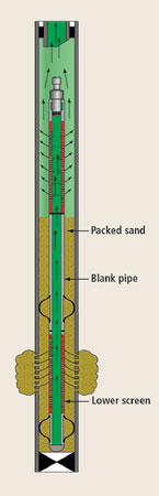 |
Fig. 1. Typical vent screen after gravel packing.
|
|
As long as the packed proppant in the blank-pipe casing annulus (BPCA) is sufficiently long to divert flow inside the lower screen, up the blank pipe and out of the vent screen without fluidizing the same, the gravel pack maintains its integrity. However, if the pressure differential (DP) created by flow through the vent screen assembly exceeds the pressure at which the packed proppant in the BPCA will fluidize, then the gravel pack will fail. As this occurs, the proppant in the blank and lower screen annulus fluidizes, creating a flow path of least resistance up the vent screen assembly annulus rather than through the vent screen assembly inside diameter.
Noteworthy features. This system also has many other features that have been responsible for its recent utilization. Listed below are some of the most noteworthy features and benefits:
- The Vent Screen assembly does not need to be tied back to the production tubing. This allows for ease of future plug-back completions uphole.
- The assembly can be deployed on coiled tubing, electric wireline or slick wireline. Multiple deployment vehicles create flexibility and cost savings.
- The system is compatible with multiple proppant-placement techniques, such as frac packs, extension packs, or high-rate, water-pack slurry placement techniques. The slurry can be displaced via production tubing, coiled tubing or other suitable concentric workstrings. In many applications, the proppant can also be conveyed via wireline dump bailing around the assembly. However, this technique exhibits many limitations.
System limitations, failure causes. Although the Vent Screen technique has many noteworthy features and potential benefits, the system also contains one major “Achilles heel.” As described above, the VSGP assembly has no mechanical sealing device isolating the gravel-packed screen annulus from flow above the pack further preventing fluidization and eventual failure of the pack, as with most other remedial and primary means of gravel packing. This Achilles heel has also been responsible for the VSGP system having the highest failure rate of the systems mentioned in this study.
Several techniques have been used to minimize this concern, with varied success. One company has developed software designed to predict the length of packed blank pipe required for a given set of flow parameters to prevent gravel-pack fluidization. Other systems have included utilization of curable, resin-coated proppants, electro-chemical bonding proppant slurry additives and dump-bailed cement or resin on the top of the packed proppant inside the BPCA.
The VSGP system has been used successfully in more than 100 applications in Gulf of Mexico oil/gas fields in the last year. The failure rate can be attributed to several causes, the principal one, this author believes, is “not fully understanding the failure dynamics involved.” The discussion below will attempt to uncover some of these vent screen dynamics.
Assume we can calculate the optimum packed length of blank pipe annulus required to prevent the gravel pack from fluidizing. Also assume we have investigated the maximum DP to be exerted for flow through the vent screen assembly, taking into account what the well will produce initially, and through zone depletion. This is necessary because DP across the vent screen assembly may change due to different mixes of produced fluids and/ or bottomhole pressure experienced during well life. A good example is a high-pressure gas well producing at a given production rate and a corresponding DP through the vent-screen assembly. As BHP declines and rate is maintained, DP across the vent screen assembly increases as a function of gas compressibility.
Assume we have addressed all possible effects of DP created by flow through the vent assembly, and the corresponding length of packed blank casing annulus is known. The next challenge is accomplishing this goal during gravel pack application. To expose the potential problems that exist, the following scenarios are discussed.
| |
The proposed Vent Screen BHA consists of, from top down |
|
| |
Item |
Description |
ID, in. |
OD, in. |
Length, ft |
|
|
|
|
| |
a |
Vent screen 6-ft long w/plug on top (0.008 gauge) and bow spring centralizers top and bottom |
1.375 |
2.10 |
12.00 |
|
| |
b |
1-1/2-in. blank pipe |
1.610 |
1.90 |
60.00 |
|
| |
c |
Production screen (0.008 gauge equiv.) w/ bow spring centralizer on top, bottom and middle w/ bull plug on bottom |
1.375 |
2.10 |
40.00 |
|
| |
|
Total BHA length, ft |
|
112.00 |
|
|
EXAMPLE 1: VSGP WITH HIGH-RATE WATER PACK, EXTENSION PACK, OR FRAC PACK PROPPANT PLACEMENT
Well data: Depth ±10,000 ft, production tubing 2-7/8 in., casing 7 in., perforated interval length 20 ft wellbore deviation 25°. Because of future uphole plug back completion, the blank-pipe length must be limited to 60 ft, to allow for P&A of current zone and uphole re-completion. Pre-job analysis determined need for a minimum of 30 ft of packed sand in the BPCA to prevent pack fluidization.
Slurry data 1: High-Rate Water Pack (HRWP), 5 to 10 bpm displacement rate, proppant loading, 1 to 4 ppg of carrier fluid.
Slurry data 2: Extension Pack, 10 to 15 bpm displacement rate, proppant loading – ramped from 1 to 4 ppg, carrier fluid 35-lb linear gel.
Slurry data 3: Frac Pack, 10 to 20 bpm displacement rate, proppant loading – ramped from 1 to 15 ppg, carrier fluid cross linked polymer of suitable surfactant type. The proposed Vent Screen composition is listed in the accompanying table.
Once the above vent screen BHA is landed in the well, the slurry pumping operation can begin. In the first two slurry-example HRWP and Extension Pack techniques, the following characteristics exist: medium to high-rate slurry displacement and low to medium proppant loading. As the slurry displacement commences, the following sequence of events occurs:
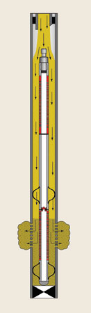
- Slurry enters and travels down the production tubing, the well casing, down around the vent screen BHA and into the productive interval via the production perforations, Fig. 2.
- Proppant dehydrates against the formation face and continues to dehydrate from the carrier fluid back into the wellbore opposite the lower or production screen of the Vent Screen BHA. Once the lower screen casing annulus is packed with dehydrated proppant, the flow regime changes dramatically, Fig. 3.
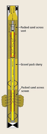
- At this instant, the flow regime changes from traveling down around the outside or annulus of the vent screen BHA to entering into the vent or upper screen of the assembly. Proppant begins to dehydrate across the vent or upper screen as carrier fluid travels inside and down the vent screen, blank pipe, and lower screen inside diameters. The carrier fluid then exits the lower screen and enters the gravel-packed annulus adjacent to the lower screen, then eventually into the productive zone through the production perforations.
- As this occurs, the vent or upper screen casing annulus packs off with dehydrated proppant, causing a “sand out” and corresponding pressure increase at the surface. This pressure increase eventually ends the gravel pack pumping operation and is commonly referred to as a sand out or screen out, Fig. 4. In these two examples, the above screen-out scenario occurs in the same manner. At a slurry displacement rate of 10 bpm and in the wellbore geometries discussed in this example, screen out of the upper vent screen occurs in ±16 sec, once the main screen annulus has been packed or sanded out.
 |
 |
 |
Fig. 2. With vent screen assembly in place, sand packing can begin.
|
|
Fig. 4. Packed sand across vent sands out causing distinctive pressure increase, to define end of gravel packing procedure.
|
|
Fig. 3. Carrier fluid from sand pack slurry flows through vent downward and into the production zone as the annulus sand pack forms.
|
|
The above scenario is typical for most common VSGP assemblies, no matter whether the slurry pumping is an HRWP, an Extension Pack, or a Frac Pack. The major problem with this scenario is the effect it has on the goal of packing at least 30 ft of blank annulus, as required in this example. Most observed procedures recommend re-stressing the pack and eventually washing out the remaining proppant above and/or around the vent or upper screen and returning the well to production. Other procedures may recommend putting the well on production immediately following the screen out and attempting to produce back the excess proppant located above and around the vent screen.
DETAILED REVIEW OF THREE SCENARIOS
Remember that a minimum of 30 ft of packed sand in the blank pipe annulus is required in this example to prevent pack fluidization and eventual failure. The following is a close examination of all three pumping scenarios and their effect on this requirement.
HRWP. In this pumping scenario, at the time of the screen out, proppant loading in the carrier fluid was 1 ppg. As discussed above, the vent screen sanded out ±16 sec. after the lower screen casing annulus packed off. At this point, the following conditions exist at and around the VSGP assembly, Fig. 4. Proppant is packed in the lower screen casing annulus as well as the upper or “vent” screen annulus. However, at the point where the pumping operation ended, the blank pipe annulus contained “slurry” of carrier fluid with a 1 ppg proppant loading.
If enough time was given for the proppant to settle out of the carrier fluid and form a sand pack in the blank casing annulus, pack height would only be about 10% of slurry height in the blank pipe. This would equate to roughly 6 ft of packed sand in the BPCA. If additional efforts were not made to increase packed-sand height of the BPCA, failure of the pack is probable.
Extension Pack. In this scenario, the main differences in slurry composition and pumping operation are: a 4-ppg slurry proppant concentration, a linear-gel carrier fluid and a slurry pump rate of 10 to 15 bpm. The same sequence of events occur as discussed in HRWP, except they occur at a faster pace due to higher proppant loading and increased slurry displacement rates. In this case, at the end of the pumping operation, a slurry consisting of a linear gel carrier fluid with a 4-ppg proppant concentration occupies the BPCA, while proppant is again packed across the lower production screen and upper vent screen annuli.
If sufficient time is allowed for the slurry to settle, and assuming the well is near vertical at the point where the vent screen is landed, net packed-proppant height would equate to ±25% of total blank-pipe length. In this case, proppant height would be ±15 ft. Still, this is only half the height required in this example, creating yet another failure probability.
Frac Pack. In this scenario, the main difference is that a ramped frac pack treatment is applied. It is assumed that the frac job was applied as planned and a tip screen out occurred when the higher proppant concentration was at the vent screen assembly, i.e. 12 to 15-ppg proppant loading, and the same conditions exist. In this case, the BPCA is occupied by slurry consisting of normally a cross-linked frac fluid with a proppant loading of 12 to 15 ppg. If the proppant in the BPCA were allowed to settle out, then the packed sand height would be ±60 to 75% of the total blank-pipe length. This could create a height of ± 45 ft in the blank-pipe annulus, which would satisfy job goals of a minimum 30 ft of packed sand in that annulus.
Keep in mind the success of this scenario is accomplished only if the frac job sanded out as planned when the highest proppant concentration was adjacent the vent screen BHA. If the frac job sanded out prematurely, the same failure mechanism would exist as in the first two examples. The same could be true if the frac job did not sand out and was over displaced. These scenarios commonly occur.
Also, it is worth noting that frac fluids are designed to suspend proppant and control leak-off, thereby propagating the fracture. These desirable characteristics, however, may inhibit sand settling in the BPCA. It is worth evaluating the frac fluid breaker schedules for any given bottomhole temperature to ensure enough time is allowed for the proppant to settle and create a pack in the blank-pipe annulus. This may delay restoring the well to production for quite some time. Also, lab testing should be conducted to better estimate time required to establish a stable grain to grain pack, as residual polymer coating may inhibit pack efficiency.
As noted in the above examples, probability of failure exists in all of the slurry pumping scenarios if modifications are not made to the slurry placement techniques. It is also worth noting that wellbore deviation may have a severe effect on the ability to create a stable proppant pack in the BPCA. Wellbore deviations above 45° may create problems since gravity’s influence becomes less and less of an aid in creating a stable pack.
SUGGESTED SYSTEM MODIFICATIONS
The above examples point out potential failure modes for typical VSGP completions; even so, most completions observed in this study were successful. It has been learned during the past four years of study and application of these systems that a few modifications can be made that better ensure success of this remedial sand control system. The following will discuss some of these:
1. Evaluate and reduce excessive DP created by flow through the vent screen assembly. This can be accomplished by optimizing the ID or flow area of the vent screen assembly. Avoid excessive length of the assembly over what is necessary to obtain optimum packed blank-pipe annulus.
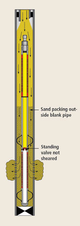
2. Addition of an expendable (shear-out) standing valve installed in the blank-pipe section of the vent screen BHA, Figs 5 and 6. The addition of a shear-out standing valve functions to plug off the downward flow path inside the vent screen assembly. This channels all of the flow during the pack placement operation to the outside or annulus of the vent screen assembly, thereby preventing the flow regime change described above until the shear mechanism of the standing valve has been sheared. Once the standing valve is sheared, it simply falls or is pumped to the bottom of the screen assembly where it has no more effect.
 |
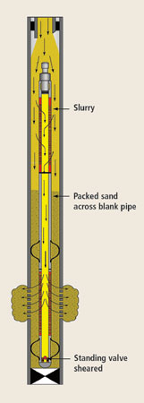 |
Fig. 5. Expendable standing valve in blank pipe prevents fluid inflow through vent, as shown in Fig. 3.
|
|
Fig. 6. At designed pressure to achieve optimum packing in annulus, standing valve shears and falls to bottom.
|
|
The standing valve, by blocking flow down the vent assembly, allows for positive pressure to be exerted on the sand pack being formed in the blank-pipe annulus. On the first example, using an HRWP technique, the standing valve can be designed to shear at a given pressure. This shear-out pressure can be adjusted to create necessary pressure required at a given slurry displacement rate to create a desired packed-sand height in the BPCA. To facilitate proper sand height and corresponding shear pressure of the standing valve, typical gravel-pack sand height calculations can be used, as well as some alterations of the pumping procedure. Normally, this entails reducing the pump rate at the end of the job once a screen out is indicated.
Once the sand out is indicated, the gravel pack is essentially complete. At this point, slurry displacement rate would be lowered, normally to a minimum 14 to 13 bpm. If shear-out pressure of the standing valve was set at 2,500 psi in the vent screen application listed above, a column of packed sand 30 ft long could be easily accomplished. Once the sand-out pressure of 2,500 psi is reached and the standing valve shears and falls to the bottom of the vent screen assembly, additional slurry can continue to be displaced at the low pump rate described above.
This low pump rate will allow additional proppant to be placed below the vent, even though the flow regime has changed to entering into the vent and exiting into the zone, as previously described. The low pump rate makes it more difficult to form a stable bridge across the vent screen, allowing gravity to be the dominant factor enabling proppant to gravitate past the vent screen and down around into the BPCA.
The shear-out standing valve or “Sand Height Control Valve” as commonly known, is best suited for HRWP proppant placement techniques; however it has a similar effect on extension pack and frac pack techniques by creating a positive pressure on the packed sand in the blank-pipe annulus, better establishing grain to grain contact in the pack.
3. Installation of mechanical isolation devices when practical. The addition of isolation devices such as thru-tubing-deployed packer systems can eliminate the concerns noted above.
CONCLUSION
Thru-tubing-deployed Vent Screen Gravel Packs have been resurrected and have become a large part of modern thru-tubing remedial sand control. Modern proppant placement techniques and better understanding of VSGP dynamics have increased the success rate of this technique.
As a result, this technology, along with other remedial gravel pack systems, have enabled operators to profitably produce reserves that were previously uneconomical using conventional gravel-pack-completion techniques. 
THE AUTHORS
|
 |
Robert A. Picou is engineering and product manager for Thru Tubing Systems, Inc., Metarie, Louisiana. He joined the company shortly after its conception in 1998. Prior to that, he was owner and president of Thru Tubing Packer Systems and president of Eclipse Packer Co. He has worked the last 10 years developing sand control and packer-related systems for thru-tubing and slimhole remedial applications. He previously worked four years for Chevron USA in drilling/ workover/completion capacity, and in various capacities for Baker Sand Control and BJ Services. He has authored SPE papers on well stimulations and thru-tubing gravel packing. Mr. Picou is a graduate of Nicholls State University.
|
| |
|
|

