Artificial Lift
What’s new in artificial lift
Part 1 – Fourteen new systems for beam, progressing-cavity, plunger-lift pumping and gas lift
James F. Lea and Herald W. Winkler, Texas Tech University, Lubbock, Texas; and Robert E. Snyder, Executive Engineering Editor
Described here are 14 recent developments in four categories of artificial lift technology, including: beam pumping (7 items); plunger lift (3); gas lift (2); and progressing-cavity pumping (PCP) (2). Part 2, coming in the May issue, will present electrical submersible pumping (ESP) and other, miscellaneous, artificial-lift-related innovations.
Beam pumping – by far the most widely used type of artificial lift – comprises a motor-driven surface system lifting sucker rods within the tubing string to operate a downhole reciprocating pump. PCP systems are based on a surface drive rotating a rod string which, in turn, drives a downhole rotor operating within an elastomeric stator. In plunger lift, a freely moving plunger falls through fluids in the tubing, or casing, and is lifted back to surface with its slug of fluid by high-pressure formation, or injected, gas. Gas-lift systems inject high-pressure gas from the casing-tubing annulus through valves into liquids in the tubing to reduce their density and move them to the surface.
BEAM PUMPING
The seven new techniques/ products for improving beam/sucker-rod pumping feature new equipment for: sucker rod connections; a traveling valve to cut gas locking; a polished rod wear sleeve seal and safety device; a novel dual displacement pump for coiled tubing; a quick portable dynamometer; a downhole fluid heater; and a unique two-stage rod pump system.
Sucker rod connection. Permian Rod Operations, Odessa, Texas, introduces a new sucker-rod connection design, which has undergone extensive lab and field testing, and finite-element analysis. The PRO/KC Connection System performed better than standard API connections by 250% in tension and torque tests. And it lasted an average of six times more cycles when fatigue tested, than API connections under the same cyclic load conditions. Shown in Fig. 1 is a cut-out comparison view of a standard API connection (top) and the PRO/KC connection.
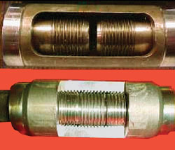 |
Fig. 1. New sucker-rod coupling/ connection (bottom) compared to standard API connection (top).
|
|
Pins and couplings are machined to a precise length and made up to a center torque button with the patented PRO/KC make-up unit. Pre-load is confirmed by measuring actual pin stretch with a dial indicator. This provides a connection with equal contact pressure on both pin shoulders, equal pre-load stretch of both pin necks, and equal contact pressure of both pin noses against the center torque button, creating a pre-load stretch at the coupling center. This effectively doubles the contact surface and friction area to carry additional loads and resist back-out. This design provides a strong, stable and solid sucker-rod connection to resist loading in tension, torsion, bending and fatigue.
Anti-gas-lock traveling valve. Kajon Oil Tools in Houston, Texas, has developed the Ballbuster, a traveling valve specifically designed to prevent gas lock. Using no ball and seat, the system opens on every downstroke, regardless of compression, and closes on every upstroke, using sliding-shear-seal technology.
The valve opens and closes by the up and down motion of the rod string, Fig. 2. On the downstroke, the valve opens by moving a carbide disc to expose a port communicating through the plunger. Fluid and gas pass up through the plunger. On the upstroke, the disc moves to cover the port, closing the valve and allowing the fluid to be pumped to surface. The hydrostatic force in the tubing acts on the disc, assuring a positive seal.
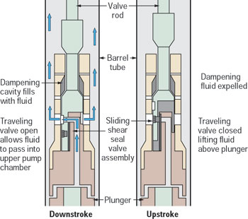 |
Fig. 2. Traveling valve system to prevent gas lock in downhole pump.
|
|
Shock is reduced as well fluid fills the dampening chamber on the downstroke and is expelled on the upstroke. Since the valve opens on every stroke, gas locking is prevented. This allows for pumping gassy wells, or from below a packer. It can also be used to pump horizontal wells.
Standard construction is forged stainless steel 17-4 PH DBH 1150 with a minimum tensile strength of 145,000 psi. Corrosion resistance meets NACE MRO175-2000. Special materials are also available. The sliding-shear seal is ground and lapped tungsten carbide. The spring, which assures that the sealing surfaces remain in contact, is elgiloy. The system mounts on top of the plunger; no plunger cage is required. The valve rod attaches to the top of the Ballbuster. A dummy cage is run on the bottom of the plunger to protect the threads.
Polished rod wear-sleeve seal. The new, patented Safety Seal Liner (SSL) from Hasco, Sapulpa, Oklahoma, supports the outer wear sleeves on polished rods (PRs) while providing a safety clamp to catch broken PRs. As shown in Fig. 3, the SSL clamps on the PR, below the main PR clamp, using set screws. The liner (sleeve) is welded onto the bottom. Packing rubbers seal off any fluid moving upward between sleeve and PR.
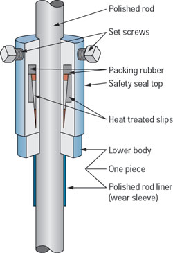 |
Fig. 3. Principal features of Safety Seal Liner system supporting polished rod wear sleeve, with rubber fluid seals and heat-treated slips to catch parted polished rod.
|
|
Should the PR break above the SSL and below the main PR clamp, the sleeve will drop through the stuffing box, the SSL will be stopped on the wellhead (stuffing box) and the PR will be caught and held by the heat-treated slips with upward-facing teeth. This action will serve to: 1) prevent excessive damage to the well and rod string if the PR breaks or slips out of its clamp; 2) help prevent an open hole and well fluid flow; and 3) save the cost of a fishing job.
Dual displacement pump system. The need to produce large volumes of fluids from secondary recovery wells, and to produce normal levels of fluid from deeper wells, prompted Coil Tubing Americas, Houston, Texas, to develop an innovative artificial lift option using a Dual Displacement Pump. Using a standard beam pumping unit, preferably with coiled tubing (CT) as the “rod string,” this patent-pending production system reciprocates the plunger of a downhole pump, and both motions of the pumping unit are utilized to convey fluid to surface. As shown in Fig. 4, while in the downstroke, production reaches surface through the ID of the CT. On the upstroke, fluids reach surface through the annular space between the CT and the production tubing.
 |
Fig. 4. Dual Displacement Pump operation using coiled tubing.
|
|
Summarizing the pumping action: On the upstroke, the: lower chamber fills; barrel standing valve opens; plunger traveling valve closes; floating traveling valve opens; annular standing valve closes; and fluid is displaced to the annular space between tubing and CT through the floating traveling valve. On the downstroke, the: upper chamber fills; barrel standing valve closes; plunger traveling valve opens; floating traveling valve closes; annular standing valve opens; and fluid is displaced through the CT from lower chamber to surface.
Pump design comprises one plunger/barrel configuration with two independent sets of traveling valves and two sets of standing valves. Full use of the pumping cycle can produce up to 80% more fluid per unit time, making the system an option to ESPs or PCPs in secondary recovery wells. While the primarily goal targeted secondary recovery wells, the system will also solve problems associated with rod strings in deeper wells. Capability of the pump to produce at least one and a half times more fluid per cycle will allow use of smaller diameter plungers for a given production rate, thus reducing rod string stresses due to fluid weight.
One important consideration is that this pump is not suitable for gas handling because one of the stages will be highly susceptible to gas locking. In early 2003, the first prototype was being tested by the developer. According to the designer, the system can lift more than 1,000 bfpd with a conventional pumping unit at slow SPM rates and standard stroke lengths. The system can be made to work with sucker rods. However using CT as the pumping string as shown, will add benefits; and further testing will prove this theory.
Self-contained quick dynamometer. Dynamometers have been used for many years to analyze beam-pumped wells. The evolution from mechanical systems to modern computerized systems has provided industry with sophisticated instruments for diagnosing wells. Typical systems require significant capital outlay and specialized training for proper use. This has limited the use of dynamometers, and it illustrates a need for a simple/accurate dynamometer-data-gathering system which is easy to set up and use.
SAM Quick Dyno, by Lufkin Automation, Houston, Texas, is a new, self-contained system that can record surface and pump cards on a well within minutes, Fig. 5. It automatically calculates inferred production based on the pump card. It also allows the operator to record valve checks and counterbalance, and perform pump leakage calculations without an on-site computer. All data can be brought to the office and transferred to a computer for further analysis, if needed.
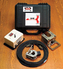 |
Fig. 5. Components of quickly installed pumping- well dynamometer.
|
|
Lufkin will release this new dynamometer system by second-quarter, 2003. This design is based on the SAM Well Manager, which is the downhole pump card rod pump controller Lufkin released last year.
Downhole heater. Lynbrook Technologies LLC, Houston, Texas, has completed design/lab testing for a downhole resistance heating system to be used to improve pump performance and production rates in heavy-oil-production applications; field testing is presently underway. Rated at 120-kW output, the system can heat up to 750 bpd of typical heavy oil from a starting point of 122°F, to as much as 203°F, significantly lowering fluid viscosity and improving performance of any artificial lift system.
In its present design, the system may be used with rod pumps or PCPs, operating in 7-in. casing. The heating element is located below the pump intake and warms fluid throughout the tubing string from below the pump to surface, Fig. 6. During design of this critical component, close attention was given to the balance between critical heat transfer elements in an oil well, including size of the heated surface area, pressure drop created by the tool, heated surface temperature and well-fluid coking temperature. System operation is fully automated, and is focused on maintaining a constant pump intake temperature based on data sent to the surface control unit from multiple pressure/temperature sensors. Historic temperature, pressure, production rate and motor loading information are stored for download/analysis.
 |
Fig. 6. Production fluid heater below downhole pump, and surface control system.
|
|
Initial analysis of well data from typical Venezuelan and Brazilian applications indicates the system should provide significant increases in daily production rates through a combined reduction of tubing losses and improved pump performance, providing the reservoir has sufficient capabilities.
Two-stage rod pump. The new 2-Stage Plus Sub-Surface Rod Pump from Performance Lift, Inc., Odessa, Texas, is unique in its design. For the first time, the hydrostatic fluid weight is used to overcome gas lock or interference. As illustrated in Fig. 7, the system comprises a lower plunger with traveling and standing valves. An upper chamber is located above the top of the plunger’s upper travel and below a sliding valve and seat leading into the tubing string. The rod has a reduced-diameter section designed to essentially open the sliding valve near the bottom of the downstroke to allow tubing fluid at hydrostatic pressure into the pump chamber.
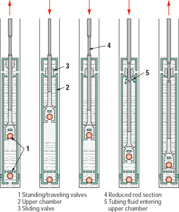 |
Fig. 7. Two-stage rod pump operation on upstroke and downstroke.
|
|
The pump is designed to load on the upstroke without an unswept volume. On the downstroke, the sliding valve closes and fluid and gas are displaced into the reduced-volume upper chamber without hydrostatic pressure against the traveling valve. Once the fluid and gas mixture has been displaced to the upper chamber, at the bottom of the downstroke the hydrostatic pressure is released by the reduced rod section to equalize pressure above and below the second stage. On the upstroke, fluid and gas are displaced into the tubing string. This operation actually uses the hydrostatic weight of the fluid to an advantage. This new pump design also has been tested, and performed remarkably well, with fiberglass rods.
PLUNGER LIFT
Three innovations for plunger-lift operations include: a stand-alone PL controller; a standing valve that relieves liquid level overloading; and a complete surface/subsurface PL package with its own lift supply.
Inexpensive plunger-lift controller. eProduction Solutions (eP), Houston, Texas, announces release of a new, inexpensive plunger-lift controller, Fig. 8. The controller’s simplistic design provides accurate control of plunger lift wells. It includes an intuitive user interface for system configuration that makes it easy to set parameters for both single-and two-valve modes. Users can easily configure high-and-low pressure overrides from a digital pressure transducer input. The unit also includes a single, high-pressure shut-down feature for use with an analog pressure transducer.
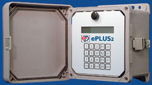 |
Fig. 8. Plunger lift controller.
|
|
The unit is designed for stand-alone operation and does not accommodate remote communication. While the unit does not include the SCADA interface that other eP controllers have, it does include an event logger that stores plunger cycle time and plunger arrivals that can be accessed through its HMI data port for analysis.
The unit is designed for use with 1- or 2-W solar panels and operates on a 6-V battery system. A smart charger/regulator system that is built into the unit extends battery autonomy and life.
Pressure-relieving standing valve. Ferguson Beauregard, Tyler, Texas, introduces a new Pressure Relieving Standing Valve, with an integrated bumper spring assembly, for relieving potentially unwanted liquid from the tubing string, Fig. 9. The idea of plunger lift is to remove as much liquid as possible from the wellbore, with the plunger arriving at surface every cycle. If an operator uses a standing valve with standard ball and seat, operations can be hindered if the fluid slug is too large. Build-up pressure in the annulus may not permit enough lift gas to bring the plunger and slug to surface, thus causing a loaded condition.
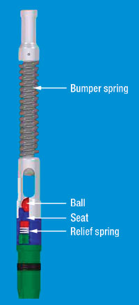 |
Fig. 9. Pressure relieving standing valve with downhole spring.
|
|
If this condition exists, having installed the pressure relieving valve will allow the operator to equalize the tubing and casing pressures at the wellhead and effectively drain liquid from the tubing. This is accomplished when the added pressure on the tubing column compresses the relief spring, moving the seat across slots that open the tubing to the annulus. A balance spring in the standing valve will cause a small fluid slug to be preserved inside the tubing string to ensure against a “dry run.” During normal operations, fluid loads are supported by pressure working upward against the seating assembly.
Complete plunger-lift package. Multi-Products Co., Millersburg, Ohio, has a joint design effort with Nitro-Lift to market the complete plunger-lift pack, which provides its own gas supply and pressure to assure removal of liquids from any well with tubing installed. A safe, clean source of lift gas means that many wells in decline can be produced at higher production levels, with what has always been a low-cost artificial lift method.
The lack of gas to assist the plunger is no longer an issue of concern to making the plunger operate successfully. Generating nitrogen (N2) at a low cost per Mcf and compressing this back into the injection line supplies pressure to lift liquids up the tubing with the plunger. Total cost of a per-well package is below that of mechanical artificial-lift forms and provides electronic controls that monitor the operation and recycle the N2 for the next cycle.
The N2 can be produced at as little as 16 cents per Mcf – this cost is even lower when the gas is recycled. The N2 generator will then be used to make-up gas for any losses to the tank or for the tank cover. The process begins with installation of the N2 processing unit about the size of an office desk. The well is equipped with the plunger-lift equipment and the controller with the monitoring system. The N2 is run through a compressor and injected into either the annulus or a side-string of small-diameter tubing.
The controls open the motor valve to the inject line and allow the pressure to accumulate to a set point in the well. They sense when lift pressure is present and open the motor valve to the separator. The separator will provide the sensing device to allow the N2 to divert back into the closed loop system for reinsertion. Gas produced by the well is sent down the sales line.
The N2 is recycled to again provide the lift, and the gas is sold through the sales line and meter. Multi provides the complete package from the N2 generator to the meter to monitor and record, as well as the plunger lift with electronic monitoring. It also provides installations to various producers with differing types of operations to achieve a high level of what limitations and situations can occur. Current cost reductions occur in lift equipment and nitrogen production.
GAS LIFT
Two equipment/electronics advances include a spoolable and retrievable downhole fiber-optic temperature profile logging system, and a unique solution for optimizing gas lift operations combining wellsite and desktop intelligence.
Fiber-optic gas lift monitor. Schlumberger, Houston, Texas, has developed a SPOOLABLE/ Retrievable downhole, fiber-optic distributive temperature system (DTS) that utilizes the same technology – and is an alternative to – its already available, permanent DTS. This system allows the operator the flexibility to spool-in the fiber optic DTS through tubing, log the producing temperature profile of the well for any given time and then remove the system.
The spoolable system is connected to the same surface instrumentation used in Schlumberger’s permanent DTS installations, and utilizes a surface optic-electronics package that contains a laser and highly sensitive optical detectors. As with the permanent system, the application is used in monitoring gas-lift operations by making use of the temperature changes caused when gas expands through the gas-lift valve downhole. The DTS allows the operator to see, at the surface in real time, which gas lift valve is operating, or if there is a tubing leak, packer leak or some other form of undesirable downhole communication. The temperature profiling system offers monitoring of the well along the entire producing string during critical operations such as start-up, well unloading, gas-lift system optimization, or any time during the production phase life.
Optimizing gas-lift operations. eProduction Solutions (eP), Houston, Texas, has developed a unique solution for optimizing gas-lift operations by combining intelligence at both the well site and the desktop, Fig. 10. At the well site, the GLO controller provides complete 24-hr local optimization. The controller performs well stability profiling, AGA 3 gas flow calculations, and constant injection control.
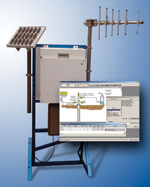 |
Fig. 10. Principal components of wellsite equipment and visual product of the Gas Lift Optimizer (GLO) controller.
|
|
Built-in sequential start-up and shutdown functions are standard to assure proper casing unloading and well kick-off. A data logger provides historic information to the on-site operator, and near-continuous information for analysis in the desktop software. The sampling frequency is variable and can be set easily with the user-friendly keyboard interface. Parameters can be set at the well site through a multi-language local interface, laptop MMI, or remotely through the host software. The controller provides eight analog and 16 digital I/O ports for extensive expansion.
The desktop intelligence portion of the solution provides real-time awareness and understanding of individual well performance. Permanent records of well history and real-time information allow the user to control, analyze and design gas-lift wells.
The software can prioritize gas allocation to high-priority wells based on total gas available. The management-by-exception methodology provides the operator a list of trouble wells rather than requiring a lengthy search. Alarms draw attention to critical well situations preventing optimal production. To analyze the wells, the operator can choose from various pressure and PVT models. Trending, reports and charts provide current and predictive analysis.
PROGRESSING CAVITY PUMPING
Two PCP advances include a new surface drive head offering performance enhancement for medium-duty applications, and new tubing rotator models providing greater application versatility.
Surface drive head. R&M Energy Systems, a unit of Robbins & Myers, Inc., Houston, Texas, has introduced the new Moyno Ultra-Drive Model CV1 downhole pump drive head, Fig. 11. This is the latest development in the Ultra-Drive “C” series drive heads designed for medium-duty, PCP applications. Significant advancements of the new design include:
- Sealing versatility that allows the end user to utilize various stuffing box configurations to meet sealing needs of a broad range of well conditions, as well as maintenance preferences and environmental requirements. The Ultra-Guard Sealing System is available as an option, offering leak-free operation, minimal maintenance and extended shaft/seal life.
- With reduced overall height, the new drive head is a more compact, lower-profile design – an important consideration when clearance is an issue, but also in terms of head stability.
- Improved balance: Overall drive head stability is enhanced because overall unit weight is centralized more directly over the wellhead. The result is improved weight distribution for drive head balance and overall stability.
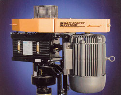 |
Fig. 11. Model CV1 downhole PCP drive head.
|
|
Electrically driven, the drive head offers rugged construction, and it features polished rod speeds to 600 rpm and a 1,600-ft-lb torque rating. It can accommodate either 1-1/4 -or 1-1/2-in. polished rods.
Tubing rotators. R&M Energy Systems has introduced new models for its RODEC line of tubing rotators, Fig. 12. Identified as the RODEC RII Series Tubing Rotators, these units provide greater application versatility for a broader range of wellheads than was previously available. A new, modular design allows the rotators to adapt to any wellhead configuration, including threaded cap as well as flanged wellheads. The new product line includes three types of systems: 1) the threaded-cap-type model in which the main body is the same for all configurations; 2) the adapter flange model that is studded down for attachment to any existing API tubing head; and 3) the Flow-T/BOP model that combines the new rotator design with a production flow tee and a rod BOP. This module can be added to any rotator of the new line.
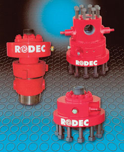 |
Fig. 12. New models of tubing rotators for PCP or beam pumping.
|
|
Additional features and benefits include: retrofit of any well with an existing tubing head; virtually no required maintenance/monitoring; units are ideal for all downhole pump types; and they maximize production and extend tubing life. The rotators provide a cost-effective solution for evenly distributing wear about the internal circumference of production tubing. Field usage shows that RODEC rotators extend tubing life by six to 10 times, reducing operating costs and downtime for maintenance. 
THE AUTHORS
|
 |
James F. Lea, Professor, Chairman of Petroleum Engineering, Texas Tech University, Lubbock, holds BS/MS degrees in ME from the University of Arkansas, and a PhD in ME from Southern Methodist University. He worked for Sun Oil Co. as a research engineer from 1970 to 1975; from 1975 to 1978, he taught engineering at the University of Arkansas; and from 1979 to 1999, he was leader of optimization and artificial lift at Amoco EPTG. He assumed his present position in 1999. Mr. Lea is a registered professional engineer in Texas; he has authored/co-authored several patents, as well as publications on artificial lift.
|
 |
Herald W. Winkler is former chairman, now professor emeritus and research associate, in the Department of Petroleum Engineering at Texas Tech University in Lubbock, Texas. He is presently working as a consultant in artificial lift, specializing in gas lift.
|
| |
|
|
 Part 2 Part 2 |
|
|

