Drilling Fluids
Drilling fluid and cementing improvements reduced per-ft drilling costs by 10%
Coordinated well design improved drilling performance by lessening wellbore washout, improving cementing practices and increasing bit performance
Doug Walton, Tom Brown, Inc., Estes Ward, Newpark Drilling Fluids, Taryn Frenzel, Schlumberger, Inc., and Harry Dearing, OGS Laboratory, Inc.
Comparing the drilling program in White River Dome field, Colorado, of 2001, in which 26 wells were drilled, with the 2002 program, in which 14 wells were drilled, shows that coordinated well design significantly improves drilling performance. Lessened wellbore washout, improved cementing practices and increased bit performance reduced costs from $77.54 per ft in 2001 to $69.56 per ft in 2002, resulting in a savings of $810,000 for the 2002 drilling program.
Use of a wellbore stabilization additive, in conjunction with a 30% reduction in circulation rate, reduced hole enlargement by an average of 14% for the interval drilled. Consisting of a reactive potassium silicate solution, the additive reduces wellbore enlargement by precipitating out of solution onto the wellbore walls. This reduced average wellbore diameter for the interval from 10.3 in. to 9.3 in. Cement volumes were reduced by 899 cu ft per well.
Improving cementing practices using a lightweight cementing system along with a more effective lost circulation additive increased cementing success from 40% to 75%. The cementing improvements complemented the improvement in hole caliper and eliminated additional costs from two-stage cementing.
Bit performance was improved from an average of 4.2 bits per well to 3.1 bits per well by use of a rate-of-penetration (ROP) additive in the drilling fluid. The ROP additive (a proprietary complex ester) provided enhanced performance when drilling bentonite stringers that had previously caused bit balling and loss of drilling rate with PDC bits.
Continued design improvements are scheduled for implementation in 2003. Evaluation of higher concentrations of the potassium silicate additive is expected to further reduce wellbore diameter. Reduction of the cement density with other design changes will lower the equivalent circulating density. Bit performance and hydraulics improvements will result in eliminating another bit per well.
FIELD BACKGROUND
White River Dome gas field in the Piceance basin of western Colorado is operated by Tom Brown, Inc., Fig. 1. It contains 67 active producing wells. The Cameo sandstones and coals are the main producing horizons and are found at depths of 5,500 to 6,500 ft.1 Since the field is on land under Bureau of Land Management (BLM) jurisdiction, a number of restrictions apply to drilling operations. One important restriction is that year-round drilling is not permitted. The drilling season usually starts in the spring and goes through the end of the year. This break allows time to evaluate results of the previous year and plan on improvements for the upcoming drilling season.
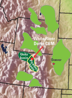 |
Fig. 1. White River Dome Field lies in the northern Piceance basin of northwestern Colorado. Production is from coals and sandstones in the Cretaceous Williams Fork formation.
|
|
With estimated reserves of 1.35 Bcf of natural gas per well and a large supply of undrilled prospects, focusing on reducing costs and improving performance pays dividends every year. Current plans are to drill 14 wells for 2003.
Establishing a good working relationship between management, geology, production and drilling personnel is the beginning point for a successful drilling season. Working with vendors of drilling services that are willing to propose new ideas and participate in their implementation is also required to achieve improvement in drilling performance. Successful coordinated well design results from selecting ideas and techniques for improvements in several drilling areas that will perform well together.
COORDINATED WELL DESIGN
For White River Dome field, a number of opportunities for improving performance were identified during the 2001 drilling season:
- Two-stage cementing increased cementing, rig and completion costs of a well by $50,000 to $75,000.
- Hole washout in the upper section below surface casing required large cement volumes and increased the likelihood of lost circulation during cementing.
- Due to the extensive fracture treatments anticipated for the wells, primary cementing success (as measured by cement bond logs) was a requirement for drilling success.
- PDC bits performed very effectively, with average ROPs of more than 100 ft/hr in most wells. Increasing footage drilled by PDC bits would result in fewer bits, higher ROPs and lower drilling costs.
RIG SELECTION
For this project, a Tom Brown subsidiary, Sauer Drilling, provided the rigs. The rigs were moderate-depth, conventional rotary rigs rated to 10,000 ft with 4-1/2-in. drill pipe fitted with at least one triplex mud pump.
BIT SELECTION AND HYDRAULICS
During the past three years, wellbore design for drilling wells at White River Dome field involved:
- Drilling 11-in. hole to 1,100 ft (gel/lime spud mud)
- Running 8-5/8-in. surface casing (cement to surface)
- Drilling 7-7/8-in. hole to TD (water and LSND mud)
- Running 5-1/2-in. casing (cement to surface).
Top of cement behind the 5-1/2-in. production casing must be above the surface casing shoe to cover shallow water and gas flows in the Wasatch formation. Lost circulation and hole washouts cause problems toward achieving an acceptable top of cement. Sloughing shales in the Wasatch cause hole washouts, and consequently, large cement volumes. Lost circulation problems exist during cementing due to breakdown of deeper sand and coal seams through the Cameo formation. Due to problems with lost circulation during cementing, lightweight cement with a compressive strength above 2,000 psi was used to achieve a top of cement above the surface casing shoe. With the higher-cost slurry, a reduction in the cementing volume was necessary to reduce well cost.
The Wasatch is drilled with water and a PDC bit, which is typically pulled for bit balling problems after drilling through a bentonite stringer in the Mesa Verde/Williams Fork formation. Mud-up with an LSND mud occurs prior to pulling the PDC and the well is then drilled to TD (6,200 to 7,200 ft) in the Rollins formation with as many as three three-cone bits.
To improve bit life, increase ROP and reduce hole washouts, several changes were made over the past two years to the mud program, bit selection and drilling hydraulics. To reduce hole washouts during the 2001 drilling program, circulating rate during drilling of the 7-7/8-in. hole was reduced by 28% from 460 gpm to 330 gpm. This reduced annular velocity from 270 fpm to 193 fpm. Hole washouts were reduced slightly (by ± 1/2-in.) due to reduced circulating rate without any loss of ROP, despite a drop in hydraulic horsepower per square inch (HSI) at the bit. During 2003, jet sizes will be reduced during drilling with PDC and three-cone bits to increase HSI to between 2.5 to 5 in an attempt to improve ROP and reduce bit balling.
During 2002, several changes were made concerning bit selection and mud design. The typical PDC design used during 2000 and 2001 was a 6-blade, 3/4-in.-cutter bit., whereas during 2002, a switch was made to a 5-blade, 5/8-in.-cutter design in an attempt to improve on PDC durability for a longer run time. In addition to the PDC change, an ROP additive (a polyglycerol ester) was added to the mud system to reduce problems with bit balling while drilling bentonite stringers. The change in PDC design and ROP additive resulted in longer PDC bit runs and elimination of just over one three-cone bit run per well. Elimination of one bit trip and the enhanced ROP reduced average time on location by one day between 2001 and 2002.
During 2000 and 2001, a potassium chloride (KCl) substitute was added to improve shale stability while drilling through the Wasatch. While the KCl substitute did help reduce washouts in the shale, average hole size through the Wasatch was still over 10 in., which meant that the KCL substitute did not effectively reduce cementing costs. A different approach to stabilize shales involving potassium silicate during the water section of drilling was implemented during the 2002 drilling program. The addition of potassium silicate successfully reduced hole size, resulting in an average 28% reduction in cement volume as compared to prior years.
DRILLING FLUID
Interest in silicate-based drilling fluids, which have been used in a number of areas over the past 50 years, waned from the 1950s until the mid 1990s.2 However, renewed interest has led to their use in a number of drilling fluid applications in various regions.3,4 These applications are usually with fully formulated drilling fluids containing high concentrations of silicates in combination with other inhibitive salts.
Analysis of well calipers obtained from wells drilled during 2001 showed that most hole enlargement occurred in the portion below surface casing to about 4,000 ft TVD. This was also the section that was drilled with water while circulating the reserve pit. This resulted in high ROPs with a PDC bit and low cost per foot.
Experience in the area suggested that the hole washout could be reduced by mudding up in this interval with a partially hydrolyzed polyacrylamide (PHPA) mud. Experience also showed that this would result in increased mud costs and lower ROPs. For these reasons, an alternate strategy was required.
The continuous injection of potassium silicate solution into the mud pump suction at 0.1% of the drilling pumping rate was proposed. This would result in a low-cost treatment of the wellbore as drilling progressed and not compromise drilling rate. Prior to mudding up at 4,000 ft, the addition of silicate would be discontinued and the silicate allowed to deplete from the fluid. The silicate selected for this application has the properties shown in Table 1.5
| |
Table 1. Properties of potassium silicate |
|
|
Density |
10.5 ppb |
|
|
K2O |
8.3 wt% |
|
|
SiO2 |
20.75 wt% |
|
|
Ratio, %SiO2 /% K2O |
2.5 |
|
|
Viscosity |
40 cPs |
|
|
Solids |
29.05 wt% |
|
|
The reaction between the exposed wellbore and potassium silicate occurs because the lower pH of the wellbore surface and presence of divalent cations, calcium and magnesium cause precipitation of a hydrous silicate gel. These gels act to seal the wellbore surface, increasing its stability. Potassium silicate was chosen over sodium silicate for two reasons. Potassium silicate is soluble at a lower pH than sodium silicate. Also, the potassium ion has proven to inhibit clay swelling. The presence of quartz (crystalline SiO2) in the sands and shales on the exposed wellbore provides preferential sites for bonding of the silicate.
In addition to potassium silicate, control of pH with caustic potash (KOH) at 10.5 was recommended. It was also anticipated that high viscosity sweeps would be pumped as needed to facilitate hole cleaning.
The fluid design was developed to address the problem of wellbore enlargement without affecting ROP and minimally increasing mud cost. After discussion and review, use of the silicate was approved for the 2002 drilling season. Sufficient product for several wells was ordered and maintained in stock.
CEMENT DESIGN
The design of an effective cementing system is especially critical to the success of these wells. Since coal sections are to be stimulated separately from the sandstone sections, zonal isolation is very important. Thus, the entire cementing process was examined critically and several possible cement designs examined:
- Conventional cement using industry standard additives for density control
- Nitrogen foamed cement
- Lightweight cement using proprietary density reduction solids.
The previous field operator’s experience using conventional cements indicated that a lower density slurry was required. This left the other two options. Both systems were designed and evaluated.
Foamed cement design. A nitrogen foamed cement system was pumped on one well with a design based on 10% excess over the caliper log as follows:
- 155 bbl of 10-ppg foamed lead cement
- 75 bbl of 13-ppg foamed tail cement
- 15 bbl of 14.3-ppg non-foamed tail
- Treated water displacement to bump the plug.
Job planning included the logistics for nitrogen handling equipment.
Lightweight slurry cement design. The first challenge was to overcome the hydrostatic restrictions with a lightweight slurry that still developed sufficient compressive strengths to provide zonal isolation for future fracture treatments. This was accomplished using Schlumberger’s LiteCRETE technology consisting of an optimized particle-size-distribution slurry.6 An 11.27-ppg system that achieved 2,300-psi compressive strengths was designed for the project. This production-quality cement was used for the tail system following an 11-ppg conventional filler cement, which was used to cover the sands up to surface pipe. This lead and tail system, achieved an ECD less than the frac gradient of 0.61 psi/ft (equivalent density = 11.7 ppg), as seen in Fig. 2.
 |
Fig. 2. ECD data for LiteCRETE system.
|
|
With hydrostatic goals achieved, a more effective LCM was needed. A fiber-type LCM was chosen (CemNET) because of its success in cementing across fractured coals in other areas, which not only helped maintain returns, but also reduced the amount of excess cement needed on the jobs and minimized cement fallback when pumps were shutdown. In addition to running the fiber-type LCM, it was also decided to drop the top plug on the fly. The thought was to minimize surging on the formation caused from the annular velocity slowing down then abruptly accelerating back to surface pump rates.
DRILLING FLUID RESULTS
The Ant Hill Unit 25 – 22 was the first well drilled using the silicate additive to supplement water. After drilling and setting surface casing, a Smith M75VPX bit was used to drill out. As soon as cement had been drilled, the silicate solution was added to the water in the suction pit at a rate of 0.5 gpm (0.15 % of the circulation rate).
As drilling proceeded, silicate solution7 concentration in the water at the pump suction and flowline was monitored with the pH and potassium level. Fig. 3 shows the silicate solution concentration in the water at the flowline and suction.
 |
Fig. 3. Silicate concentration in drill water.
|
|
As indicated, there was significant depletion of the silicate solution in the well. Average silicate concentration for the suction pit was 0.14 wt% for the interval. Average flow line concentration was 0.10 wt%. This indicates that the reaction of the silicate with the wellbore and cuttings was proceeding rapidly, even at the low concentrations used. Also note the rapid depletion of the silicate when additions were discontinued at about 3,200 ft.
Typical calipers for two wells, one from 2001 and one from 2002, are shown in Fig. 4. The main reduction of enlargement came from under surface casing to about 4,000 ft – the interval drilled with water and silicate additive.
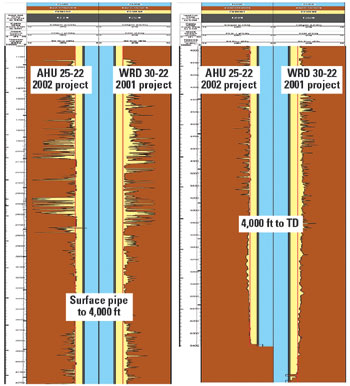 |
Fig. 4. Caliper comparison between typical wells for 2001 and 2002.
|
|
For the 14 wells drilled in 2002, the caliper averaged 9.4 in. In 2001, it averaged 10.5 in. Most of this improvement occurred in the sections drilled with water and the silicate additive.
CEMENTING RESULTS
At the end of 2001, this lightweight design was implemented and had early success (60%) and effectively eliminated two-stage cementing. In one of the trial wells, annular returns stopped, but were regained and a successful cement treatment was achieved. The fact that returns were regained was proof that the new LCM chosen was more effective in packing off the fractures than the previous coarse particle.
In 2002, a single-stage foam treatment was attempted, which proved unsuccessful due to a permanent loss in returns during flush. The foamed cement job was pumped at an average of 6 bpm with 1,000 psi surface pump pressure. Returns diminished during flush down to a 14 bpm pump rate with no cement returns to surface. A cement bond log prior to completion showed top of cement at ± 3,100 ft. Thixotropic cement at 14.6 ppg was pumped down the 858-in. by 512-in. annulus as a cap. The foamed cement job was comparable in cost to prior two-stage cement jobs, and did not achieve an acceptable top of cement without additional work and expense.
For these reasons, it was decided to stay with the LiteCRETE/CemNET system and focus on increasing success from the test wells. In 2002, eight wells were cemented using this combination, and six of the wells (75%) maintained returns, which led to successful treatments. Not only was the success ratio increased from the 2001 conventional treatments, but the additional costs associated with 2-stage cementing had been eliminated. With the successful hole diameter reduction that occurred in 2002, the cement volume was reduced by an estimated 899 ft3 (160 bbls) per well. If this eight-well average was applied to all 14 wells in the 2002 project – this equates to a reduced cement volume of 2,232 bbl and a material cost savings of over $150,000 for the project.
ROP ENHANCEMENT
As stated in the hydraulics section, the PDC bit runs in the 7-7/8-in. hole sections consistently ended with bit balling in the bentonite stringers of the Mesa Verde/Williams Fork formation at around 4,000 ft. If bit balling could be reduced, the PDC bit runs could probably be extended by as much as 1,000 ft.
This situation was ideal for the application of an effective ROP enhancer. This product is based on a Newpark Drilling Fluids proprietary complex ester. It was found that the additive immediately cleaned the bit and increased ROP to the same level as prior to bit balling. Typically, the additive was used in slugging treatments to aid in drilling bentonite stringers. Over time, as much as 2 vol% of the additive was used in the active mud system. As stated earlier, application of the ROP enhancer with a more aggressive bit design eliminated one three-cone bit and reduced time on location by one day.
SUMMARY OF WELLS
Table 2 gives a summary of the results obtained in 2002 compared with 2001.
| |
Table 2. Summary of well results |
|
|
|
2001 |
2002 |
|
|
Number of wells |
26 |
14 |
|
|
Dry hole cost, $ |
540,321 |
503,945 |
|
|
Well depth, ft |
6,968 |
7,245 |
|
|
Cost/foot, $ |
77.54 |
69.56 |
|
|
Days to depth |
13.6 |
12.2 |
|
|
Mud cost, $ |
31,177 |
26,977 |
|
|
Hole diameter, in. |
10.5 |
9.4 |
|
|
Tail cement volume, ft3 |
790 |
528 |
|
|
Lead cement volume, ft3 |
2.343 |
1,706 |
|
|
As can be seen, there was improvement in every aspect of the drilling operations from 2001 to 2002. Improved hole conditions also resulted in improved cementing performance. The goal of maintaining circulation throughout the cement job was achieved on six of the eight comparable wells in 2002 (a 75% success rate) compared to only six of 15 comparable wells for 2001 (a 40% success rate).
Application of the new drilling technologies reduced well costs across the board – including mud and cementing costs. This suggests that, in this case, the application of new technology in a mature area can improve performance and reduce well costs.
CONCLUSIONS
Coordinated well design has provided substantial cost savings in the White River Dome field for Tom Brown, Inc. Working in concert, several innovative new technologies have contributed to these cost reductions:
- Reactive potassium silicate reduced wellbore enlargement without sacrificing ROP or cost.
- Improved bits and hydraulics eliminated one bit and one day from the days to TD.
- Improved lightweight cement slurries provided excellent cementing performance with the application of new lost circulation products.
- ROP enhancing drilling fluid additives allowed longer and faster PDC bit runs.
IMPROVEMENTS FOR 2003
A number of potential improvements will be evaluated in 2003, including:
- Varying the silicate content of the water drilling portion of the hole to further reduce wellbore enlargement
- Improved bit designs to reduce the number of bits per well from the current average of about three to two
- Further refine the application of lost circulation products and lightweight cement to improve cementing success to 100%.
The success in the 2003 cementing program can be improved by studying the successful wells. Plotting the results of hole diameter vs. success shows that when the lead section’s average diameter was less than 9.25 in., then 100% success was observed. If the lead section was greater than 9.25 in., then 33% success was observed. This correlation suggested that the losses in returns might have had something to do with the section at 2,500 ft that tended to be severely washed out. Further evaluation of this trend will be studied to fully understand the results. Improving the caliper in this section should directly benefit cementing success.
A second step to increase success in 2003 will be to lower the cement slurry densities. A new LiteCRETE system has been designed that has a 10.5 ppg density. With this lower density, the compressive strengths will peak around 3,000 psi. A 10.5-ppg conventional filler lead, which has properties similar to the previous 2002 lead system, also will be used. With these changes, the ECD in the well will be reduced by 0.7 ppg (from 0.6 psi/ft to 0.56 psi/ft). As seen in Fig. 5, this increases the fracture pressure safety margin, which should lead to an increase in cementing success for 2003. 
 |
Fig. 5. Equivalent circulating density improvement for 2003 versus 2002 design.
|
|
ACKNOWLEDGMENTS
The authors thank Tom Brown, Inc., Newpark Drilling Fluids and Schlumberger, Inc., for their support. We also appreciate the field personnel who worked to implement the coordinated design for this project. They include Curt Childers, Consulting Drilling Supervisor; Don Jackson, Newpark Drilling Fluids; Tony Kenyon, Newpark Drilling Fluids; Garth McConkie, Schlumberger; and rig personnel, Sauer Drilling Co.
REFERENCES
1 Olson, Terrilyn; Hobbs, Bill; Brooks, Robert; and Gale, Byron: “Paying Off For Tom Brown In White River Dome Field’s Tight Sandstones, Deep Coals,” American Oil and Gas Reporter, December 2002, pp 67 – 75.
2 Darley, H.C.H., Gray, George R.: Composition and Properties of Drilling and Completion Fluids, 5th Edition, March 1998, pg 381.
3 D’Alessandro, Fulberto: “An inhibitor system for drilling active clays,” World Oil, April 2001, pg E-39.
4 Rawlyk, Dave; McDonald, Michael: “Potassium Silicate Based Drilling Fluids: An Environmentally Friendly Drilling Fluid Providing Higher Rates of Penetration,” CADE/CAODC Drilling Conference, Calgary, Alberta Canada, October 23 & 24, 2001.
5 Kasil® 1 Product Specification Sheet, PQ Corporation, November 1998.
6 Hun, Christian; El-Hassan, Hassan; Helou, Husam; Hasni, A. Latif; Mohsen, A. Hammeed: “Innovative Solution for Cementing Across Very Low Fracture Gradient Formations,” IADC/SPE 72286, Middle East Drilling Technology Conference, Bahrain, October 2001.
7 “Field Test Method for Silica Content in a Potassium Silicate Drilling Fluid,” National Silicates.
THE AUTHORS
|
 |
Doug Walton is an operations engineer for Tom Brown, Inc., in Denver, Colorado. His areas of responsibility include the Piceance basin in Colorado and the Green River basing in Wyoming. He holds a BS degree in petroleum engineering from West Virginia University.
|
 |
Estes Ward, operations manager for Newpark Drilling Fluids, Rocky Mountain Business Unit, provides drilling fluid recommendations for wells drilled in the Rocky Mountains. He has 25 years of experience in the Rocky Mountains as a field mud engineer, senior fluids engineer and manager.
|
 |
Taryn Frenzel, a Schlumberger well services engineer of Denver, is working in the Tom Brown office as a DESC engineer. He holds a BS degree in engineering science from Montana Tech of the University of Montana.
|
 |
Harry Dearing manages OGS Laboratory, Inc. (a Newpark Resources company). As laboratory manager, he works in the areas of fluid design, product evaluation, and shale stability testing. Prior to rejoining OGS Laboratory in 1998, he worked for a major oil company in various positions, most relating to drilling fluids. He has a degree in engineering from The University of Texas - Austin.
|
| |
|
|

