Casing drilling proves successful in South Texas
New Drilling TechnologyCasing drilling proves successful in South TexasCompared to conventionally drilled wells, drilling wells with casing is proving to be more efficient, reducing downhole problems and generating substantial time and cost savingsKyle Fontenot, Conoco Inc.; and Tommy M. Warren and Bruce Houtchens, Tesco Corp. Conoco has used Tesco’s Casing Drilling* system to drill 17 development wells in Lobo field of South Texas since mid-2001. The intermediate and production sections of Lobo wells often require time for hole conditioning, lost circulation, gas influxes, stuck pipe and running casing. The system has significantly reduced these downhole problems by casing the well as it is drilled. This is accomplished by using casing as the drill pipe. Once the casing point is reached, the casing is cemented in place without tripping pipe, unless the production casing is partially tripped for openhole logs. Negligible time has been required for hole conditioning and lost circulation. Gas influx has been less of a problem while drilling with casing than when drilling conventionally. Performance on the first 10 casing drilled wells shows that the technology provides time savings of 8% to 33%.** This system’s potential for reducing drilling time and cost was sufficiently obvious after drilling the first few wells. So, Conoco entered into a two-year contract for three new casing drilling rigs to be delivered by the end of 2002. Full economic impact of this technology on Lobo drilling will not be realized until these rigs are in place. Current Efficiency Cycle The operator significantly increased its Lobo trend holdings during the mid-1990s. Currently, the company produces 520 MMcfgd from the trend. In 1997, Conoco embarked on an active field development program that set a goal of drilling 1,000 wells over seven years. By 2001, 10 rigs were employed to drill 160 wells annually. However, drilling efficiency stagnated, Fig. 1.
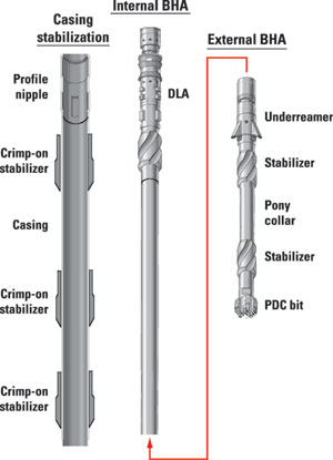
Great strides had been made in increasing ROP, drilling each hole section with a single bit and in improving general rig operation efficiency. The most significant thing that limits the ability to reduce days on each well is the time to prevent and recover from downhole problems. Although well control and a failure to successfully run the 7-in. casing were significant in 2001 and 2000, respectively, stuck pipe and lost circulation were by far the most consistent contributors to Lobo well problems. It became clear that conventional drilling optimization had hit a plateau. An initiative was begun in 2001 to further reduce drilling costs – specifically, to reduce costs enough to allow reservoirs smaller than 1.0 Bcf of gas to be developed. This would extend development potential for several years. Drilling with casing was identified as the item potentially providing the greatest value toward continued cost reductions. Conventional Drilling The 9-5/8-in. surface casing for Lobo wells is set at 550 to 1,500 ft, depending on the freshwater level, and the entire operation is quite efficient. Few problems are encountered in this section. An integral wellhead system minimizes flat time at casing points. The most significant benefit of drilling with casing for this section is that it provides a more efficient process, particularly for deeper surface holes. Drilling the 8-3/4-in. intermediate hole section is somewhat more problematic, although the instantaneous ROP is quite high, and the section can be drilled with a single bit. Weak zones are encountered in the Queen City formation (3,500 to 6,000 ft), where it is easy to lose circulation. Mud weight up to about 11 ppg is required to control the gas at the TD of this section, where casing is set into the transition to the geo-pressured zone. A combination of differential sticking, packing off and mechanical sticking accounts for most of the Lobo stuck pipe incidents. To deal with this situation and assure that casing can be run to bottom, a short trip is usually conducted while conventionally drilling the interval. A wiper trip is made before running casing. Deviation control problems, due to formation dips and faults, require motor correction runs in some wells. In other cases, directional work is planned to hit a defined bottomhole target. Once intermediate casing is set, a switch is made to oil-based mud, to better deal with the temperature (300°F) and high mud weight (15 ppg) used to drill the pay sands. Drilling the 6-1/4-in. production hole goes quite well, although conditioning for well control, logging and running casing can take longer than drilling the hole. Reducing Flat Time Any major reduction in drilling time had to address flat time rather than making hole time. Significant flat-time periods were associated with keeping and protecting the hole, trouble time (which averaged about 1.5 days per well) and casing running operations. Flat time averaged about 45% for Lobo wells, compared to typical values of 44% to 86% for all wells, and 65% for onshore wells.1 This indicates that conventional drilling performance on these wells is quite good. Drilling with casing can reduce flat time by eliminating drillstring tripping and hole conditioning required before running casing; eliminating casing running time; and reducing the risk of not getting casing to bottom. The most significant unknown for Lobo wells was whether drilling with casing would mitigate stuck pipe and lost circulation issues. Based on results in a less severe situation, it appeared that overall borehole quality could be improved, to reduce both borehole stability and lost circulation.2 In addition to directly impacting drilling efficiency, the system was also expected to improve well safety. Well control is improved, because the casing remains in the hole at all times. Thus, there are fewer operations where the well cannot be circulated. Reduced pipe handling and tripping also reduced the time spent on activities that have higher, accident frequency rates. The contractor’s system for drilling with casing was chosen for a five-well pilot project. The work would evaluate both the technology and its potential to impact particular problems encountered at Lobo. This is the only system of its kind that is commercially available to provide retrievable bottomhole assemblies that allow bit changes and directional work without tripping the casing. Casing Drilling Process The casing drilling system comprises downhole and surface components that allow the use of normal oil field casing as the drill string, so that the well is simultaneously drilled and cased.3 The casing provides hydraulic and mechanical energy to a wireline-retrievable drilling assembly suspended in a profile nipple near the bottom of the casing. The casing is rotated from the surface, and the drilling fluid is circulated down the casing ID and back up the annulus. The bottom joint of casing, along with the wireline retrievable components residing inside the casing and extending below the casing shoe, can be seen in Fig. 2.
A drill lock assembly (DLA) in the BHA’s top provides mechanical (axial and torsional) coupling and hydraulic seals to the casing. The DLA has a locator mechanism, an axial lock, and torsional drive splines that mate with a profile nipple at the first casing joint’s top. It also provides a mechanism to facilitate insertion and retrieval. The drilling assembly below the DLA terminates in a pilot bit, but may include other conventional drill-string components, such as an underreamer, mud motor, coring or directional assembly. In most drilling with casing applications, an underreamer is used above the pilot bit to open the hole from the pilot bit diameter to the final wellbore diameter. The pilot bit is sized to pass through the casing, and the underreamer opens the hole to the size that is normally drilled to run casing. For example, a 6-1/4-in. pilot bit and 8-1/2-in. or 8-7/8-in. underreamer are used while drilling with 7-in., 23-ppf casing. (In some situations, it might be desirable to use a bi-center bit instead of an underreamer. Generally, however, the ratio of drilled diameter to pass-through diameter is too small for this application.) The system utilizes a top drive to rotate the casing. The casing string is rotated for all operations, except slide drilling with a motor and bent housing assembly for oriented directional work. The casing string is attached to the top drive via a casing drive system (CDS) without screwing into the top casing connection. The CDS includes a slip assembly to grip the pipe exterior and an internal spear assembly to provide a fluid seal to the pipe. It is operated with the hydraulic top drive control system. Use of the CDS speeds up the casing handling operation and prevents damage to the threads by eliminating one make / break cycle. Drillers Tech 4, designed as a dual-purpose (drill pipe and drilling with casing), all-hydraulic rig, is used for the project.4 This rig is not optimal for the particular wellhead and muds used on Lobo wells, but it provides the ability to drill with casing and allows good evaluation of the technology Casing with buttress threads is used for the 9-5/8-in. surface and 7-in. intermediate hole sections. A torque ring installed in each coupling in the field increases the coupling’s torque capacity. A special coupling (DWC-C), designed by a major connection manufacturer for drilling with casing, is used on the 4-1/2-in. production casing. Lobo Performance The program was initiated with a five-well pilot project to evaluate the technology for drilling Lobo wells. A number of challenges were overcome during this program:
By the time the five-well pilot program was completed, drilling performance had improved sufficiently to match that of conventional drilling. This occurred even though there was obviously considerable room for further improvement of the performance. Sufficient progress had been made, and potential demonstrated, so that the program was extended for all of 2001. The five well pilot program was critical to the determination that drilling with casing is economically viable for Lobo field. Had a single well test program been undertaken, instead of making committing to multiple wells, it is doubtful that the program would have been extended past the first well. Surface and intermediate hole sections. For the first 11 wells, the time required to drill surface and intermediate sections from spud until the 7-in. casing was landed on bottom is shown in Fig. 3. Performance on the first wells was considerably less than desired, but a steady learning curve was demonstrated for the wells drilled with casing. (Well 8 was drilled conventionally.)
The fifth well matched average performance of 113 similar wells drilled by seven rigs during 2001. Drilling progress averaged 1,032 ft/day for the last five wells drilled with casing, compared to 777 ft/day for conventional wells. This is equivalent to a two-and-a-half-day advantage for the casing drilling system at the average intermediate casing point of 7,700 ft. ROP for surface and intermediate hole sections drilled with casing (excluding the first three wells, where deviation control issues were being resolved) was slightly better than the average performance of the seven conventional rigs drilling similar Lobo wells during 2001, Fig. 4.
While this indicates that ROP is not sacrificed while drilling with the pilot bit and underreamer, it also shows that there is room for improvement. Since the main advantage of the new system is to eliminate flat time, it is imperative that ROP be maintained, so that this advantage is not offset by slower hole-making performance. After seven wells were drilled with casing, the eighth well was drilled with conventional drill pipe and collars. Then, the remainder of the wells were again drilled with casing. This eighth well was very similar to Well 7 and provides a good comparison of the system’s advantages. Both wells were drilled to similar depths and had a planned directional section at the bottom of the intermediate hole section. Table 1 compares the two wells, overall. Well 7 was drilled to the kick-off point of 6,000 ft. Then, the packed BHA was pulled with the wireline, and the directional motor assembly was run on the wireline. Drilling continued to casing point and achieved directional objectives. No drilling difficulties were encountered in either the surface or intermediate hole sections.
The directional drilling BHA used with the system consisted of:
Well 8 was conventionally drilled to 3,100 ft, where it lost circulation. After pumping numerous LCM pills, the drillstring was tripped out and cement spotted across the lost circulation zone. Drilling resumed 47 hr after losing circulation. In this particular comparison, drilling with casing resulted in the 7-in. casing reaching the casing point 3.2 days ahead of conventional drilling. Eliminating trouble time accounted for two days of the difference, and one day was normal flat time associated with conditioning the hole, tripping the drillstring, and running the casing. This time comparison is similar to overall averages, Fig. 3. This example points out a non-intuitive result of using the system. A higher ECD from the reduced annulus would normally be expected to cause more lost circulation while drilling with casing than when drilling with a conventional drill-string. In fact, just the opposite seems to be true. Lost circulation has not been a problem, and there have been no instances of the casing becoming stuck for wells drilled with the new system. Drag coming off the slips is less than for a conventionally drilled well. When the casing had to be tripped because of DLA failures in the early wells, the casing could be tripped with less openhole problems than could the drill pipe and collars on conventional wells. With the limited data available, it appears that drilling with casing appears to yield a more stable, less permeable wellbore than what is achieved traditionally. Hypothetically, the casing mechanically conditions the wellbore wall to create a strong, impermeable surface finish. This may be accomplished by mechanically "plastering" the wellbore wall with solids from drilled cuttings and the mud. This does not prevent the bit from encountering loss zones, but the loss can often be treated and cured while drilling ahead. This not only helps prevent and cure lost circulation, but also allows lower mud weight to be used to control gas influx on connections. For example, Table 2 compares mud densities used at intermediate casing point for four wells drilled with casing, compared to their closest offsets.
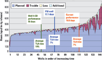
Noticeable wear on the 7-in. casing couplings was experienced on the first two wells, but employing a combination of wear rings and casing centralizers eliminated the wear. Solid body centralizers are attached to the lower part of the casing to provide stabilization and satisfy regulatory requirements. Below each coupling, hard-faced wear bands are installed for the bottom portion of the 7-in. casing string. Both the centralizers and wear bands are installed with a field-applied hydra-forming process. Lobo wells are drilled in an area where deviation control can be a problem. Some wells are directionally drilled intentionally to short displacement targets. Deviation control was a significant challenge on the first three wells drilled with casing, but changes in the retrievable BHA eliminated these problems. In cases where directional drilling is needed, the rotary assembly is pulled at the KOP, and a steerable motor assembly is run on the wireline. The first three wells were drilled with the stabilization for deviation control placed on the casing exterior. The first two wells were stabilized to provide a "packed" assembly. The third well used a pendulum assembly, similar to what is used when drilling conventionally. Neither of these strategies proved workable. Not only did the stabilization experience excessive wear, but it did not control the deviation. The fundamental deviation control strategy changed for the fourth well. A packed hole assembly was designed to run in the pilot hole and the underreamer was run on top of the packed assembly. This assembly was laterally uncoupled as much as possible from the casing. The deviation control achieved with this assembly was as good, and possibly better, than can be achieved while drilling with a conventional drill pipe / drill collar assembly. The intermediate hole section was drilled with both straight hole motors and by rotating the casing. The motors were used to reduce casing wear and increase ROP. It was found that the casing had to be rotated at speeds of at least 80 rpm to mitigate torsional vibrations, while the improvement in ROP was marginal. Rotating the casing proved to be the most cost-effective way of drilling intermediate sections. For 2000 and 2001, 75% and 85% of overall trouble time, respectively, was attributed to open-hole causes, such as stuck pipe, well control and lost circulation. While drilling with casing, there have been no incidents of stuck pipe and lost circulation. Well control events have been minimal. Only about 2% of time lost while drilling with casing is traceable to openhole causes. This has been achieved with a mud cost no higher than for conventional wells. While there has been a fair amount of trouble time, particularly in the first few wells, almost all of it has been associated with mechanical equipment. As with any new technology, these problems are frustrating, but ultimately they are easier to deal with than formation-related downhole problems. Surface section of each casing drilling well has been drilled with a single, wireline-retrievable BHA that has been retrieved successfully. In the first four wells, there were several intermediate hole incidents. These involved an inability to retrieve the drilling assembly on wireline, requiring casing to be pulled. Since then, however, more than 70 BHAs have been run in the Lobo wells without a failure to successfully retrieve them. These assemblies include straight hole-drilling BHAs, and directional motor and MWD assemblies. BHAs have been retrieved from as deep as 8,997 ft, after runs as long as 112.5 rotating hr, and after drilling as much as 7,172 ft with a single run. Production hole section. Production hole intervals in the first 10 casing wells were drilled conventionally, because a drill lock was not available for the particular combination of oil mud, high temperature and casing weight needed. Experience gained on these wells indicated a potential benefit to drilling these intervals with casing. For example, Well 10 was drilled with casing to an intermediate point of 8,997 ft, and the casing was cemented in 9.1 days. After drilling out cement, the well was drilled to an 11,600 ft TD with drill pipe and collars in three days (45.5 rotating hr). The next 6.5 days were spent dealing with a combination of well control and lost circulation (67.5 hr); tripping in and out with drill pipe and laying down drill pipe (48 hr); logging (6.5 hrs); and running and cementing 4-1/2-in. casing (27.5 hr). As an alternative to the retrievable system, a releasable bit scheme was developed and used to drill the production hole sections of the remaining wells, now completed. A combination near-bit stabilizer / float / bit sub was designed, so that a ball could be dropped to release the bit at TD. Casing was left fully open, once the bit was released. Logging was not required for some wells, and the casing was simply cemented in place once TD was reached. For other wells, the bit was released and the casing tripped back to the intermediate casing shoe, so the entire production interval could be logged with a complete suite of electric wireline measurements. Using this method, Well 15 was drilled in a near-record 10.4 days (spud to rig release). Although this procedure required some pipe tripping, it still involved less tripping than when the interval was drilled conventionally. It also provided the capability to circulate the hole at the bottom of the intermediate casing. Potential Impact Data from the first few wells drilled with casing were analyzed and compared to conventional drilling, to gauge the value of drilling Lobo wells with casing. Historical performance of conventional wells drilled since 1998, in the depth range expected for wells this year (10,500 to 11,500 ft), is shown in Fig. 5.
The median well was drilled in 17.1 days. However, current drilling performance, based on 20 conventional wells drilled in this depth range since Sept. 1, 2001, is 19.8 days to drill to an average depth of 11,009 ft. These 20 wells incurred an average of only 7% lost time (as did the P50 well). Totally eliminating all trouble time would only reduce average drilling time by 8% to 9%. This indicates that the fundamental drilling system must be changed to provide significantly improved drilling performance. Certain normal activities take less time when drilling with casing for conventional wells, so that a casing drilled well will be somewhat faster when both are drilled with no lost time. A reasonably conservative estimate of time reduction for normal activities on a typical Lobo well is about 1.5 days (8%), based on performance to date. Performance data also show that the in-hole trouble time is less when drilling with casing. The exact reduction in trouble time is difficult to quantify because of the relative infancy of the new process at Lobo, and the fact that the full process has not been implemented. Sufficient data are available to support a reasonable expectation that the trouble time can be reduced 50%, as compared to conventional drilling. Historical data generated probability curves for the time required to drill a well conventionally, including and excluding trouble time, Fig. 6. Variation in drilling time for the fastest 50% of the conventional process is mostly affected by normal variation in formation conditions and unidentified efficiency variations. Significant trouble time is identified for the slowest 50%.
The curve, "casing drilling 50% trouble," is the expected drilling performance when the drilling with casing process is fully implemented. It indicates a time reduction of 16% for the average well. The yellow-shaded area is the expected savings from employing the process for all wells, based on results achieved to date. A lower curve, "casing drilling, no trouble, no logs," shows that a 33% time reduction could be achieved at the technical limit, if all trouble time were eliminated and no openhole logs were run. Although most wells require openhole logs, there is a movement to reduce this requirement for logs in future Lobo development wells. Comparison of conventional wells’ performance to wells drilled with casing indicates substantial savings. These results were used to justify expanding the casing drilling program by contracting for three custom-designed rigs to be built and committed to a two-year Lobo drilling program. Acknowledgment This article is based on a paper originally presented at the IADC World Drilling Conference, Madrid, Spain, June 5 – 6, 2002. Literature Cited 1 DEA, "Flat time reduction opportunities," Houston, Texas, Sept. 21, 1999. 2 Shepard, S. F., Reiley, R. H. and T. M. Warren, "Casing drilling successfully applied in southern Wyoming," World Oil, June 2002, pp. 33Ð41. 3 Tessari, R. M., et al, "Drilling with casing promises major benefits," Oil and Gas Journal, 1999, Vol. 97, No.20, p. 58. 4 Laurent, M., Angman, P. and D. Oveson, "Hydraulic rig supports casing drilling," World Oil, Sept. 1999, p. 61.
|
||||||||||||||||||||||||||||||||||||||||||||||||||||||||||||||||||||||||||||||||||||||||||||||||||||||||||
- Applying ultra-deep LWD resistivity technology successfully in a SAGD operation (May 2019)
- Adoption of wireless intelligent completions advances (May 2019)
- Majors double down as takeaway crunch eases (April 2019)
- What’s new in well logging and formation evaluation (April 2019)
- Qualification of a 20,000-psi subsea BOP: A collaborative approach (February 2019)
- ConocoPhillips’ Greg Leveille sees rapid trajectory of technical advancement continuing (February 2019)

