What's new in artificial lift
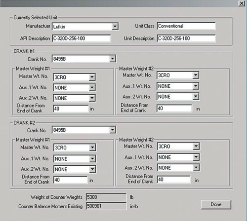
ARTIFICIAL LIFTWhat’s new in artificial liftPart 1 – Fourteen new systems for beam, progressing-cavity, plunger-lift pumping and gas liftJames F. Lea and Herald W. Winkler, Texas Tech University, Lubbock, Texas; and Robert E. Snyder, Contributing Engineering Editor Described here are 14 recent developments in four categories of artificial lift technology, including: beam pumping (8 items); progressing-cavity pumping (PCP) (3); plunger lift (2); and one gas-lift related item. Part 2, coming in the May issue, will present electrical submersible pumping (ESP) and other, miscellaneous, artificial-lift-related innovations. Beam pumping – which is by far the most widely used type of artificial lift – comprises a motor-driven surface system lifting sucker rods within the tubing string to operate a downhole reciprocating pump. PCP systems are based on a surface drive rotating a rod string which, in turn, drives a downhole rotor operating within an elastomeric stator. In plunger lift, a freely moving plunger falls through fluids in the tubing, or casing, and is lifted back to surface with its slug of fluid by high-pressure formation, or injected, gas. Gas lift systems inject high-pressure gas from the casing-tubing annulus through valves into liquids in the tubing to reduce their density and move them to the surface. Beam Pumping The eight new techniques / products for improving beam / sucker-rod pumping feature software and electronics for: balancing net gearbox peak torques; an intelligent well-site control; a line of artificial lift controllers; and a controller / surge protector. Innovative new equipment items include: an anti-gas locking traveling valve; a stress / torque reducing tool; pump and barrel wear treatment; and a design to cut ball and cage wear. Balancing gearbox peak torques. Echometer Co., Wichita Falls, Texas, has implemented an additional method for an operator to use to balance the net peak torques on a pumping unit gearbox. There are three methods available to the operator to determine the net torque loading of a pumping unit’s gearbox. Two dynamic methods determine instantaneous torque throughout the pumping cycle: Method 1 uses measured motor power, motor and drive efficiencies and pumping unit speed to determine gearbox torque; Method 2 combines measured surface dynamometer card and calculated torque factors, together with measured or calculated counter-balance moments from the crank and weights. Method 3 involves performing a counter-balance effect (CBE) test, which is a direct method of determining net gearbox torque at a specific crank position to estimate counter-balance moment. In this static test, the cranks and counterweights are held level until no upward or downward movement is noticed when the break is released. The Echometer Co. Well Analyzer system is the only product available, within which both dynamometer and power data can be analyzed to determine instantaneous net gearbox torque. Upstroke and downstroke gearbox torque are both calculated, and a recommended distance to move the counterweights to balance the unit is displayed. Pump-unit balancing uses this combination of power measurement and dynamometer equipment. As shown in Fig. 1, motor torque behaves in much the same way as net mechanical gearbox torque, both motor output torque and gearbox torque have a peak and a valley on the upstroke and downstroke. The relationship of gearbox torque to motor output torque shows that the peaks and valleys of each parameter track closely. Fig. 2 displays how cranks, master weights and auxiliary weights are selected from a database for a specific type of pumping unit. Calculation of the counter-balance moment for the current configuration is used to determine existing CB moment for conventional cranks by summing the moments contributed by the cranks themselves, i.e., weight 3 center-of-gravity, plus moments of master and auxiliary weights.
Rod pump controller. eProduction Solutions, Houston, announces its latest rod pump control (RPC) product, ePIC, providing intelligent well-site control for rod pump systems, Fig. 3. The system incorporates improvements in technology to provide: more accurate detection of deep rod parts; an improved valve-check algorithm; and capability to log / analyze well-site data such as tubing / casing pressure, flowline temperature, vibration and motor current. Daily averages of logged data are computed and stored. Enhanced data trending and analysis capabilities such as expanded pump run-time storage and trending, and improved inferred production accuracy have also been incorporated. Improvements in the calculation of inferred production will allow more accurate data to be gathered on deeper producing wells. When benchmarked against well-test data, an operator can expect system accuracy in the 93 – 95% range. Numerous menu options for system configuration and data display have been added to improve ease of use. An automated method for auto-calibration for load measurement devices, such as beam-mounted strain-gauge sensors, increases system operation ease and decreases installation and start-up time. The new controller incorporates system packaging to provide flexibility for field upgrades, and a single package for various SCADA interfaces, including UHF/VHF radios, CDPD and cellular communication.
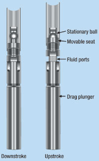
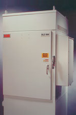
Traveling valve prevents gas lock without tagging. Eagle Advanced Oil Field Technologies of St. George, Utah, designed and manufactures its patented Solution Valve (SV), a traveling valve for incorporation within downhole rod pumps. The valve is positioned on the bottom of the plunger, with the usual traveling valve relocated at the top. Within the SV, the ball is centered and stationary, while the seat moves up and down in accordance with resistance imposed by its short drag plunger, Fig. 4. Consequently, the valve opens and closes upon initiation of down and up strokes, respectively. There is no mechanical impacting from below to force the ball off its seat, nor is it necessary to tag the plunger at the bottom of the stroke. Cross-sectional flow area through the valve’s ported seal stem offers minimal flow resistance. Functioning as a "mini-compressor," the SV displaces free gas, as well as oil, water or foam on each stroke. Benefits include: 1) continuous fluid loading throughout each upstroke; 2) by not having to tag bottom, rod-cut tubing, rod parts, and failures of valve rods and valve-rod guides are minimized; 3) gas locking is eliminated, both below the SV and between SV and the upper traveling valve; and 4) smooth, consistent, steady-state loading / unloading eliminates buildup and sudden release of high-pressure gas pockets below the plunger, thus preventing pump failures from violent impacting of balls against seats and cages. Further, more efficient loading / unloading of the assembly enables pump-off controllers and timers to reduce unit run time; gaseous fluids can be produced below a packer; and problems due to delayed ball seating or floating in horizontal / deviated holes or with heavy, viscous oils are eliminated. The SV is offered in a wide range of API metallurgies and sizes. Artificial-lift controllers. A new line of ALC 600 standard artificial-lift controllers for rod pumps, PCPs and ESP pumps from ABB, New Berlin, Wisconsin, features a new generation of power electronics and variable-speed drive (VSD) technology. The hardware, standardized in cabinetry for easy installation and use on wells in conditions found around the world, is built in combination with industry-specific ABB software solutions that optimize production while reducing maintenance and energy costs. Precise speed regulation of the motor in rod pump, ESP and PCP applications ensures both maximum inflow from the well and optimal pumping speed. Some applications have resulted in volume production increases of over 40%. VSDs are also claimed to reduce both downtime and energy costs.
The Rod Pump Controller combines the function of a VSD and a pump-off controller in one unit. Built for arctic, desert or tropical conditions in tamper-proof, heavy-gauge, powder-coated steel enclosures that meet oil industry requirements, Fig. 5, the electronics are housed in a separate NEMA 4 compartment; and the heat sink, optional filter and transformer are located in a ventilated, dust-protected NEMA 3R section. The dual-inverter (active front end) model ranges from 20 to 120 hp. The controller features a new generation of power electronics and VSD technology. Hardware is built in combination with ABB software designed to optimize production, while reducing maintenance and energy costs. The new product features patent-pending, advanced Fluid-Level Control and Rod-Saver software. The active front-end design mitigates harmonics and produces a near-unity power factor, while accurately controlling rod speed. A built-in dynacard capability allows the operator to access critical well information from either a built-in touch-screen color LCD display, a portable PC, or via a SCADA system.
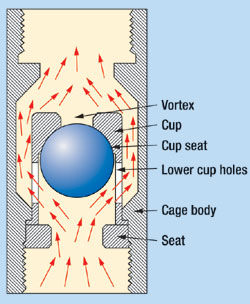
The new line includes pole-mounted units for PCPs. An easy see-through window on the cavity-door construction allows field personnel to check drive settings at a glance, Fig. 6. Optional dual-door construction. Standard enclosures for the ALC 600 artificial lift controllers are built from heavy-gauge, powder-coated steel, and all single doors feature three-point locking handles, dust-sealing gaskets, and they can be padlocked for security. Options include a single-door-and-cavity construction, or dual-door construction. Improved ball / seat / cage life. The life of a downhole pump is the fluid seals – the barrel to plunger seal – and valves (the ball and seat, and cages). There are several choices of ball / seat materials – stainless, cobalt alloy, tungsten carbide, nickel carbide and different types of ceramics. There are also many styles of cages, including plain steel, hard-lined, cobalt-insert and rubber-lined. In the past, there were design compromises, e.g., a harder ball / seat with less cage life, or a harder cage with less ball / seat life. In standard cage designs, when the valve opens, fluid flows through the cage, around the ball and out the top of the cage, and the ball is agitated in the turbulent fluid path. This spinning and chattering is what "beats out" the cage. Even a rubber-lined cage does not control the ball movement; it simply softens the impact. With the new Cup Cage from Skillman Pump Co., Mount Vernon, Texas, the operator can choose any ball / seat to match well conditions and the new cage will protect it. The unique thing about the new cage is that the ball seats on the seat when closed, and seats in the cup when open, Fig. 7. There is no movement or spinning of the ball when fluid passes through the cage.
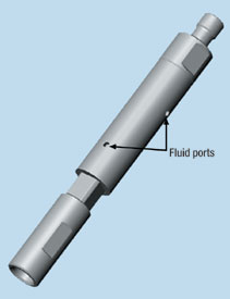
As pressure below the ball becomes greater than pressure above it, the valve opens. Fluid pushes the ball to the top of the cup. As the ball rises, fluid holes on the lower sides of the cup divert fluid to the inside of the cage body, but outside the cup. The inside of the top of the cup is milled to exactly fit the ball, with a hole exposing the top of the ball. As fluid goes around the outside of the cup and back over the top of the cup, a vortex or low-pressure area is created at the hole, which holds the ball, keeping it from moving while fluid passes through the cage. Besides protecting the valve, the new cage has more fluid flow area than standard cages. Without need for ball guides inside the cage, it uses the guide area for fluid flow. By design, all openings and orifices are based on the ID of the seat, to allow unrestricted fluid flow. All sizes are available for insert and tubing pumps, including Skillman’s retrievable vertical discharge standing valve, and top-open cage for tubing pumps. Stress and torque reduction. The patented Stress and Torque Reducing Tool (STR Tool) was invented by John Agee of Big Lake, Texas, in 1990, and tested extensively in deep West Texas oil and gas wells, Fig. 8. Harbison-Fischer, Crowley, Texas, was recently selected by the inventor as the exclusive manufacturer and distributor.
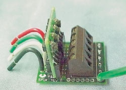
The tool is installed just above the sucker rod pump and dampens shock loads through the hydraulic dampening action of fluid moving in and out of the tool in wells that either tag the pump or experience fluid and/or gas pound. It is a hydraulic shock dampener that works on the same principle as a shock absorber on an automobile. Well fluids are forced through orifices on the pump upstroke and downstroke. This transfers shock loads to the fluid moving through the tool. A small part of the stroke, 1-1/4 in., is given up to achieve this benefit. The tool is made from 316 stainless steel and is clutched so that other downhole tools can be operated, or the sucker-rod pump can be rotated as needed during unseating. Pump barrel / plunger wear treatment. Harbison-Fischer has recently announced two long-wearing, robust surface treatments for sucker rod pump barrels and plungers. Both surface treatments have been field tested for three years in abrasive and low-lubricity conditions with good results. The new HTC 75+ barrel inside treatment is a proprietary treatment of the inside surface of chrome molybdenum steel. The new process is similar to carbonitriding in that it is a treatment of the surface and not a coating. Thus it cannot flake off like chrome plating. It is harder and thicker than – and has been designed to be a substitute for – chrome plating. As a comparison, the following data show: 1) Chrome plating: HRC 67 minimum, 0.003-in. thickness per side; 2) HTC 75+ treatment: HRC 75 minimum, 0.005-in. depth per side. For increased exterior corrosion resistance and ductility, the core hardness and outside surface hardness of the treated barrel is relatively soft and ductile, with less than HRC 23 hardness. The new Tuffr Plus plunger coating is a sprayed-metal coating similar to existing sprayed-metal coatings, except that wear life has been extended significantly by addition of hard, abrasion-resistant carbide particles. The coating thickness is about 0.010-in. per side. The exact percentage and size of particles is optimized by industry standard lab wear testing and downhole field testing. The new sprayed-metal coating is metallurgically bonded to the base material during the spray-metal process so that it cannot flake off. It is available on all pin end, box end, grooved and monel pin plungers. Load cell protection. Automation & Electronics of Casper, Wyoming, offers its ZAP-Stix surge protection module for load cells, which provides enhanced lightning protection for load-cell input for rod-pump controllers, Fig. 9. The module comprises two components: a permanently installed terminal board, and an active protection module designed to be easily replaced when limits are exceeded.
Transient over-voltage protection protects both load cells and pump-off controller from surge damage by interrupting the circuit between National Electrical Code ground path and rod string. Coordination with POC load measurement and surge protection circuits is designed for low noise, yet high surge-withstand capability to avoid nuisance outages. Progressing Cavity Pumping Three PCP developments include a stuffing-box sealing system for harsh, abrasive environments; downhole pump drive heads for medium- and light-duty PCP applications; and new approaches to use of composite materials for pump rotors and stators.
Stuffing box sealing system. The new Ultra-Guard Sealing System from R&M Energy Systems, Houston, a unit of Robbins & Myers, Inc., successfully addresses environmental and maintenance problems caused by stuffing box leakage in the top drives of PCP artificial lift systems, Fig. 10. Designed and developed specifically for harsh, abrasive environments, including high pressures and speeds, the system utilizes a unique hydrodynamic principle to provide seal-to-shaft separation via a lubricant film, virtually eliminating seal and shaft wear while excluding abrasives. Dual independent seal chambers permit continued leak-free operation even if one of the rotary seals fails. Available in 1-1/4- and 1-1/2-in. polished rod sizes, the system is compatible with the entire line of Moyno Ultra-Drive drive heads and can easily be adapted to fit most other drive heads. As additional features and benefits, the system:
Further, the system has proven reliable in the presence of abrasives; it is suitable for high-pressure / high-speed combinations; and it is easily installed and maintained. Medium / light duty drive heads. R&M Energy Systems offers the new Moyno Ultra-Drive Model CD1 downhole pump drive head, Fig. 11. This electrically driven system offers rugged construction and numerous operational features that make the "C" series drive heads attractive for medium-duty PCP applications. The system features polished rod speeds ranging to 600 rpm and a 1,600-ft lb torque rating on its recoil braking system.
The low profile design of the unit simplifies field mounting and installation, and a removable sealing system permits flexibility and easy servicing. It can accommodate either 1-1/4 or 1-1/2-in. polished rods. Additional features and benefits include: 1) side lifting lugs and multiholed lifting bracket facilitate lifts; 2) single-point belt tensioning system; 3) a low profile for use with overhead irrigation systems; 4) its hinged belt guard allows unobstructed access; and 5) increased thrust bearing capability assures long service life. For light-duty PCP applications, R&M offers the Moyno Ultra-Drive Model AD1 drive head, designed for use with Moyno downhole PCPs in oil-well production and gas-well dewatering applications. This electrically driven drive head offers rugged construction and numerous operational features. It offers polished rod speeds ranging up to 600 rpm and a 460-ft lb torque rating on its recoil braking system. The hollow-shaft, lightweight, compact design of the AD1 unit simplifies field mounting and installation and can accommodate 1-1/4-in. polished rods. Additional features and benefits are the same as those listed for the Model CD1 drive head. Composite PCP elements. The newest technological advancement in the PCP industry has been use of composites in the manufacture of PCP elements. This patented technology is being developed by G-PEX, Tulsa, Oklahoma, with manufacturing in Pearland, Texas (Houston). In this early development stage, the stator is made of a hard composite material and is placed in a steel tube jacket. The composite material offers similar wear characteristics to metal, but makes the stator the longer lasting element. The rotor is made of steel and coated with an even thickness of a soft and durable polyurethane. The urethane offers increased wear resistance and mechanical properties over conventional elastomers and, when placed on the rotor, offers the advantage of the wear element being located on the end of the sucker rod string rather than on the end of the tubing string. The composite PCP becomes a highly durable system that incorporates the emerging even-thickness-elastomer technology, which has been under development in conventional stators for years and has been proven to offer increased mechanical properties. The even thickness allows for more consistent thermal expansion and chemical swell within the pump, enhancing performance predictability in most applications. The method of processing the coated rotor allows for use of more advanced materials, which resolves many compatibility issues realized with conventional nitrile-based elastomers. With the elastomer placed on the rotor, the wear part is much-less time consuming to retrieve / replace, which will cut workover costs by more than 50%. The composite stator offers increased wear and corrosion resistance, allowing it to remain in the well longer. This PCP technology advancement is currently being thoroughly lab and field tested. The next development phase will be all-composite stators and rotors. Applications are being sought to help prove this emerging technology. Plunger Lift Two equipment / electronics innovations for plunger-lift operations include a two-piece plunger that cuts "drop time," and a new controller that incorporates the latest in ultra-low-power electronics technology. Two-piece plunger. Pacemaker Plunger, a division of MGM Well Service, Corpus Christi, Texas, has introduced a new plunger design in an effort to solve some of the problems that are inherent in current plunger-lift technology. Conventional plungers require a "shut-in" period to allow the plunger to drop, and to build enough well pressure in the annulus to drive plunger and fluid to surface.
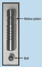
The Pacemaker two-piece plunger, Fig. 12, is designed to trip to bottom while the well is producing gas at considerable rate. In some wells, the plunger falls to the bottom while the well is producing at 1,000 Mcfd or more. Both pieces of the plunger have considerable bypass area, allowing the well to produce around the bottom piece (the ball) and through the top piece (the piston). They join at the bottom and are held together by the flow from the zones below as it pushes the plunger (now one unit) and its fluid load to surface. The surfacing plunger strikes a shifting rod and a gas-powered catch cylinder, which separates the two pieces and holds the piston for a short time. The ball falls back to bottom. When released, the piston arrives at the bottom of the well and joins with the ball, beginning the process again. The plunger can trip to bottom and back at speeds of 1,000 ft/min., or faster, while the well is flowing gas. The high round trip speed allows the plunger to lift smaller amounts of fluid with each trip so it can lift more fluid per day with less average BHP than conventional systems. Another advantage is that the system performs well without using the casing / tubing annular volume for pressure storage. The new plunger relies more on volume than trapped pressure to trip the plunger to surface. It works in 1-7/8-in. slim hole or wells with a packer and no communication with the annulus. On-site compressors usually adapt easily to the new plunger because the "shut-in" time of only seconds has almost no effect on compressor suction pressure. Plunger-lift controller. eProduction Solutions, Houston, offers a revolutionary design for plunger-lift system control and optimization that incorporates the latest in ultra-low-power electronics technology and sophisticated RTU functionality, to provide a complete plunger-lift controller system. Four control states allow configurable optimization using both time- and pressure-based optimization. Incorporated to provide user resources are:
The controller is capable of polling local "intelligent" peripherals, using Modbus communication protocol, to retrieve and store data. For example, the controller can poll a local electronic flow measurement RTU system and store gas-flow volume / rate information using the multi-channel datalogger. By centralizing the information from all local intelligent devices, upfront cost for optimization is decreased. Up to four local devices can be polled. Modular auxiliary I/O is available to expand the base controller to provide interface for casing / tubing pressure sensors and other peripherals. Logging and trending of this information can be achieved through use of the multi-channel datalogger. All information is available remotely through optimization software available from eProduction. Gas Lift In one gas-lift-related development, a new surface pump can handle liquids with entrained gas to lower back pressure on the tubing string and improve artificially lifted production.
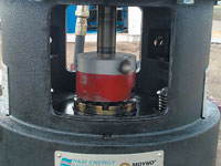
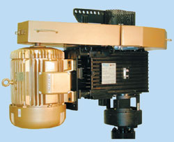
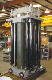
Multiphase pump lowers surface back pressure. Weatherford Artificial Lift Systems, Houston, has used its new RamPump to increase production by more than 700 bpd on Nexen Petroleum’s Eugene Island Block 257 D platform, and produce a gas surplus from wells that previously had to borrow gas for artificial lift. The hydraulically operated, plunger-style, multiphase pump, Fig. 13, and has been operating continuously for more than a year, in parallel with a gas-lift compressor, to lower the back pressure of four wells producing to the platform. Being able to lower the wellhead pressure by multiphase boosting at surface can enhance the application of artificial lift systems. Prior to pump installation, the well produced into a platform separation system operating at 230 psi – the pressure needed to move the liquids 1.5 mi downstream to Platform C for final separation. Evaluation indicated increased production could be obtained by lowering the pressure to 50 psi. The pump was installed in March 2001. Pressure was lowered to 45 – 55 psi, and the pump began moving the liquids along with any entrained gas to Platform C. Free gas from the platform separator was diverted to the compressor where it was recycled for gas lifting the wells. Well productivity has been sustained, the pump has been mechanically reliable, and the operator is evaluating other properties that may capitalize on this method. Additional installations are planned, with units of varying capacity – from 10,000 to 150,000 bpd equivalent – and functionality, at discharge pressures as high as 1,250 psi. Special models can increase this discharge capability to well over 3,000 psi. The ability of the pump to manage the full wellstream across a broad pressure range has expanded its role to include well kick off and stimulation applications.
|
||||||||||||||||||||||||||||||||||||||||||||||||


- What's new in production (February 2024)
- U.S. operators reduce activity as crude prices plunge (February 2024)
- U.S. producing gas wells increase despite low prices (February 2024)
- U.S. oil and natural gas production hits record highs (February 2024)
- Dallas Fed: E&P activity essentially unchanged; optimism wanes as uncertainty jumps (January 2024)
- Enhancing preparedness: The critical role of well control system surveys (December 2023)

