Reliable, low cost vapor recovery system saves money while helping the environment
Reliable, low cost vapor recovery system saves money while helping the environmentTroy Palmer, Devon Energy Corp.,
Bill Webb,* Bill Webb, Inc., and Dale Redman,** Hy-Bon Engineering Co., Inc. Bottom line. Since 1994, Devon Energy Corp. has employed the Vapor Jet system to capture hydrocarbon vapors from oil and water storage tanks in a West Texas waterflood operation. The system has proven to be a reliable, flexible, cost effective alternative for capturing hydrocarbon vapors to increase gas sales, while reducing hydrocarbon emissions. Through 1999, more than 55 MMcf of gas vapors have been recovered with operating expenses of less than $ 0.40 per Mcf. Prior problems. Historically, hydrocarbon vapor recovery from many oilfield production facilities’ oil and water storage tanks was considered uneconomical because of relatively low vapor volumes and low gas prices. In addition, compressor-based, vapor recovery systems could involve significant capital investment and often required excessive maintenance, which contributed to high operating costs. Changing conditions and improper monitoring or operation of the units led to high maintenance costs and related downtime. Too many times, vapor recovery systems were shut down to avoid ongoing high expense, especially in times of low oil prices. Fullerton field waterflood central tank battery. Kerr-McGee Corp. designed and constructed the Fullerton Unit central tank battery facility in Fullerton field, Andrews County, Texas, late in 1994. The property in this case study and the field operations personnel responsible for its construction and operation were merged into Devon Energy Corp. in 1996. The facility was equipped with the pumping and production equipment necessary to initiate and sustain waterflood operations. It also was designed to accommodate increased production from a planned, multi-year infill drilling program. When designing the central tank battery, Kerr-McGee wanted a vapor recovery system that would:
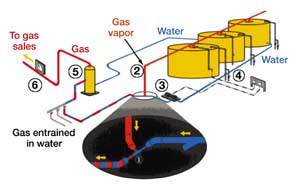
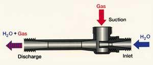
They selected the patented Vapor Jet vapor recovery system, but wanted it modified from its normal configuration. Vapor recovery system. The Vapor Jet system is ideal for facilities where the vapor volumes are on the low end of the range of compressor-based vapor recovery systems – sometimes referred to as "environmental units." The system uses produced water as the operating medium for a jet pump, Fig. 1. A single-stage, high-head centrifugal pump, driven by an electrical motor, is used to pressurize the produced water to 200 – 225 psig. The produced water enters the jet pump travelling through a nozzle, which converts it to a high-velocity stream as it enters the suction chamber, Fig. 2.
Tank vapors, at near-atmospheric pressure, are piped from the tanks to the suction chamber of the jet pump. The high-velocity water stream, which has created a vacuum in the suction chamber, entrains the vapors. The water stream, with entrained vapors, travels to the diffuser section of the jet pump where the kinetic energy of the high velocity stream is converted to potential energy, resulting in a pressure that is greater than the suction chamber pressure, but significantly less than the jet pump entry pressure. The discharge from the jet pump is piped to the low pressure separation system of the production facility (must be less than 40 psig for the jet pump to function with the 225-psig inlet pressure). Vapors are separated and sold with other lease gas from the low-pressure separation system. The produced water used is separated and returned to the water tanks. In Kerr McGee’s installation, the operating medium for the jet pump is fresh water circulated in a closed system, which contains its own separator and water storage tank. The water is continuously circulated, with only the gas vapors exiting to gas sales. There are three major system components: pressure controller, centrifugal pump and motor, and jet pump. The pressure controller is the same type used with compressor-based vapor recovery systems. When pressure in the vapor space of the tanks reaches a predetermined set point, the pressure controller activates the system by turning on the centrifugal pump. When sufficient vapor volumes have been removed to reduce the pressure to a predetermined point, the pressure controller deactivates the system by turning off the centrifugal pump. The single-stage centrifugal pump and motor are the only components having moving parts, and are very durable, even when pumping produced water. Although lacking in efficiency, the single-stage centrifugal pump’s ability to develop a high head with the produced water – both reliably and with very little maintenance – more than compensates for its lower efficiency, when considering the overall cost of vapor recovery. Jet pump sizing is based on anticipated vapor volumes, and the size of the jet pump determines the rate of water to be pumped. Although jet pumps will work at different pressures, the vapor jet systems utilize an inlet pressure of 200 – 225 psig. Discharge pressure must be less than 40 psig to create the required vacuum in the suction chamber. The system can be installed for about 75 – 80% of the cost for compressor-based vapor recovery units in sour service and even less for sweet service. The three sizes of jet pumps currently in use, which allow recovery of up to 77 Mcfd, utilize the same size single-stage centrifugal pump. Impeller diameter and size of the motor and motor starter will vary between applications. This flexibility allows the output of a particular size of installation to be increased with very little additional capital expenditures. Virtually, the only operating expense is the cost of the electricity to drive the centrifugal pump. Devon central tank battery installation. At start-up of the facility, 15 wells produced about 400 bopd, 300 bwpd and 150 Mcfd total gas. With this production volume and facility operating conditions, tank vapor volumes were estimated at less than 20 Mcfd, but would be increasing as planned infill drilling proceeded. The Vapor Jet system installed had a single-stage centrifugal pump and motor capable of supplying fresh water to a 2-1/2-in. jet pump at 142-gpm and 200-psig. Under these conditions, the system was capable of recovering a maximum of 77 Mcfd of tank vapors when operating continuously. In 1997, lease production peaked at 1,500 bopd, 1,000 bwpd and 230 Mcfd. At this peak production rate, hydrocarbon vapors exceeded the capacity of the 2-1/2-in. jet pump. A second pump and motor, with a 2-in. jet pump to operate in tandem with the first, was installed to recover the excess vapor volumes. The tandem jet pump, at 200-psig and 82-gpm, would recover up to 45 Mcfd of additional tank vapors. When vapor volumes began to decline, the tandem pumps operated in a "lead – lag" mode until vapor volumes were well within the capacity of the first larger jet pump. This freed the second pump for use in a stand-by capacity or for use elsewhere. Currently, lease production is 820 bopd, 850 bwpd and 160 Mcfd from 27 wells, and tank vapor volumes are well within the capacity of the first 2-1/2-in. jet pump. From initial installation through 1999, some 55 MMcf of hydrocarbon tank vapors have been captured and sold. Revenue from this captured gas has been about $91,000. Unit capital cost to date equates to only $0.45/Mcf of captured gas. With a much longer anticipated life, ultimate unit capital cost will be significantly lower. The equipment used is so durable that another 10 – 15 years of life is expected. This would lower the capital cost to the $0.20 – 0.25/Mcf range, providing vapor volumes equate to the first five years of recovery. Over the five-year life of the system, the only maintenance required has been an occasional pump packing, so downtime has been virtually nil. The only operating cost associated with the vapor recovery system has been the cost of electricity to drive the centrifugal pumps – a cost less than $0.40/Mcf of captured gas.
|
|||||||||||||||||
- Applying ultra-deep LWD resistivity technology successfully in a SAGD operation (May 2019)
- Adoption of wireless intelligent completions advances (May 2019)
- Majors double down as takeaway crunch eases (April 2019)
- What’s new in well logging and formation evaluation (April 2019)
- Qualification of a 20,000-psi subsea BOP: A collaborative approach (February 2019)
- ConocoPhillips’ Greg Leveille sees rapid trajectory of technical advancement continuing (February 2019)

