Dual-gradient drilling nearly ready for field test
DRILLING TECHNOLOGYDual-gradient drilling nearly ready for field testIndustry’s SubSea MudLift Drilling JIP is starting to assemble an integrated package of critically tested components for their first offshore testKenneth L. Smith, Conoco, Inc., Project Manager for the SubSea MudLift Drilling JIP; Curtis E. Weddle, III, Cherokee Offshore Engineering, Team leader for JIP well control procedures; Charles P. Peterman, Director of Research, Hydril Co.; and Robert E. Snyder, Editor, World Oil
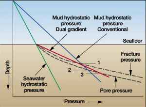
Following a major change in design of the subsea mudlift pumping system in late 1999, the project is now completing its third and final phase, and the proven components will be assembled starting this fall for a field test on a Texaco-operated, Gulf of Mexico well. The following discussion reviews the concept of dual-gradient drilling (DGD) and how it can provide a larger-diameter, less-costly casing program for high-productivity wells in very deep water. The major components of the mudlift system developed by the JIP are then described in an overview of how the system works. And important new well control methods developed by the JIP to make application of the new system acceptable are summarized. The revised JIP schedule combining the original Phases III and IV into the present Phase III – which is now rapidly nearing completion – is discussed. And preparations for the early-2001, Gulf of Mexico field test to be completed by mid-year are noted. Dual-Gradient Drilling Advantages Two previous World Oil articles presented the DGD concept, along with progress of the associated JIP. 1,2 To understand "dual-gradient drilling," one must contrast it to "single-gradient-drilling" technology. Today, when mud is pumped down a drillstring to the bit and back up to the rig through a riser, the open formation sees a hydrostatic pressure equal to the entire mud column from bit to surface. For example, when the bit penetrates the first foot below the mudline, that foot of formation is exposed to full mud-column pressure, whereas its pore pressure is only equal to a column of seawater. In shallow water, this is not a problem. However, in deeper water, very shallow zones cannot be drilled with a full mud column, and many more casing strings are needed in the upper-hole intervals to protect the well from the pressure burden of the mud column in the drilling riser. The basic concept of dual-gradient drilling is to create a situation in which the well perceives that only seawater exists above the mudline. In doing so, the fluid columns imposed on the well reflect those which created the pore pressure and fracture strength to begin with, i.e., sediments, overlain by seawater. When this is done, the formation below the mudline reacts as though the rig is sitting on the seafloor, and the well is designed as if it were a shallow-water well. This concept is illustrated by the schematic drawing in Fig. 1, which shows the mud hydrostatic pressure line representing a longer column of lighter weight mud intersecting the flatter (higher gradient) pore / fracture pressure lines at a steep angle. The vertical depth interval over which this lighter mud gradient is able to remain within the pore pressure and fracture gradient lines is fairly short, and casing must be set to prevent lost circulation or well influxes. Conversely, with mudlift, starting at the seafloor with a slope closer to that of pore / frac pressure gradients, the dual-gradient line allows significantly greater depth between casing points, as illustrated in Fig. 1.
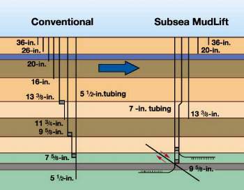
With this advantage, dual-gradient drilling gets to the desired TD with fewer, and larger-diameter, casing strings, as illustrated in Fig. 2. Here, conventional drilling requires a final string of 7-in. casing. In the dual-gradient well, 9-5/8-in. casing can be run to the same, or greater, depth, resulting in fewer casing points. This will reduce the number of days required to drill the well and final cost, e.g., each casing point installation could cost the operator $1.5 to 2 million. And it allows larger pipe at TD and greater production potential from wells. Larger wellbores are also needed to perform modern multilateral completions that can more effectively drain reservoirs with fewer high-cost wells. With fewer wells and less weight from well risers, more versatility and opportunities for further cost reduction will be available for deepwater production facilities.
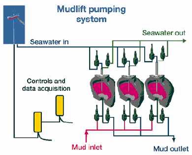
How It Works The technology required to create a dual-gradient situation consists first of a pump at the seafloor which collects the mud at the seabed and returns it to the rig. This MudLift Pump mechanically isolates the mud return line from the wellbore annulus and maintains a pressure on that well annulus equal to the seawater’s hydrostatic pressure. This creates the dual seawater / mud pressure gradient on the annulus side of the well. The consequence of pumping mud returns back from the mudline is that a pressure imbalance then exists between the wellbore annulus and the drill pipe, which extends all the way back to the rig and is filled with mud. Managing this U-tube is the challenge behind all of the drilling operations and well-control procedures. The U-tube can be mechanically arrested by using a drillstring valve (DSV) inside the drillstring; this is discussed later. The concept the JIP has developed modifies the conventional system by locating a positive-displacement pump within a module located on the base of the riser and pumping the returning mud back to the rig through a separate pipe on the outside of the riser. The annulus within the riser around the drill pipe is filled with seawater. SubSea MudLift Pump (SMLP). The principal component of the SubSea MudLift Module – which is located above the lower marine riser package – is the MudLift Pump, Fig. 3. In the version being manufactured for the upcoming field trial, this system will be a single, triplex pumping system comprising three, 80-gal diaphragm pumps, Fig. 4, and associated mud valves; each of these three pumps will discharge 2 bbl/stroke into the 5 to 6-in.-ID mud riser line. The mud is displaced from the pump by pressurized seawater pumped from the rig down a separate 5 to 6-in.-ID line on the riser.
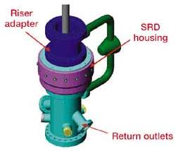
The large pump chambers help ensure that the pumps do not mechanically reduce the cuttings. This is helpful for formation evaluation and pore pressure prediction, and will avoid the fine-solids buildup that could be experienced with a more aggressive pump design. This latter point will keep mud dilution costs and environmental impact to a minimum. As a key point, it is seen that when the pump’s mud valves open to discharge the seawater power fluid to the sea and allow mud entry from the drill pipe-casing annulus, the mud enters the pump cavity on the inlet side of the diaphragm essentially at hydrostatic pressure of seawater at seafloor level. This ensures that mud within the drill pipe at seafloor level is also at seawater hydrostatic pressure – the basic premise of dual-gradient drilling. Other system components. To support the mudlift pump, the JIP has developed three other key system components. Within the riser, the SubSea Rotating Diverter (SRD) utilizes a rubber element around the drill pipe that rotates with the pipe, but allows vertical movement and sealing of pipe and tool joints, Fig. 5. This element – employing rotating seals to maintain an oil bath for the bearings to facilitate rotation – diverts mud from the annulus into the pump suction line. The SRD sealing element is pulled with the BHA and bit for inspection / maintenance.
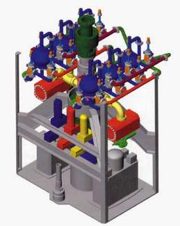
Between the diverter and the pump suction, the JIP-developed Solids Processing Unit operates to ingest large pieces of formation – particularly slugs of gumbo, float equipment, cement, etc. – and mechanically reduce them to less than 1-1/2-in. particles. Any cuttings smaller than 1-1/2 in. pass through without damage. A successful field test of the "sizer" has been recently completed and the system is being adapted to the subsea module. In the test, returns from an entire well offshore Louisiana were successfully processed. Fig. 6 depicts the SubSea MudLift Module with the MudLift Pump, Solids Processing Unit and SubSea Rotating Diverter, as run just above the lower marine riser package. The system shown differs from the field test system, in that two, independent triplex pump packages are shown. This will be typical of many larger commercial systems.
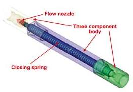
Drill String Valve (DSV). This is another unique piece of equipment developed by the JIP. When circulation is stopped, the U-tube pressure differential from drill pipe to well annulus can approach 5,000 psi, depending on water depth and mud density. Left unrestrained, this U-tube imbalance can equalize at initial rates up to 15 bbl/min. for 15 to 20 min., making kick detection more difficult. The DSV was developed to prevent this U-tube from occurring, making the well appear more "conventional" to the rig crew. It is also worth noting that operating and well-control procedures have been written to allow for a DSV failure; all operations can still be performed safely. The DSV is essentially a pressure-balanced drill pipe float with a very large spring, Fig. 7, run at or near the bit, and adjustable on the rig for opening pressure. In tests, the DSV had opening pressure repeatability within a few psi. In operation, the basic effect is to shut a valve in the drill pipe at any point below the seafloor when circulation stops, and open it when circulation starts. At drilling circulation rates, the DSV is held open with a very small pressure drop.
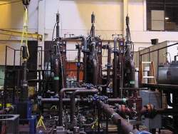
JIP Direction Change The system overviewed above is a modification of the system described in World Oil, August 1999. 2 At that time, the program called for the mudlift diaphragm pumps to be driven by four, 1,000-hp, subsea electric motors powering eight, hydraulic, variable-displacement pumps. These electric motors would have required large, high-voltage power cables and controls running through the moon pool down the riser. In late 1999, a design review was held with operations personnel from JIP participants, and there was considerable concern about the subsea electric motors and the massive, high-voltage power umbilicals necessary to run them. It was recognized that no reasonable amount of offshore testing would arrest these concerns, and the JIP elected to resurrect an old idea – seawater-driven subsea pumps. In the present concept, surface mud pumps would be used to pump seawater power fluid down a 5 to 6-in.-ID line under pressure to the SubSea MudLift pump. On newer, 5th generation rigs, this would be supplied by two of the four mud pumps. On smaller rigs, additional mud pumps would be added. This revised system eliminates the large power cables and subsea electro-hydraulic system. A small, ROV cable-sized control umbilical is added, along with the seawater power fluid and mud return pipes. Well Control Early on, the JIP recognized that retraining deepwater drilling personnel would be the largest of the challenges associated with MudLift Drilling. Thus, a tremendous effort has been placed in developing the operations and well-control procedures and evolving them into training modules. Over the last several months, these procedures have been improved and used to refine functional specs for the present system. MudLift pumps will return all drilling and formation fluids to surface, as well as circulate under changing inlet pressures and at variable circulating rates. All conventional well-control procedures can be accomplished with dual-gradient drilling, when newly developed well-control methods for the system are used. The team has sought to make DGD as safe or safer than conventional, deepwater drilling. In all of the various well-control procedures developed for DGD (and well completion through casing running) an active or potential U-tube is managed. This U-tube is the primary element of change compared to conventional well control. Dual, independent methods of pressure verification are provided in the new procedures, along with contingency plans for various potential failures. All the procedures have had at least one HAZOP process evaluation. All conventional kick detection measures are available in the procedures. Some indicators – like changes in return flow from the well, gas unit changes and cuttings or shale cavings – are improved as signs of increasing pore pressure. Bottoms-up time is significantly improved compared to conventional drilling. And "time drilling," so as not to out-drill pore pressure indicators, will be reduced (and may be eliminated) when using the new system. Kick prevention measures unique to DGD are part of the new system development. Good trip procedures are one of the best conventional means to reduce the incidence of kicks. DGD methods have been developed to keep the hole below the mudline full of mud and the riser above the mudline filled with seawater, as the capacity and/or displacement of the drillstring is removed from, or added to, the well. Bottomhole pressure is maintained above formation pressure and is nearly constant during trips. Conventional tools such as circulating trip tanks are still used in the new system. Annular friction pressure, long considered negligible in well control, is considered in the procedures. DGD system features are used to more safely manage changes in the annular friction pressure while drilling. Annular friction pressure while circulating increases effective pressure at the bit. So long as circulation continues, this added effective pressure may mask pore pressure increases encountered while drilling down a 90-ft + stand. When circulation is stopped for a connection, and BHP is reduced by an amount equal to the annular friction pressure, the increased pore pressure could create an inflow of formation fluid, sometimes referred to as the "kick that hides between static and circulating bottomhole pressure." Steps have been taken beyond developing methods for dual-gradient kick prevention, detection and management. For example, dual-gradient-drilled wells could require dual-gradient-drilled relief wells, and the team has developed approaches for dynamic kill of underground and surface blowouts. As part of the total system delivery, the JIP, in conjunction with Texas A&M University, is teaching comprehensive operations and well-control techniques to prepare drilling teams and JIP participants for the upcoming dual-gradient test. JIP Progress, Schedule Phase I of the SubSea MudLift Drilling JIP was created to investigate ways of managing effects of hydrostatic pressure at the wellhead. Twenty-two companies participated in the first phase. Drilling contractors and operators from Europe, North America and South America all realized the importance of the project. In the first phase, called Conceptual Engineering, more than $1 million was invested in technical / operational feasibility studies. The group agreed on the configuration of equipment needed and determined that both routine drilling operations and well control were feasible. It was also agreed that re-education of industry personnel would be a significant challenge. For drilling engineering and operations personnel, dual-gradient drilling requires a complete mindset change. Phase II, with the objective of developing the critical components, began in April 1998, with four operators, four contractors and one manufacturer. This phase also began development of operational and well-control procedures, including an advanced simulator and training schools. The test loop, located at Hydril’s Houston facility, opened in February 1999 and has been in nearly continuous operation, providing working data on mud valves and 20-gal diaphragm pumps and the drillstring valve, Fig. 8. The particle sizer was developed in a test flow loop and has been proved on a test well.
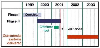
In November 1999, re-evaluation confirmed that the original concept of electric power cables and subsea electrohydraulic pumps was an unsatisfactory approach, so the concept of pressurized, seawater-driven diaphragm pumps was adopted. Phase II was completed on April 1, 2000, see revised schedule, Fig. 9.
Phase III, now well underway with eight remaining participants, has completed testing of the final configuration and its components. The JIP will take the proven components and, by mid-October, will start assembling an integrated package for factory acceptance by mid-December 2000. The JIP participants felt that actual field testing of the system had to be done before it could be considered commercially acceptable. Obviously, it is important to test the equipment in an actual drilling environment but – not so obviously – the drilling and well-control procedures can only be tested in a deepwater environment where the U-tube can be experienced. So, in mid-February 2001, the system will be mobilized to Diamond Offshore’s Ocean New Era and installed. The rig will move onto a Texaco-operated location in the Gulf of Mexico in 1,150-ft water, and a well will be drilled. Most of the operations and well-control procedures will be tested. Following the field test, all lessons learned will be incorporated, and the SubSea MudLift Drilling system will be commercially available by early 2002. It is important to note that the only real differences between the system
being used in 1,150-ft water and one used in 10,000-ft water are the seawater power supplied to the SubSea
MudLift Drilling package and the lengths of the seawater and mud-return lines attached to the marine riser. It
is also important to note that the SMD system was originally designed for the latest and largest of the
deepwater rigs; however, it is being installed and tested on a 2nd-generation semi, proving that the system is
not only very capable, it is very adaptable. And it is compact, weighing between 100,000 and 175,000 lb,
depending on the desired configuration. Literature Cited
|