00-01_new-jellison.html (Jan-2000)
New drill pipe size improves ERD and deepwater drillingPresently available 5-1/2-in. drill pipe may not offer critical hydraulic performance needed for deep wells in deep water, and 6-5/8-in. pipe has mechanical / handling limitations. One field-tested solution is an intermediate-size productMichael J. Jellison, Grant Prideco; and Dr. Mike Payne, ARCO Technology and Operations Services
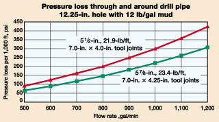
Realizing the full potential of 5-7/8 in. required development of a high-performance tool joint connection. The eXtreme Torque (XT) connection design, optimized for 5-7/8-in. drill pipe, provides exceptional torsional strength combined with a streamline configuration. The XT57 tool joint OD of 7 in. permits fishing of the connection with an overshot inside 9-5/8-in. casing or 8-1/2-in. openhole sections. This article discusses the engineering philosophy behind 5-7/8-in. XR drill pipe, and design challenges associated with development of the product, and it reviews features and capabilities of the new connection. An upcoming project that will use 5-7/8 in. will also be discussed. The project, operated by ARCO China Inc. in the South China Sea, is scheduled to begin in early 2000. Limitations Of 5-1/2 And 6-5/8-In. Drill Pipe Initial engineering work on ERD wells focused heavily on drillstring torque and drag issues. As ERD wells became more common and the horizontal displacement, or reach, of these wells increased, it became apparent that hydraulic performance of the drillstring represented a more restrictive limitation than torque and drag concerns. The 5-7/8-in. drill pipe was initially targeted at ERD well applications, which typically require long, 9-5/8-in. and larger-diameter, intermediate casing strings to reach their total depth objectives. Efficient drilling of the large-diameter (12-1/4-in. and larger) hole sections required for these strings requires a drillstring design that minimizes pressure losses through the pipe. As development work on the 5-7/8-in. XR progressed and drilling engineers were made aware of the project, interest in its use in deepwater applications was also generated. Deepwater wells drilled to true vertical depths approaching 20,000 ft and deeper are becoming more common.1 Many of these wells encounter sections with reduced margins between pore pressure and fracture gradients. As a result, they often require several intermediate casing points and long, 9-5/8-in. (or larger) intermediate casing strings. Just as in ERD wells, improved hydraulic performance of the drillstring can enhance drilling efficiency in deepwater applications. Substantial ERD and deepwater projects are generally drilled with 5-1/2-in. drill pipe, or a combination string of 6-5/8 in. and 5-1/2 in. Use of a full string of 5-1/2 in. introduces hydraulic limitations in long 12-1/4-in. (and larger) hole sections. And with 5-1/2 in., pressure losses through the drillstring are too great to efficiently remove cuttings from the well, resulting in slower penetration rates, diminished control over well trajectory and more tendency for drill pipe sticking Hydraulic pressure losses are minimized with 6-5/8-in. drill pipe, but it is an "over-design" solution in most cases. The 6-5/8 in. is difficult to handle, requires excessive physical space on the rig, can limit setback capacity and generally requires significant rig-handling equipment modifications. In addition, it cannot be used to drill inside 9-5/8-in. casing and 8-1/2-in. openhole sections. Consequently, once 9-5/8-in. casing is set, the 6-5/8-in. drill pipe simply adds to the rig setback weight and occupies valuable rig space. This is a major disadvantage on offshore projects, where rig space and setback capacity are at a premium. Due to the shortcomings of 5-1/2 and 6-5/8-in. drill pipe, an intermediate size is required. Based on engineering analysis and discussions with potential end users, 5-7/8 in. was determined to be an optimum size. Hydraulic Performance Fig. 1 shows a hydraulic performance comparison of 5-7/8-in., 23.4-lb/ft and 5-1/2-in., 21.9-lb/ft (most common 5-1/2-in. product for ERD applications) drill pipe. The graph shows the pressure loss in psi/1,000 ft while drilling inside 12-1/4-in. hole with 12-ppg mud. The benefit of the new drill pipe size is clearly illustrated in this comparison.
The 5-7/8-in., 23.4-lb/ft pipe provides 16% more ID flow area than 5-1/2-in., 21.9-lb/ft pipe. And pressure losses are reduced by about 28% with the 5-7/8-in. XR. Improved hydraulic efficiency of the 5-7/8-in. XR pipe permits higher achievable flowrates, resulting in better hole cleaning and faster penetration. In addition, drill pipe sticking tendencies are reduced due to better cuttings removal, and directional control of the well path is improved. Working pressure requirements for the mud circulating system are also reduced. Design Requirements After determining optimum size for the drill pipe, engineering design parameters or project goals were established as follows: 2
Each of the design goals listed above, with exception of the elevator capacity requirement, were met or exceeded with the final product configuration, Fig. 2. The elevator capacity requirement was nearly met. To maintain other highly desirable features of the final product, this requirement was adjusted downward slightly. The elevator shoulder capacity requirement is discussed in more detail below. Table 1 lists design specs for the 5-7/8-in., 23.4-lb/ft, S-135 and V-150, XT57 drill pipe.
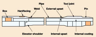
Several of the engineering design considerations warrant further discussion. Elevator shoulder capacity. Geometric constraints imposed with a 5-7/8-in. pipe body OD and a 7-in. tool joint OD limit area of the 18° box or elevator shoulder on the tool joints. The drill pipe was designed with a very slight external upset. By minimizing size of this upset, the elevator shoulder area is maximized. The decision was made to use an IEU (internal-external upset) configuration, as opposed to an IU (internal upset, only) for several reasons. Use of a slight external upset increases the weld line area, resulting in a stronger weld line; and it enhances manufacturing operations by simplifying weld line cleanup and dimensional control of the finished upset. In addition, with a +1% OD tolerance, the 5-7/8-in. tubes could have an actual diameter of up to 5.934 in. An IU configuration could result in a finished upset OD that was smaller than the pipe body OD. This could complicate the manufacturing and final inspection process and hamper use of elevators on the rig. Discussions with elevator equipment manufacturers indicated that elevator wear can be held at acceptable levels, and elevator rated capacity will not be exceeded, with a maximum bearing stress of 100,000 psi between elevator face and box 18° shoulder. This results in a maximum elevator capacity of 902,000 lb, with an elevator bore of 6-1/8 in. and the 7-in. tool joint box OD. Although this was slightly below the original 1,000,000-lb elevator capacity requirement, attempts to increase this value would compromise the upset configuration or force the use of a larger tool joint OD. In addition, this elevator capacity: 1) exceeds the tension rating (new and premium class) for the 5-7/8-in., 23.4-lb/ft drill pipe with S-135 grade material, 2) is only slightly below the new class tension rating with V-150 material of 936,600 lb, and 3) exceeds the V-150 premium class tension rating. The elevator manufacturer should be consulted for elevator capacity ratings for specific applications. Collapse rating. Selecting the optimum wall thickness for the 5-7/8-in. XR was driven, in large part, by the collapse-rating requirement. The primary design requirement for the drill pipe was to maximize ID flow area and optimize hydraulic efficiency. To achieve this goal, it was necessary to select the minimum nominal wall thickness that provided acceptable structural and pressure integrity. In addition, use of a larger-than-required wall thickness would increase pipe weight / foot, reducing acceptable maximum string length before exceeding elevator capacity. Initial engineering studies indicated that a wall thickness in the range of 0.324 in. was sufficient to provide the torsional, tension and collapse strengths required for ERD and deepwater applications. The new pipe-collapse rating of 5-7/8-in., 0.324-in.-wall, S-135 pipe meets the design collapse requirement of 8,000 psi. It was recognized that the new pipe ratings were generally unimportant for drill pipe, since the first time the pipe passes through the rotary table it is considered premium class (used) pipe. The premium-class collapse rating of the 0.324-in.-wall pipe is only 4,700 psi. Increasing the material yield strength provides virtually no improvement in the collapse rating of the pipe in this D/t (outside diameter / wall thickness) range. New and premium collapse ratings for 5-7/8-in., 0.324-in.-wall, V-150 drill pipe are 8,200 psi and 4,700 psi, respectively. However, the current API equations for calculating collapse rating of premium-class drill pipe are conservative. Although the actual minimum wall thickness of new drill pipe ordered to API specs could be 87.5% of nominal wall thickness, the collapse rating of new pipe is based on 100% of the nominal wall thickness. The premium-class collapse rating is calculated using 80% of nominal wall. Consequently, the first time the pipe is used, wall thickness must be reduced by 20% to calculate the collapse rating, although the minimum wall thickness for premium-class pipe is only 7.5% (of nominal wall thickness) lower than permitted for new pipe. Many operators inspect used pipe to minimum-wall-thickness requirements greater than 80% of nominal thickness. Minimum remaining thickness requirements of 87.5% or 85% are commonly required for used drill pipe on critical projects. ISO and API standardization committees are currently working on revised collapse equations that will improve the ratings of casing, tubing and drill pipe. Based on the factors discussed above, a nominal wall thickness of 0.361 in. was selected for the 5-7/8-in. drill pipe. The collapse ratings for 5-7/8-in., 23.4-lb/ft (0.361-in. WT), S-135 pipe are 10,830 psi (new) and 6,200 psi (premium). This wall thickness balances the requirements for maximum hydraulic efficiency and appropriate structural integrity. Table 2 lists API collapse ratings with various minimum remaining- wall-thickness values from 80% to 100% of nominal wall thickness.
Tension and overpull capacity requirement. A fundamental requirement for a well-executed drill pipe design is that tensile strengths of the tool joint-to-upset weld, and the tool joint itself, must exceed pipe body tensile strength. Consequently, for a given OD and wall thickness, the tensile strength of a joint of drill pipe is strictly a function of the material yield strength. In addition, for a tension design requirement expressed in terms of acceptable string length, material strength is the essential controlling parameter, regardless of OD and wall thickness. The tension design requirement is met with the new pipe rating of the V-150 product. Again, new pipe ratings are generally not relevant to drillstring design analysis. At the time the tension design requirement was established, it was recognized that it would be difficult to achieve. Further, actual ERD and deepwater well conditions relax the tension requirements in real-world applications.In ERD wells, the drillstring can reach lengths that exceed 35,000 ft measured depth, yet the true vertical depth of the string will likely be significantly less than 20,000 ft. In both ERD and deepwater wells, mud weight will provide buoyancy that lowers the effective string weight. Buoyancy was not accounted for in the initial design requirement. Using the design requirement as a reference, listed here are the overpull capacities with 20,000 ft of 5-7/8-in., 23.4 lb/ft (actual weight = 26.83 lb/ft) hanging vertically in air (no buoyancy): 1) new V-150, 401,400 lb; 2) premium V-150, 204,000 lb; 3) new S-135, 307,600 lb; and 4) premium S-135, 129,900 lb. The XT Connection An advanced, high-performance tool joint design was required to achieve dimensional / performance objectives for the 5-7/8-in. XR. The eXtreme Torque (XT) is a second-generation, double-shoulder connection, Fig. 3. XT57 is a connection configuration optimized for the 5-7/8-in. pipe.
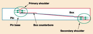
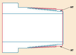
The connection design evolved from the design of the HIGH TORQUE (HT) connection. Fig. 4 depicts make-up characteristics of XT and HT. Both connections spin up freely from stab-in to hand-tight position. In the hand-tight position, the primary external shoulder makes contact. As the connection is made up from hand-tight to power-tight, the box counterbore compresses, the pin base elongates elastically, and the secondary torque stop engages. The secondary torque shoulder provides the increased torsional capacity, compared to a standard API rotary-shoulder connection.
The external (primary) shoulder is the pressure seal for the connection, just as on an API connection. Since the secondary shoulder functions solely as a torque stop and not a pressure seal, minor damage to the secondary shoulder can be tolerated without adversely affecting connection performance, provided there is no protruding metal that will impede contact between shoulder surfaces. Any protruding metal on the secondary shoulder must be removed with a file or abrasive paper. Use of thread protectors when the pipe is racked back in the derrick is neither required nor recommended. Fig. 5 shows a comparison of XT and HT. The thread taper of the XT connection was flattened to increase the secondary torque-stop area, resulting in increased torsional capacity. HT provides an approximate 40% improvement in working torque, compared to an API connection of the same OD and ID dimensions. XT provides about 30% more working torque capacity than HT, or an improvement in working torque of about 70%, compared to a standard API connection of the same dimensions.
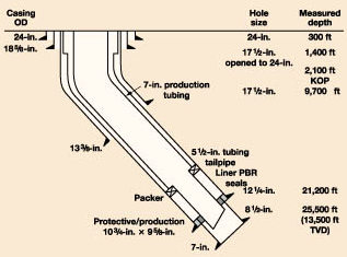
The shallow thread taper of the XT connection results in reduced clearance between pin nose and box face during stabbing. Consequently, use of a stabbing guide is required to prevent damage to the box face or shoulder that acts as the connection pressure seal. With the exception of the stabbing-guide requirement, XT handles and makes up like a standard API connection. The double-shoulder configuration permits streamlined configurations with reduced ODs and larger IDs, while still maintaining the desired torsional strength. XT can be refaced, and a portable refacing tool is also available to eliminate shipping costs to a machine shop for repair work and for use in remote areas where machine shops are not readily accessible. Drill Pipe Handling Only minor modifications are needed with regard to pipe handling equipment to use the 5-7/8-in. XR drill pipe. These considerations are discussed below. Elevators – The XT57 connection has a standard 18° elevator shoulder. The elevator bore must clear the 6-in. external upset on the pipe. A 6 1/8-in. bore provides adequate clearance around the upset. As discussed above, because of the limited elevator-shoulder contact area, the elevator capacity rating will be somewhat less than 500 t. Discussions with elevator manufacturers indicate that the elevator rating should be in the range of 430 to 450 t. Care should be taken to inspect the elevators for wear on a frequent basis. Due to the reduced contact area, bearing stresses may be higher than typical, compared to 5-1/2-in. drill pipe, and elevator wear will be higher than normal. Extra elevator inserts should be available to allow regular change out, when required. Blow-out preventers – Standard annular BOPs and shear rams are compatible with the 5-7/8-in. XR. Either variable-bore rams or inserts machined to fit the 5-7/8-in. pipe can be used for pipe ram BOPs. Special, fixed-size pipe rams have already been successfully designed and manufactured for the 5-7/8-in. XR. Top drive bell stabbing guide – This stabbing guide, located below the top drive, centers the box connection at the top of a drill pipe stand under the pin on the saver sub. Due to the reduced clearance between pin nose and box face on the XT57 connection, the centralizing device in the bell guide must have an effective ID of 7.5 in., or less, to ensure that the pin does not damage the box face when stabbing the saver sub into the top of a drill pipe stand. The centralizing device is generally a sleeve or a set of flippers. On one manufacturer’s top drive, the "standard" flippers used with 5-in. API drill pipe provide the correct centralization for the XT57 connection. Slips – A 7-in. slip body dressed with inserts to grip the 5-7/8-in. pipe body should be used. Finger board – The finger board spacing should be evaluated for each rig that will be used to drill with the 5-7/8-in. XR drill pipe. On the first 5-7/8-in. drill pipe job, no modifications were required. Stabbing guide – As discussed above, a stabbing guide should be used on the rig floor anytime an XT57 pin is stabbed in a box. This will ensure proper alignment and reduce stabbing damage. Mud bucket – A standard mud bucket can be used with the 5-7/8-in. XR drill pipe and XT57 connection. The mud-bucket bore must be sized to seal around the 5-7/8-in. pipe body. Iron Roughneck – Standard pipe handling equipment can be readily adapted to fit the 5-7/8-in. drill pipe. Accessories – The top drive saver sub, crossover subs and other accessories made-up into the drillstring must be threaded with the XT57 connection. During well planning, compatibility of drill pipe safety valves, darts, balls, etc. should be evaluated. Applications The first string of 5-7/8-in. XR drill pipe went to work for a major operator on a Gulf of Mexico project in July 1999. Two additional strings started jobs in October 1999. The second and third 5-7/8-in. drillstrings are being used on deepwater Gulf of Mexico projects operated by major oil companies. ARCO China Inc. purchased a string of 5-7/8-in. XR for its Yacheng ERD project in the South China Sea. Phase 2 of this project is slated to begin drilling in the first quarter of 2000. A typical casing program for Yacheng field is depicted in Fig. 6. The project will include two platforms, with ERD wells planned from both platforms. Wells are planned with horizontal departures up to 20,000 ft and measured depths to 25,500 ft – about 13,500-ft TVD.
The improved hydraulic performance of the 5-7/8-in. drill pipe, relative to 5-1/2-in., will be extremely beneficial in drilling the long, 12-1/4-in. hole sections to measured depths in excess of 21,000 ft. Although, the 5-7/8 in. is not required to drill the 17-1/2-in. hole section, it will also improve drilling efficiency in this interval. About 125,000 ft of 5-7/8-in. XR drill pipe has been manufactured. An additional 55,000 ft of 5-7/8-in. XR is being manufactured, or is on order. By early 2000, up to six strings of 5-7/8-in. XR drill pipe will be available for rental in regions throughout the world. LITERATURE CITED
The authors
Copyright © 2000 World
Oil |
||||||||||||||||||||||||||||||||||||||||||||||||||||||||||||||||||||||||||||||||||||||||||||||||||||||||||||||||||||||||||||||||||||||||||||||||||||||||||||||||||||||||||||||||||||||||||||||||||
 Michael
Jellison, Product manager, Drill Stem Products
Division, Grant Pride-co, graduated from Texas A&M University in 1980, with a BS in
mech-anical engineering. He joined Oil Technology Services, Inc. in 1982, where he
specialized in design of deep, high-pressure, complex wells, in addition to work on two
tubular design programs. In his present position, he directs product development, manages
drill stem business efforts and provides technical assistance to customers. He initiated the
effort to develop the 5 7/8-in. drill pipe for ERD and deep wells. Mr. Jellison has written
several technical papers on tubulars and premium connections. And he has conducted design
schools and seminars on these subjects.
Michael
Jellison, Product manager, Drill Stem Products
Division, Grant Pride-co, graduated from Texas A&M University in 1980, with a BS in
mech-anical engineering. He joined Oil Technology Services, Inc. in 1982, where he
specialized in design of deep, high-pressure, complex wells, in addition to work on two
tubular design programs. In his present position, he directs product development, manages
drill stem business efforts and provides technical assistance to customers. He initiated the
effort to develop the 5 7/8-in. drill pipe for ERD and deep wells. Mr. Jellison has written
several technical papers on tubulars and premium connections. And he has conducted design
schools and seminars on these subjects.  Dr.
M. L. (Mike) Payne is an advisor with ARCO
Exploration and Production Technology in Plano, Texas. He holds a BSME degree from Rice
University (1982), an MS degree in petroleum engineering from the University of Houston
(1984) and a PhD in mechanical engineering from Rice University (1992). Previously a
consultant, he has 18 year’s industry experience and has been with ARCO for 15 years in
positions of increasing responsibility in drilling operations / research. He was seconded to
BP to work on the Wytch Farm ERD project, and he is continuing work on ERD, HPHT drilling
and high-performance well construction. Dr. Payne has published numerous technical papers
for SPE, IADC, ASME and several trade journals. He is a registered professional engineer, a
member of the SPE Editorial Review Committee, Vice-Chairman of API Subcommittee 5 and
Covenor of ISO/TC67/ SC5/WG2. He served as an SPE Distinguished Lecturer during the 1995–’96
season on the subject of ERD.
Dr.
M. L. (Mike) Payne is an advisor with ARCO
Exploration and Production Technology in Plano, Texas. He holds a BSME degree from Rice
University (1982), an MS degree in petroleum engineering from the University of Houston
(1984) and a PhD in mechanical engineering from Rice University (1992). Previously a
consultant, he has 18 year’s industry experience and has been with ARCO for 15 years in
positions of increasing responsibility in drilling operations / research. He was seconded to
BP to work on the Wytch Farm ERD project, and he is continuing work on ERD, HPHT drilling
and high-performance well construction. Dr. Payne has published numerous technical papers
for SPE, IADC, ASME and several trade journals. He is a registered professional engineer, a
member of the SPE Editorial Review Committee, Vice-Chairman of API Subcommittee 5 and
Covenor of ISO/TC67/ SC5/WG2. He served as an SPE Distinguished Lecturer during the 1995–’96
season on the subject of ERD.- Applying ultra-deep LWD resistivity technology successfully in a SAGD operation (May 2019)
- Adoption of wireless intelligent completions advances (May 2019)
- Majors double down as takeaway crunch eases (April 2019)
- What’s new in well logging and formation evaluation (April 2019)
- Qualification of a 20,000-psi subsea BOP: A collaborative approach (February 2019)
- ConocoPhillips’ Greg Leveille sees rapid trajectory of technical advancement continuing (February 2019)

