Survey technology keeps pace with move to deeper waters
OPERATIONS REVIEWSurvey technology keeps pace with move to deeper watersOperators choose advanced sensors, other tools to comply with regulations, ensure pipelay precisionRichard Prothero, Racal NCS, Houston, Texas
Technology already is available to improve survey data quality. New depth sensors and other technologies can provide operators the precise data they need to plan and build deepwater pipelines. Use of these more advanced survey technologies, however, will dictate use of even more sophisticated data management and processing. Here too, the relevant technology and techniques are available. The application of new technology, however, is not only driven by operator need to overcome deep water’s technological and operational challenges. It also is driven by the need to satisfy regulatory requirements. In the process of planning, permiting, and building a deepwater line, the operator and survey and installation contractors have to work together, utilizing these new technologies as regulations and circumstances dictate. Introduction With cost increasing for installing permanent deepwater structures, using pipelines tied back to fewer producing platforms is the expected development scenario for the future. In the Gulf of Mexico, out to 650 ft, there are 3,638 active leases and 3,462 active platforms. In waters deeper than 650 ft, there are 3,996 active leases and 507 active platforms. The deepwater environment in the Gulf of Mexico is still developing.
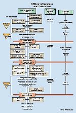
Reviewing steps involved in pipeline route and installation surveys helps highlight technologies already in use, and those available for the future. In the planning stage, the oil or gas operating company identifies regulatory requirements that have to be met for building an offshore pipeline. The Minerals Management Service (MMS), as the regulatory authority for the Gulf of Mexico OCS, requires operators to follow established procedures when applying for permission to develop a prospective offshore discovery. The process is outlined in Fig. 1. One of the key pieces of information an operator must have is a survey of the prospective area. The survey-related areas of permiting affecting pipeline installation include:
These regulatory instruments are designed to allow the MMS and the operator to make informed decisions about the environmental impact and safety of any proposed offshore development. From the hazard-survey contractor’s perspective, it is crucial to have access to information on existing structures, geophysical history and MMS regulatory requirements. With this information, the survey contractor is in a much better position to plan, execute and report the survey, and thus help the client (the operator) make an informed decision about a proposed route and survey method. Survey equipment The level of equipment sophistication depends on MMS requirements. A typical package for a pipeline route survey will include:
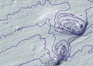
Modern technology now allows survey companies to utilize multi-beam echo sounders. These devices produce a corridor of depth ranges recorded along a single survey line, typically called a swathe. The result is an increase in depth data density, which facilitates creation of digital terrain models (DTMs). These DTMs provide the added design capability that enables three-dimensional pipeline modeling. As water depth increases, sensor-position accuracy decreases. These sensors are usually towed behind the survey ship. Once 650-ft waters have been reached, the distance behind the vessel at which the sensors must be towed increases to 2,000 ft. As this "layback" increases, consideration must be given to positioning the towed body with an ultra-short baseline (USBL) acoustic system mounted on a chase vessel. Measured against conventional towed-body arrangements, use of ROVs and autonomous underwater, vehicle-mounted sensors can trim survey acquisition and deployment time. Accurate positioning can be achieved by integrating USBL acoustics with attitude sensors, inertial navigation systems and doppler-velocity logs. The doppler-velocity logs provide relative measurements that reduce the instability of raw USBL data in deep water. Detailed seabed mosaics can be built using side-scan sonar and digital mapping systems, Fig. 2. These devices provide digital images of the seafloor and pipeline routes under consideration.
A three-dimensional seabed image can be developed by combining a digital seafloor image with a DTM. This provides a realistic model of the seabed terrain. The MMS does not presently require use of these advanced data collection and visualization tools. However, their availability provides operators with a tool to significantly improve survey data presentation and analysis. This is especially important when a proposed offshore development is located in a complex and potentially mobile environment. Identifying chemosynthetic communities along deepwater routes adds a biological dimension to the hazard survey. Alternative routes must be chosen when these communities are found. Their identification depends on quality seabed imaging, and in some cases photographic inspection as well. Once the hazard-survey data has been acquired, it is presented to a geologist for interpretation. If an archeological review is required, an archeologist is retained. The geologist might conduct this review if he or she is suitably qualified. The written text and mapped survey data are combined as a report, and presented to the operator-client. Permits The operator then submits the hazard-survey data to the MMS, as part of the right-of-way (ROW) permit application. After review, if everything is in order, the MMS issues a permit to the operator. This permit often has conditions which must be met during installation. In some cases, operators will apply for a lease-term permit. This permit is usually sought when data from previous surveys in the same area (but not for the specific project at hand) are available. Lease-term permits are available when the operator holds the leases for all blocks to be negotiated by the pipeline. The operator then provides permits to the installation contractor, to guide and inform pipelay. The survey contractor should subsequently request the permit from the installation contractor, to ensure that all survey-related MMS requirements are met. In particular, the permit should detail any archeological and environmentally-sensitive areas. These are areas identified during the hazard survey, which can be displayed on the navigation screen during installation. Sometimes the installation survey contractor and the hazard survey contractor may be different. In any case, there is a reciprocal responsibility between operator, installation contractor and survey contractor(s) to ensure that permit requirements are met. Installation Survey The degree of sophistication required for pipeline positioning during installation increases with these factors:
As water depth increases, so does the uncertainty of pipeline position with respect to surface position. The MMS has not widened permit ROW criteria as developments have moved farther into deep water. This means that the installation contractor and survey contractor have to ensure that the MMS 200-ft ROW corridor requirements are met. To achieve the required tolerances, an ROV is positioned from the surface using a USBL system. The ROV is deployed from an ROV survey vessel. At a minimum, the ROV is equipped with underwater video cameras, so the line can be visually inspected as it is laid. To ensure that the line is laid within the ROW, the position of its touch-down point is monitored and recorded at the surface. Once the pipeline has been laid, the ROV is once again "flown" along the line, recording data in the process. The data is used to provide the final as-built coordinate listing for the MMS. Five critical positioning operations are completed during a deepwater pipeline installation. They include:
In open water, a dead man anchor (DMA) or pin-pile is used to hold back the start-up head. The target box can vary in size, but typically has dimensions of 20 x 20 ft. Around the start-up box, a long baseline (LBL) array is installed. This technique is first used to calculate the CTL of the DMA cable. Then, it is used to position the start-up head as it is lowered to the seabed. If the start-up is through a J-tube, an LBL array may not be required. Once the start-up head is positioned within the target-box, and accepted by the operator, pipelay commences. As installation proceeds, third-party pipelines may be encountered, over which the new line is to be laid. These crossings will have been previously prepared with either mattresses or bridges. The crossing structure will have been positioned using a USBL system from a surface vessel. Prior to installation, the ROV survey vessel will have confirmed the position and condition of the crossing structures. At this time, a "gate" can be built by placing two transponders on each side of the crossing. As the pipelay vessel approaches the crossing, a third transponder is fitted to the line. This allows the relationship between the pipeline and crossing gate to be visually represented on a computer screen onboard the vessel. Another LBL array is installed at the lay-down location. A target box, similar in size to the start up box, is specified to help guide pipelay. During pipelay, the distance between installation vessel and lay-down target box must be accurately known. This is so the line can be cut on the vessel, and positioned within the target box when it is laid on the seabed. CTL operations are achieved by placing two transponders on the line. These transponders should be installed at distances that ensure they are on the seabed before the vessel reaches the CTL point. This distance is calculated from the design catenary characteristics of the line being laid. Crews onboard the vessel track the length of pipe laid from where transponders are installed. Surface position is continuously recorded onboard the vessel as it moves forward. The transponders are positioned within the lay-down LBL array. Then, the CTL distance from transponder to design coordinates for the lay-down box can be calculated. CTL distance also is confirmed by calculations based on the pipelay vessel’s surface figures. At lay-down location, two more transponders are installed on the line. One is installed about 50 ft behind the lay-down head. The other is installed on the lay-down head itself. These two transponders confirm the line’s alignment within the LBL array, as pipelay approaches the target box. They also ensure that the lay-down head is installed within the lay-down box. Once the line has been installed, the ends must be connected either to a wellhead, or a platform, for product export. If these connections are flexible, positioning can be achieved using an ROV survey vessel with a USBL system. If rigid, high-accuracy connections are called for, as-built measurements have to be made between connection points. These measurements – including separation, orientation, and attitude – are made with high-frequency transponders, depth sensors and precision inclinometers. This technique is called acoustic metrology. In shallow waters, divers use taut-wire systems to make the measurements. Five additional tools are available to complete an as-built ROV survey of a deepwater pipeline. They are:
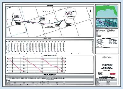
To date, Racal NCS has predominantly used the DHSS in combination with a UWGC to determine pipeline relationship to the seabed. The tools help spans to be measured for rectification, if necessary. USBL positioning for ROV as-built surveys can be erratic in deep water, due to environment and system limitations. Using a doppler-velocity log can help improve USBL stability in this process. Cathodic-protection data is provided by stabbing anodes on the line and multiple electrode surveys. This provides a baseline against which corrosion can later be measured. A pipe-tracker allows the line’s depth of burial to be determined relative to seabed levels. Data Presentation If these additional sensors are used, a higher level of sophistication will be needed to process and present the data. In such a case, real-time eventing and video-indexing should be employed. These techniques provide operators with considerably more information on the pipeline than is presently required by the MMS, Fig. 3.
The survey contractor then presents the final as-built data to the operator and the MMS. The report to the MMS will incorporate charts signed by a registered professional land surveyor. These charts show the pipeline’s plan and profile positions, third-party and block-line crossings, and a list of coordinates describing the line’s plan position. A digital file of the line’s coordinates and features also is submitted. Electronic coordinates provided on the North American Datum 1927 should be derived using the North American Coordinate Conversion program NADCON. Conclusion. In the Gulf of Mexico, the regulatory regime for submission of deepwater pipeline hazard and as-built surveys is the same as that required for the continental shelf. Technology is available to improve the quality and type of survey data presented. The application of new technology, however, is driven by operator need to satisfy existing legislation, and to overcome technological challenges associated with deepwater environments. As increasing numbers of deepwater developments are planned, operator use of more sophisticated sensors and pipeline data management solutions will increase. These solutions are available today, and can help operators build a sophisticated database of parameters associated with the pipeline systems being laid. DWT
|
|||||||||||||||||||||

- Applying ultra-deep LWD resistivity technology successfully in a SAGD operation (May 2019)
- Adoption of wireless intelligent completions advances (May 2019)
- Majors double down as takeaway crunch eases (April 2019)
- What’s new in well logging and formation evaluation (April 2019)
- Qualification of a 20,000-psi subsea BOP: A collaborative approach (February 2019)
- ConocoPhillips’ Greg Leveille sees rapid trajectory of technical advancement continuing (February 2019)

