Technology at Work: E&P projects show positive benefit from recent innovations
TECHNOLOGY AT WORKE&P projects show positive benefit from recent innovations
The innovations described include:
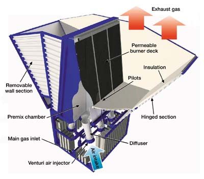
Successful field trials lead to enclosed burner applicationIn the current, environmentally sensitive climate, oil / gas and petrochemical industries are increasingly aware of the need to minimize environmental impact of upstream and downstream activities. Consequently, the flaring of gases during well testing / cleanup and production operations has become a highly sensitive issue. Traditional disadvantages of conventional flaring are well documented and include large visible flames and emitted radiation, as well as incomplete and inefficient combustion which, in turn, produces quantities of NOx. In an attempt to provide a low-visibility, low-emission alternative to existing burners, Expro North Sea Ltd. (part of Expro International Group PLC) in collaboration with FG Engineering Services BV of the Netherlands, has developed the Clean Enclosed Burner (CEB). After successfully completing field trials with NAM in the Netherlands, as will be overviewed here, this innovative burner technology is now ready for deployment in the field. The first two production units are currently being delivered and will be subjected to an acceptance test that will be based in the Netherlands. Further development work is ongoing to prove the unit for sour gas incineration. Description and principle. The CEB employs a high-efficiency, surface combustion technique in which premixed gas and air burns on a permeable woven-metal-fiber mat surface, as part of the system illustrated in Fig. 1. Flare gas is fed to a Venturi air injector at the bottom of the burner system, which draws in air for complete stoichiometric combustion. The Venturi injector is designed to ensure that air ratios from 1:12 to 1:17 are readily achievable.
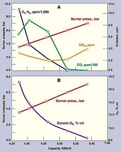
The gas / air mixture is fed via a diffuser into a specially designed premixing chamber, one wall of which is constructed with a permeable, woven-metal fiber matting. During operation, premixed gas and air flows through the mat, where the mixture is then ignited by a pilot burner. The resulting combustion occurs just above the permeable mat burner deck. Heat is then released in convection form, making re-use of energy a possibility for future CEB generations. The metal fibers of the matting provide a large surface area, ensuring rapid cooling of the burner deck surface by flow of the gas / air mixture. The inside (mixing chamber) surface of the burner deck matting never exceeds 150°C. Each CEB module comprises six burner units in two, back-to-back bands (three burners per bank) with a nominal capacity of 186,000 Nm3/day (7 MMcfd). The flame is shielded and directed upward by outer walls which are protected by an insulating layer. Heat radiation to the surrounding area is minimized, and local ambient temperature rises are limited to less than 5°C. To highlight a few key features, the CEB offers high operating flowrates, produced by a modular system; it can be combined with an emergency flare system; and it produces minimal infrared radiation. Maintenance is minimal with all-metal construction and use of standard utilities; it is easy to mobilize, install and operate; and it has a small footprint, with unit foot size of 6.2 by 2.6 m. Deployment. The CEB is a small-footprint, modular system designed for ease of transportation and rapid rig-up. Installation of the burner takes only 5 hr and requires only four personnel with the aid of site craneage. The system is completely self contained except for power for the control system. Frank Skilbeck, development manager of Expro’s Surface and Environmental Systems, commented, "Conventional flaring operations normally result in large visual flames and emitted radiation, as well as incomplete and inefficient combustion. By utilizing Expro’s CEB, emissions of NOx, CO and UHC are significantly reduced, and visible emissions and heat radiation are contained. The environmentally sensitive climate in which all oil companies now operate demands that emissions of all kinds be minimized. In this context, development of the CEB is an interim step toward the Expro Group’s ultimate objective of zero emissions testing." Following more than 100 days of initial trials of an innovative gas burner bed using gas from an industrial source, Expro and FB International built a prototype gas burner suitable for temporary installation at onshore wellsites. This prototype was field tested with the cooperation of NAM in early 1999. During the trial, extensive emission and noise measurements were taken, which quantified exceptional combustion performance coupled with outstandingly low levels of noise and visible flare. A second well-operation, field trial was then planned, again with the cooperation of NAM, utilizing a full-scale prototype capable of efficiently burning 187,500 Nm3/d. This trial was successfully executed in December 1999. The unit has since been successfully utilized on two further well operations, and two production units are now due to be deployed on NAM well operations in environmentally-sensitive or urban locations. These units are due for imminent delivery, while development of units suitable for use in sour gas applications is underway. During the trials, it was proved that the CEB achieved 100% efficient combustion compared with the typical 80 – 86% efficiency of a conventional flare, Figs. 2A and B. There were also significant reductions in NOx, CxHy and CO emissions at all flowrates, thus offering a viable solution to toxic emissions. At optimum flowing conditions, the emissions being monitored were as low as the detection levels of the analyzers utilized by independent, third-party evaluator KW2.
In addition, it was demonstrated that, during daylight hours, at a constant flowrate of 175,000 Nm3/d, no visible light from the CEB was evident to the naked eye, and only a low-level visible emission was apparent during nighttime operations. The gas flowrate was also varied during the test period to establish an operating envelope for the CEB. It was noted that lower flowrates produced a slight increase in emission concentrations; however, this was well within specs. Development history. In July 1998, FG was considering the concept of using surface bed combustion to dispose of large quantities of gas during well testing operations. This was discussed with Expro, and the decision was made to proceed with building a proof-of-concept model. This was not as straightforward as it appears – as Bart Beljaars, FG product development manager, commented, "While surface combustion is often used in domestic and industrial applications, the challenge was to increase the scale from a 30-kW unit to in excess of 100 MW, while being able to handle different gases in an easily-transportable unit." FG then built and tested various models and demonstrated a single-burner bed capable of burning over 30,000 Nm3/d gas. This unit was demonstrated to Expro at FG’s test site on EPZ Co.’s gas-fired power station in the south of the Netherlands. The development testing looked at various aspects of the technology, including flame distribution, gas / air ratios, ease of startup, effect of fluctuating flow, effect of liquids (oil / water) in the feed, and the resulting emissions and capacity. In all, more than 100 days of testing were undertaken. Based on the good results obtained, the unit was shown to NAM, and it was agreed to field test the concept. A second, two-bed burner unit was constructed and tested at NAM’s Krabburen site in March 1999, where – in addition to demonstrating capacity and low visible emissions – third-party emission measurements were also made. These showed the unit to be very efficient, with exceptionally low emissions. Following this, Expro and FG agreed on specs for a portable, high-capacity, six-bed unit with a target capacity of 187,500 Nm3/d, in a single, road-transportable unit. While the design of a production prototype was underway, further testing was undertaken on a single-burner bed to optimize design and investigate increasing capacity still further. This testing showed that resonance leading to excessive noise would have to be overcome, if this was not to be a restriction on maximum achievable capacity. The six-bed, full-scale prototype was tested at the EPZ test site between September and November 1999 to prove effectiveness of startup and natural convection cooling methods. Again, third-party emissions measurements were undertaken, and these showed that the unit exceeded the set design criteria in this respect. The prototype was then field tested at the NAM Dalen 15 site, where the unit
was operated for several days during December 1999 with exceptional results, as previously noted. Following
this successful field test, FG and Expro agreed on the design, and the order was placed for the first two
production units. While these were being designed and built, the prototype was deployed at a further two,
environmentally-sensitive sites in Rotterdam.
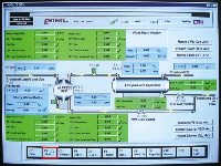
Real-time monitoring of drilling and production operationsControlling drilling and production processes used to require a complex combination of manual data collection, interpretation and analysis. By the time fluctuations were confirmed and process changes implemented, enough time could have elapsed that a new set of issues was likely to have come up. Such were the problems that faced Entest Corp., a division of Plains Energy Services, Ltd., a Canadian – as well as North American – market leader in production testing and underbalanced drilling (UBD) surface control systems. Upon successfully implementing FactoryLink software by USDATA Corp., Entest has been able to significantly increase the level of control exercised during drilling. This control has translated into minimized well downtimes and empowerment of process engineers to make semi-real-time decisions – all while halving the number of people manning field posts. Since process readouts are fed to a remote control post, process control decisions no longer need to be made only onsite, Fig. 1.
Requirements for new software. When Entest engineers were evaluating different software solutions for proposed automation of the drilling process, there were two major requirements that had to be met: 1) control over the drilling operation, and 2) use of supervisory control and data acquisition (SCADA) to control valves, electronic shutoff and separator dump valves, and monitor for high pressure and shutoff as required – once wells are up and running. A system was needed to effectively distribute information to decision makers throughout Entest – on location and offsite. In short, it had to aid engineers both during drilling and during the prolonged unmanned periods when the well, often at a remote location, was extracting gas or oil. FactoryLink software met both of these requirements and was selected for its functionality and ease of programing. During drilling, Entest’s application allows for monitoring: rate of flow coming from the well (both gas and liquid), pressure / temperature of the gas flow and tank levels, and administering nitrogen as required. And in production operations, the operator utilizes a patented two-stage / four-phase separation process in conjunction with Gemini surface control systems, Fig. 2.
Underbalanced drilling techniques are applied, whereby nitrogen and / or oil-based fluids may be used. The closed-loop process separates the fluids once they are evacuated from the well and recycles drilling oil into the well. One problem that can arise is fluctuating oil levels. The amount of oil can decrease over time, and if it gets too low, the operation must be halted while the level is brought back up. Conversely, if oil is struck in the ground while drilling, the fluid level can become too high. In this instance, the well must be shut down while excess oil is separated and stored. System benefits. Processing engineer Dwight Devlin comments on the most immediate benefit of the new software, "You don’t have to have as many people running around the skids, where high pressures and flowrates are present. Everything can be monitored from a central control. We’re deploying two people per shift, down from four. We can see the changes in the way the well is performing, at any time on all of the sensors, rather than just looking at one sensor at a time." Previously, one UBD technician would be collecting readings, trying to figure out the flowrate. Another would be looking at how much nitrogen is going down, while yet another was monitoring its temperature – so it was quite labor intensive. Devlin continues, "Then you would have someone looking at all the individual readouts, and then he would make a decision as to what we wanted to do with the well – do we continue with the same kind of procedure, or do we modify the program a little bit." With the new software deployed, an engineer can look at the well as it is flowing, in real time, and make semi-instantaneous decisions whether to: increase or decrease flow, build up or lower pressure, increase pressure / volume of nitrogen, slow down the drilling – or perform any combination of those adjustments, i.e., it "makes the whole operation a lot more efficient." On any one well, there are five or six different subcontractors working, each sending its own discipline’s set of data to the central control. The engineer on duty can choose which dataset to view on a customizable screen. As Devlin explains, "He can use each of the disciplines individually, or choose to view two items from Company A, three from Company B, and so on. He can have different screens up, completely customizable, satisfying the individual requirements for process monitoring. The process is monitored from either the actual location or the central office. If it’s a pure drilling operation, it’s monitored onsite by the engineer and other personnel; but they also give feedback to the central office if engineers there want to take a look at a particularly critical well. For the in-line operation, it’s monitored only from the central location because it’s an unmanned operation." To appreciate the processes involved during the monitoring, one must realize that some of the wells are located in the far regions of the Canadian outback. Where no land connection is possible, communication between the command center and the in-line location is rendered via a satellite uplink. Each application of the software monitors up to seven wells remotely. The software lets Entest fulfill a Canadian requirement to verify flow from a well on a yearly basis. To satisfy the certification requirements, the well needs to be monitored for several days. With FactoryLink, Entest’s wells are continuously monitored – not just during those times when a certificate is earned. Implementation. Devlin is particularly satisfied with the ease of navigating the screens when setting up the application, and the ability to use single-tag names across the board without having to rename them for different purposes. Because of the software’s kernel aspect, they are able to make use of homegrown programs. Essentially, it allows engineers to collect data from other systems and integrate such data into one central system. When Entest implemented the new system, the concept of automated drilling control was quite novel. The company had never used SCADA software before, so ease of transition was a concern. Devlin took a training course at the local training center in Calgary, and then used the manuals and documentation to set up Entest’s own training package for onsite technicians. "The technicians and other personnel welcomed the new software with open arms," he remembers. Other players in the industry are just beginning to catch up with Entest in
terms of process automation. The fact that the operator’s management recognized the potential benefits of
deploying the software well ahead of the competition gave the company a competitive advantage. Devlin is
confident of their market position, "We’re a good three years ahead of the competition. When we
first obtained the software, no one had anything close to it. People are just now starting to catch up, but
they have not reached the level we now enjoy."
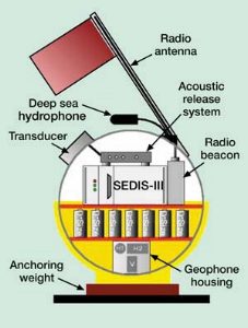
Autonomous seafloor seismographs for wide aperture imagingThe use of Ocean Bottom Seismographs (OBSs) for Wide Aperture Reflection and Refraction Profiling (WARRP) has been shown to be an effective seismic tool in areas of difficult energy penetration, such as below salt, carbonate and basalt layers. It allows 3-D mapping where the geometry of structures is complex, and does so at much less cost than conventional seismic equipment. Equipment. Each OBS comprises a 1.4-ft-dia. glass sphere that is operational to water depths of 20,000 ft. The sphere contains all the electronic components, 51 D-size batteries for power and three gimbal-mounted geophones that record one vertical and two horizontal components, as shown in the accompanying figure. The geophones have a 4.5-Hz eigenfrequency and are placed in an aluminum container at the bottom of the sphere, which is filled with a dense silicon fluid. In addition, a deepwater hydrophone, mounted outside the sphere, also receives seismic signals.
The SEDIS III data logger is a digital stand-alone instrument that allows great operational flexibility in tailoring acquisition design to meet specific requirements. It comprises the recording unit of each OBS and is equipped with a 2.1-GB-capacity hard disk that can record continuously up to 20 days. The instrument weighs 93 lb in air, including batteries. Its sampling rate can be 2 to 16 ms. When compared to conventional geophones, OBS-response spectra is nearly identical up to about 90 Hz, proving suitability of the instrument for normal-incidence and wide-aperture reflection observations. Another option with OBSs is the use of six-channel, vertical-hydrophone arrays laid out either along a profile or in a 3-D grid. Since no heavy equipment (e.g., big streamer winch) is needed, small vessels are sufficient for WARRP surveys. Another advantage is that the OBSs are independent from the sea surface and are, therefore, not affected by wind and wave noise. WARRP surveys using more than 100 OBSs have been successfully performed in rough seas in the North Atlantic and Barents Sea. Operating method. A large number of OBSs are deployed on the seabed along a seismic line or in a grid pattern. They continuously record (on hard disk) all shots fired by airguns over a period of several days or even weeks. Shooting may occur with a conventional air-gun array or one to two large-capacity guns. Each OBS is anchored on the seabed by a 37-lb weight. They are released acoustically or at a pre-programed time. After releasing, the weight remains on the seafloor, and the OBS surfaces at a speed of about 2.3 fps. After surfacing, a radio signal transmitted by the OBS aids in instrument location. The vessel is navigated using GPS, while the true position of each OBS on the seafloor is determined by using direct water-wave arrivals. Imaging below fast strata. WARRP is a relatively new approach to image structures where normal-incidence seismics do not yield satisfying results. GeoPro GmbH – a Hamburg, Germany-based geophysical firm – has wide experience in onshore and offshore acquisition and evaluation of complex structures using WARRP data. In various surveys for major oil companies, the company has shown that the wide-aperture seismic method is a powerful imaging tool for problem areas such as sub-basalt, sub-salt and thrusted / compressed-limestone structures. The basic principle of WARRP is the amplitude burst – when energy is totally reflected beyond the critical angle and no longer transmitted through an interface. Large offsets are required to record at wide angles – much larger than conventional seismic arrays provide. In the Gulf of Suez, Miocene salt layers interbedded in sandstones and limestones generate strong multiples and almost totally reflect normal-incidence seismic energy. This geological setting was generally not imagable with conventional seismic. The WARRP record sections showed that large offsets were required to image such a structure. At large offsets, wide-angle reflections originating from sub-salt interfaces resolved the sediment package beneath the salt layer. Tomographic inversion, forward modeling by ray tracing and full elastic modeling led to a velocity-depth model which was well constrained in both interface depth and velocity, since the model had to satisfy the record sections of many recording stations densely spaced along each profile. Western Greece is a more-complex tectonic setting: a thrustbelt with a salt layer separating several limestone blocks. This structure was unresolvable with conventional seismic due to a karstic-limestone surface and small-impedance contrasts between deeper layers. Since no stacking was involved with the WARRP method, statics resulting from complex geology did not pose problems to WARRP data interpretation. Both cases showed that the WARRP method is capable of imaging seismic problem
areas where conventional seismic data quality is poor. These advanced recording and interpretation methods
allow both 2-D profiling and, where a detailed 3-D image of complex structures is required, 3-D WARRP data
acquisition and evaluation.
Storage area network increases seismology productivity 50%Implementation of the first Fibre Channel (FC)-based Storage Area Network (SAN) in the independent petroleum exploration business has helped Remington Oil and Gas, Dallas, Texas, increase exploration seismology productivity by 50%. "The data is served up so fast that it allows the same number of explorationists to get through half again as much data as before," said Greg Cox, exploration manager. "Our ability to evaluate acreage faster than the competition has made it possible to generate a much larger prospect inventory." The SAN currently provides one terabyte (TB) of disk storage in a RAID 5 configuration and delivers critical information at up to 200 MB/sec. Remington has not experienced a single failure with the 64 Seagate Barracuda 18 FC drives used in the application. An independent energy company, Remington had year-end 1999 proved reserves of 7.2 MM bbl oil and 65.6 Bcf gas. During 1999 and first quarter 2000, it participated in the drilling of 50 wells, of which 43 were successful.
Exploration seismology, data storage bottlenecks. Most of the company’s drilling sites have been identified with the use of exploration seismology, a geophysical method of determining subsurface geology. The challenge of using this technology is that it requires storage / delivery of enormous amounts of seismic data. One square mile of seismic information requires between 55,000 and 75,000 seismic traces to accurately assess its drilling potential. Each seismic trace is composed of 6 to 8 KB of data. This means that just one square mile of seismic data requires storage of on the order of 500 MB of data. Remington’s total seismic inventory consists of 1,600 shallow-water blocks; and for a company this size, it has one of the most extensive, 3-D seismic databases in the Gulf of Mexico. The company’s total volume of seismic data is approaching one terabyte. "In the past," Cox said, "Handling these large volumes of data slowed the work of our exploration staff. We were using five individual workstations with three SCSI drive sets, totaling 20 gigabytes hung on each one. These drive sets couldn’t come close to holding all of the exploration data, so the controllers were cross-wired so that each explorationist could access data on the others’ drives. Interpreters continually moving data from one drive to another slowed down the performance of both systems. In addition, each drive typically was down for a day or two each month due to loose cables or drive failures. All in all, data storage problems served as a significant bottleneck on the team of explorationists that are the heart of our operation." Cox and Robert Murphy, senior VP of E&P, evaluated several possible solutions. They quickly zeroed in on the SAN approach because it makes it possible to eliminate the need for moving data around by hanging huge amounts of disk space on a single server. First, they looked at several Ultra SCSI solutions; these offer maximum transfer rates of 40 MB/s, but typical I/O throughput is severely limited by the overhead inherent in the SCSI approach. The SCSI solutions that Remington evaluated were also quite expensive because of the need for a considerable number of proprietary RAID cards. Investigating solutions. Remington also looked at several FC solutions. This is an integrated set of standards for network and channel I/O interfaces network, and device communication protocols from the physical medium that carries them. High-speed, low-latency, full-duplex, serial FC links presently have maximum transfer rates of 100 MB/s and 200 MB/s with dual loops. In addition, this new technology offers a sure path toward future improvements by keeping pace with inevitable advancements in compatible hardware and software. The standard already accommodates for gigabit and 400 Mbit/s links. Remington selected a Fibre Box (FB) storage system from Dot Hill, Carlsbad, California, with more than a terabyte of Seagate Fibre Channel drives. The FB provides redundancy of all critical components including: four redundant cooling fans, three redundant load-sharing power supplies with auto-failover, redundant port-bypass control cards, and hot-swappable drives to ensure data availability and integrity at all times. The accompanying SES monitoring utility notifies administrators of any problems. Five workstations connected through Vixel hubs use Landmark software for map interpretation, and Veritas Volume Manager and File System for RAID 5 management. High-performance drives. The Barracuda drives feature a 7,200-rpm spindle speed and an internal transfer rate of up to 22.5 MB/s, making them the ideal choice for high-performance workstations and network file-server applications. The drives’ FC interface provides support for 126 devices. The drives feature an average track-to-track seek / read / write of 7.6/8.3 ms, average latency of 4.17 ms, internal transfer rate of 120 to 190 Mbits/s, internal formatted transfer rate of 10.7 to 17.0 Mbits/s, and external FC transfer rate of 100 Mbits/loop. Mean time before failure is 1,000,000 hr, and the drives are warranted for five years. The FB is based on the FC Arbitrated Loop (FC-AL) arrangement – the most economical way to connect a small group of nodes. The subsystems support one or two independent arbitrated loops on their internal backplane. Disks in the FB are dual-ported and, thus, can connect to both loops simultaneously for redundant operation. One arbitrated loop can support up to 126 nodes. The transmitter of each node is connected to the receiver of the next node in the loop, until the last node connects to the first to complete the loop. Each link between nodes may be up to 30 m long with copper cabling, or as long as 10 km with single-mode fiber optics. There is no overall limit to the length of the loop, other than the accumulated maximum distance between nodes. One of the most efficient aspects of the new system is the small amount of required maintenance. Cox said, "The old system required a considerable amount of file cleanup. In addition, explorationists received SCSI errors frequently. In most cases, errors were in the cabling and difficult to track down. The new system has been extremely reliable. The Veritas software eliminates the need for file-system maintenance. The Barracuda drives have never failed. We have had a few software failures, but the RAID LEVEL 5 took over and automatically rebuilt the drives while allowing us to operate in the meantime." The FB and Barracuda drives have given us zero downtime," Cox said. "This,
along with their faster transfer rate and increased storage capacity, has had a major impact on productivity.
While it’s difficult to precisely quantify explorationists’ productivity, my best estimate is that
it is up by 50%. This means that we can evaluate more prospects and do a more thorough job scrutinizing each
prospect. The system gives us a competitive advantage by allowing us to evaluate potential drill sites faster
than the competition."
E&P waste: Manage it cost effectively through landfarmingE. Lance Cole and Sandra Mark, Petroleum Technology Transfer Council Unfortunately, oil and gas production generates waste – not just a revenue stream. However, technology exists for managing E&P waste, and some of this technology was highlighted during a recent field trip presented by the Rocky Mountain Region of the Petroleum Technology Transfer Council (PTTC) during the 2000 Hazardous Waste Research Conference in Denver. For example, company-operated landfills have significantly reduced costs for two producers, and the potential exists for this technology to benefit other companies. Case study I: Landfarming. In 1995, HS Resources, Inc., (HSR) became one of the first oil and gas companies in Colorado to obtain a permit for a non-commercial, centralized land treatment facility (landfarm) for treating and recycling nonhazardous oilfield wastes under land treatment rules established by the Colorado Oil and Gas Conservation Commission (COGCC). The company operates more than 3,000 wells in the DJ basin. In 1994, HSR began replacing buried-concrete, produced-water-storage tanks and closing more than 100 unlined production pits at tank batteries. Generated waste volumes were significant; so the company evaluated several options, ultimately choosing excavation and offsite land treatment at a centralized facility as the most cost-effective. The main reasons HSR permitted its landfarm near Platteville, Colo., were proximity to company operations and lack of sensitive environmental factors (wildlife habitat, surface water, etc.), which influenced the location selection as well. In addition to the required COGCC permit, Weld County required a special permit, essentially a zoning variance, which led to three public hearings and some concessions before an agreement was reached. HSR’s landfarm is a noncommercial facility that can only handle the company’s own nonhazardous E&P wastes. Wastes include hydrocarbon-affected soil, frac sand, drilling mud and tank bottoms. State rules require that wastes not exceed maximum contaminant levels for hydrocarbons, metals and total dissolved solids. The most significant limitation is for total petroleum hydrocarbons (TPH), which cannot exceed 50,000 parts per million (ppm). The landfarm relies on enhancing natural bacterial action through addition of oxygen and moisture. Hydrocarbons provide the nutrients, although other nutrients may be added. Hydrocarbon-affected soil is excavated and transported to the landfarm where it is spread in one-ft, or less, thickness. Soil is tilled monthly to add oxygen, and water is applied to maintain moisture content in the 10% to 15% range. Commercial fertilizer may be added to accelerate biodegradation. When nutrients are added, they are applied at a rate of about 1 lb per cu yd. Treatment is considered complete when hydrocarbon levels are reduced to less than 1,000 ppm. Periodic water and soil monitoring confirm that no adverse soil or groundwater impacts have occurred. Accurate records of soil source and disposition of remediated soil are maintained. Estimated costs for treatment are $4 to $5 per cu yd. This includes costs related to transportation, thin spreading and amendments, as well as performance and environmental monitoring. It excludes the initial capital costs associated with acquisition and improvements to the property. Permiting costs were minimal. When treated material is recycled as backfill, net costs are reduced to about $1 per cu yd. Since the facility began operations, HSR has land treated over 35,000 cu yd of hydrocarbon-affected E&P waste. Initial capital expense was recovered within the first eight months of operation. Case study II: Landfarming and sludge treatment. Similarly, Patina Oil & Gas Corp. maintains a company-operated, integrated E&P waste management facility. Besides landfarming, their facility has a sludge treatment capability to handle oily drilling muds, tank bottoms and other sludges, producing salable product, clear water and residual solids. The water from this process is evaporated in a "special purpose pit" using a simple sprayer system, while the solids are sent to the landfarm for bioremediation. The processing facility contains two soil treatment cells. Soil that is not totally saturated with hydrocarbons is placed directly into one cell. "Dripping wet," saturated soils are placed in a sloped-bottom cement pit. At the lowest end of this pit, there is a chamber with a baffle to allow separation of oil and water. Tank bottoms or BS&W (basic sediment and water) are pumped into either the open tank for immediate processing or into a storage tank for later processing. Material in the open tank is allowed to settle for 24 hr to aid separation. The oil is then pumped to a tank and heated to 160°F. Oil may be further processed through a heater-treater for further separation, then sold. Water goes to the evaporation pit. Residual solids are flushed out with water and routed to a sloping cement pit for mixing with soil, which is then spread in the treatment cells. Soil placement in the cells is limited to depths of 12 to 18 in. With twice-weekly tilling, remediated soil is achieved in less than 90 days. To preserve temperature during winter months, a road grader windrows the soil. To date, Patina has not added moisture. The company uses turkey manure, which is available locally for transportation cost only. All remediated soil is sampled prior to release. Hydrocarbons must be below the 1,000-ppm limit to be released and generally are below 600 ppm. Disposal costs have dropped from $20 per cu yd with liability attached to less than $4 per cu yd with minimal potential liability. The treatment of tank bottoms has produced over 3,000 bbl of salable oil, which has helped defray costs. With the re-use of the treated soil, the cost of the landfarming operation is a breakeven process for Patina. Conclusion. When operations are concentrated, as they are for these
HSR and Patina examples, landfarming has proven very cost-effective. HSR also has analyzed other geographic
areas and field locations and believes landfarming may also be the most effective waste management option for
these cases as well.
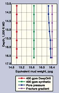
Development of Morpeth field using high-performance, water-based drilling fluidJim Woomer, Drilling Engineer, British-Borneo, Inc.; and Jose J. Perez, Technical Service Engineer, Newpark Drilling Fluids, LLC Development of British-Borneo’s Morpeth field in the Gulf of Mexico, in the southeast corner of Ewing Bank, presented many challenges. Complex hole geometries in this region result from: stacked geological targets, salt structures and – as the field is produced – the presence of depleted zones. All of this – in conjunction with the desire to suppress gas hydrate formation during the drilling phase and the presence of lengthy, highly-reactive shale formations in the production section – would typically dictate use of synthetic-based mud (SBM) to drill these difficult wells. However, the initial development well drilled in the field with SBM experienced unacceptable nonproductive time due to excessive wellbore breathing, and loss of circulation while drilling the production interval. On some occasions, the well would flow back as much as 100 bbl before stabilizing. That well was sidetracked, employing a 20% NaCl/PHPA drilling fluid for the pay section, with mixed results. As a result, an investigation was launched for a suitable, water-based mud (WBM) for this interval in subsequent development wells. The principal criterion for the project demanded a fluid that would provide performance characteristics routinely achieved with SBM, while eliminating the propensity for wellbore breathing and lost circulation. These characteristics include shale inhibition, lubricity, contaminant tolerance and good penetration rates. A typical 8-/2-in. hole interval to be drilled had zones with a maximum pore pressure of about 15.0 lb/gal equivalent (ppge), with a fracture gradient at the 9-5/8-in. casing shoe of 16.2 to 16.4 ppge. Some wells were expected to penetrate depleted zones with differential pressures ranging from 2,500 to 6,000 psi.
Water-based mud recommended. DeepDrill – a high-performance, proprietary water-based mud system – was recommended by Newpark Drilling Fluids. This system, containing a proprietary blend of methyl glucoside (MeG) and polyglycerol (PG), was selected as best meeting the prerequisites. MeG (a corn starch derivative) and PG (a polyol-based compound) are both water-soluble organic materials exhibiting minimal toxicity. The fluid exhibits average LC50 values in excess of 400,000 ppm for the Mysid shrimp bioassay test. This permits disposal of the cuttings and fluid into the Gulf at the rig site without environmental liability. Review of pressure-while-drilling (PWD) data from the initial development well revealed that, with the SBM employed, effective BHPs were very close to the reported casing shoe test under normal drilling conditions. The pump rate was reduced drastically to permit drilling to proceed, but the wellbore breathing issues continued, despite these compromises. Annular hydraulics were rigorously modeled to confirm PWD readings from the SBM well, and to predict effective pressures expected with the recommended system. Modeling indicated that equivalent circulating density (ECD) values for the WBM allowed a wider range of rheological properties and higher pump outputs, along with a greater kick tolerance, Fig. 1. Successful application. Over a period of 18 months, several 8-1/2-in. production intervals were drilled by British-Borneo using the new system. The initial well in the field to use the WBM had first used SBM to drill an "S"-shaped, 12-1/4-in. intermediate hole, with a maximum hole angle of 40°, to set 9-5/8-in. casing at 12,600-ft TVD. The SBM was displaced with the 15.3-ppg WBM system, and a vertical hole was drilled. Drilling rates were hampered initially by bit and BHA balling. Contributing factors to the balling were hydraulics limitations and excessive viscosifier concentrations added at the mixing plant to eliminate settling during transport. Mud rheology was restored, and drilling resumed.
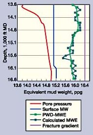
The contamination resistance of the fluid was tested when a salt section about 1,000 ft long was drilled. No adverse effects were seen with the fluid system, and drilling continued without interruption. The well was sidetracked with a second angle build to 33°. No problems were seen sliding off the cement plug and building angle. Intermittent incidents of bit balling were reported when weight on bit was in excess of 25 klb. No further balling of bit or BHA was noted on trips; and optimizing WOB at about 15 klb eliminated the balling tendency. The well was drilled to depth with minimal torque and drag. The directional drilling company calculated coefficients of friction of 0.12 for the cased-hole section and 0.19 for the openhole – comparable to readings attained with SBM. PWD readings matched calculated values and no well control incidents or wellbore breathing were encountered, Fig. 2. An MDT log was run, and the tool stuck on the way up due to overpull restrictions on the wireline and 2,500-psi differential pressure in one of the sands. The well was sidetracked to the top of the pay, and a 7-in. liner was run and cemented. A drill-in fluid was used to drill the pay, and an openhole gravel pack was run for completion. In the second well, 9-5/8-in. casing was set at 13,000-ft TVD at 34°. The angle was dropped to vertical by sliding. Again, the well was drilled with no wellbore-breathing or well-control incidents. The well was plugged back and routinely sidetracked to allow the 7-in. liner to be set at the top of the reservoir, facilitating an openhole, frac-pack completion. The 7-in. liner was run, but integrity could not be established, as the liner had parted. An investigation emphasized the need to ensure effective mud removal prior to cementing. A modified spacer program eliminated cementing problems on subsequent wells. The section was abandoned and a final sidetrack was made for the openhole gravel pack. While picking up the 7-in. liner, GOM loop currents intensified and operations were suspended. After 80 days, operations resumed and the hole section was redrilled, this time using a PDC bit. ROP averaged 35 ft/hr and hole conditions were good. No bit balling was experienced. The 7-in. liner was run and the well was completed. The final well drilled in the field was a sidetrack from the original development well. The wellbore was vertical, and the well was designed to penetrate the previously-produced zone and complete a deeper objective. After cutting a window in the 9-5/8-in. casing, the primary concern was the depleted section to be encountered. The fluid system was enhanced with a variety of sized, lost-circulation materials to improve filtration characteristics. The well was inadvertently sidetracked after a short trip, and drilling resumed. Lost circulation experienced prior to drilling the depleted zone was believed to be caused by mechanical obstructions related to the window, or poor formation integrity just below the window. A 7-in. liner was run and cemented, and a 6-3/4-in., bi-center bit was used to drill through the depleted zone and the prospective pay zone, without incident. Differential pressure was estimated to be 5,000 to 6,000 psi. A 5-1/2-in. liner was run, and the well was completed with a frac pack and placed on production.
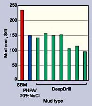
Summary of results. In all, 21,600 ft of hole were drilled in Morpeth with the DeepDrill mud system. Costly wellbore breathing and well control incidents experienced with SBM were eliminated. Torque and drag were similar to values obtained with SBM, despite complex hole geometries resulting from geological considerations. Drill rates were generally 67% of that achieved with SBM, though the use of PDC bits narrowed that gap to 88%. While pump rates were about 100-gpm higher than those achievable with SBM, rig and drillstring constraints limited pump output to 450 gpm. Drilling fluid properties were readily tailored for the specific hole
conditions in each sidetrack, and the contaminant tolerance of the system was demonstrated when fluid
properties remained stable after drilling a long salt section. Severely depleted sands were drilled without
incident. Drilling fluid costs were 40% lower than those seen with SBM, and comparable to those with 20%
NaCl/PHPA muds in the field, Fig. 3; and all environmental compliance targets were achieved. Use of the WBM
system also eliminated potential personnel exposure hazards commonly experienced with synthetic fluids.
|
- Applying ultra-deep LWD resistivity technology successfully in a SAGD operation (May 2019)
- Adoption of wireless intelligent completions advances (May 2019)
- Majors double down as takeaway crunch eases (April 2019)
- What’s new in well logging and formation evaluation (April 2019)
- Qualification of a 20,000-psi subsea BOP: A collaborative approach (February 2019)
- ConocoPhillips’ Greg Leveille sees rapid trajectory of technical advancement continuing (February 2019)

