Hydraulic rig supports casing drilling
Hydraulic rig supports casing drillingUsing oilfield casing to simultaneously drill / case the well is a technical advance helping to reduce costs. Described here are the rigs and associated equipment making this possiblePer Angman, Dale Oveson and Michael Laurent, TESCO Corp., Calgary, Alberta, Canada
Introduction Development of resources in many basins — where reserves are concentrated in relatively small reservoirs — is limited by drilling costs. Over the last few years, drilling costs have been driven to very low levels by: low dayrates for conventional rigs, a sustained effort to apply incremental advances in drilling technology and pressure to improve operational excellence. It is unlikely that significant additional cost reductions can be achieved without changing the way wells are drilled. The realization that there is very little "fat" left in the system stimulated development of a casing drilling system (CDS) aimed at reducing drilling costs even further by making a step change in the fundamental drilling system. The CDS incorporates both surface equipment and downhole equipment that eliminate trips and reduce time delays caused by hole problems and casing running time. Concurrent with CDS development, a new-generation, hydraulically powered and computer-controlled rig was developed to facilitate casing drilling implementation. The integrated drilling rig enhances reliability, safety and flexibility and, at the same time, provides a platform to introduce the casing drilling technology. Casing Drilling System Casing drilling uses standard oilfield casing to simultaneously drill and case the well.1,2 The casing functions as the drillstring to transmit mechanical and hydraulic power to the bit through a drilling assembly latched into the bottom casing joint. A drill-lock assembly is used to transport the drilling assembly, including the bit, and attach it to the bottom of the casing. The drill-lock and drilling assemblies can be either run on wireline or pumped down; they are retrieved from the casing with a wireline. Fig. 1 shows the drill-lock assembly, comprising an axial lock to resist both compression and tensile axial loads, a torque anchor to resist torsional loads, a seal assembly, and assorted features to allow efficient transportation through the casing. These assemblies are retrieved on wireline up the inside of the casing to perform any function that would normally be accomplished by tripping the drillstring. Most frequently, the wireline procedure is used to replace the bit; but it can be used for other operations such as running or retrieving a directional drilling assembly or coring assembly. Casing drilling eliminates the need for drill pipe and tripping the drillstring to change elements on the drilling assembly. In addition to the trip time savings, many unscheduled events are triggered by tripping operations, thus casing drilling reduces drilling time lost due to events such as reaming, fishing and taking kicks while tripping. The CDS provides a more efficient hydraulic system than a conventional drillstring. Circulating pressures are reduced, compared to those typically required with drill pipe, because of the large casing ID. In addition, the relatively uniform OD of the string results in a smaller annular area and provides a constant velocity up the annulus to enhance hole cleaning at a reduced flowrate. The overall result is that better hole cleaning is achieved with decreased rig horsepower and smaller pumps; this increases fuel savings compared to using a similar rig for conventional drilling. While the casing drilling system can be used on any rig, it may be more effectively applied with a rig designed specifically for casing drilling. This is particularly true while the CDS is first being introduced. For this reason, three new-generation hydraulic rigs were designed and built as hybrid rigs that can be used for casing drilling, as well as conventional, rotary-drilling applications; the third has been used as a test rig for casing drilling tool development. Recently, the test rig was commissioned for commercial service as a casing-drilling rig on a four-well program in the U.S. Based on the performance of these rigs, a fourth rig has been designed exclusively for casing drilling. This rig is designed for year-round moving in Canada and includes additional casing-handling automation. Casing can be picked up from the pipe rack and installed in the drillstring without being touched by human hands. This rig spudded its first casing-drilled well in Canada in July. Rig Overview The hybrid rigs, rated for 3,000 m (9,850 ft), consist of a double telescoping mast with integrated top drive and drawworks, an 800-hp triplex mud pump, a Derrick flowline cleaner, a swing-up substructure with an 18-ft floor height and a modular building design.3 Rig equipment is powered by hydrostatic drives and controlled with digital programmable logic controllers (PLCs). All rig functions are controlled through the PLC interface from the driller’s control center (DCC) located in a control room positioned as a third-level building adjacent to the drilling floor.
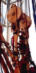
These rigs are designed to facilitate: moves, location construction, rig up, operational efficiency and drilling efficiency for more cost-effective overall drilling operations. Rig equipment is designed into modular buildings that permit stacking to maintain a small footprint for minimal location size. Twenty modular buildings are used to house the power units, engines, electrical equipment, tanks, mud system, control room and other rig equipment. The modular-building design features a large, heated, common drilling-machinery room; and it reduces unit weight per load. In addition, the drawworks is permanently mounted to the back of the mast; this assembly, along with the permanently installed top drive, significantly reduces rig-up / rig-down time. Lastly, this new-generation drilling rig has been designed to facilitate casing drilling, although it can be used effectively with conventional drillstrings. Split traveling blocks with wireline BOP (Fig. 2), split crown, permanently installed top drive and wireline sheaves on the crown are designed to facilitate casing drilling, but also make conventional drilling operations more efficient. Modular Design Fig. 3 illustrates the modular rig layout. The rig equipment is housed in 20-ft´ 8-ft´ 8-1/2-ft modular buildings that weigh, on average, 18,500 lb. The modular rig, excluding the substructure and drilling mast, is dependent on being spotted by a 20-t oilfield picker. Modular design reduces unit weight per load, compared to the bulk of standard oilfield skid buildings. This provides for features, such as deep tank capacity, that allow greater volume per unit length of tank.
The modular, ground-level buildings are placed together to create a large convenient heated indoor work area or common "drilling-machinery" room. The hydraulic power units and engines are located on a second level behind the mast. Similarly, the control room and sub-tool handling room are located on a third level adjacent to the rig floor (driller’s side and off-driller’s side, respectively). The substructure, which houses the rotary table, is a hydraulic, swing-up design that retracts to a lowered height of 5-1/2 ft and a raised height of 18 ft. During operation, the substructure boasts a clear height of 16 ft, which is well-suited for the taller, underbalanced-drilling-stack configurations.
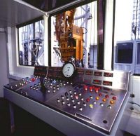
PLC Control System The drilling operation is controlled and monitored remotely from an ergonomically designed driller’s console and drilling data acquisition system in the DCC located adjacent to the drilling floor, Fig. 4. In general, the PLC receives inputs from the DCC and provides power-matching and pump assignments to main functions. The software control provides almost unlimited interlocks and calculations to increase rig safety and efficiency, and simplify diagnosis, remote monitoring and troubleshooting. For example, the drawworks features an auto-driller that provides hands-free operation of smooth, continuous, bit-loading control and an anti-collision system. The following remote and automatic control functions are available:
The rig PLC system includes direct access from a remote location via a satellite phone system. The rig status can be monitored, problems diagnosed, parameters adjusted, and the whole PLC program modified and downloaded from a home-office location. Applications of the PLC are noted in the following component discussions.
Drawworks The drawworks utilizes compact, high-torque, multi-displacement, vane hydraulic motors coupled directly to forged axles on the drilling line drum, thus eliminating the associated need for gearboxes, chain sets, belts, clutches / sprockets and chain guards. This means that the drawworks drum is never disengaged and is driven smoothly in both directions with excellent speed control. This lightweight design allows the drawworks to be integrated into the mast structure; it is not removed for rig moves, Fig. 5. It also functions to extend and retract the mast. The hydrostatic system is used as a dynamic brake by feeding energy back into the hydraulic system to dissipate energy when tripping in. There are no hydromatic or eddy-current brakes on the drilling unit. Lightweight, die-cast, disk-brake calipers mounted directly to the steel tubular frame are used for park and emergency braking. The park brake is spring-applied and air-released. If an air failure occurs, the spring will activate the brake. The service brake is spring-released, air-applied. PLC control. The hydrostatic drive system of the drawworks is controlled through the PLC by a joystick located in the DCC. Since the driller is not bound by a mechanical brake handle location, he can be positioned any distance away from the drawworks, in this case, in the DCC. The hydrostatic-driven drawworks with the PLC control facilitates innovative programing of an automatic driller, anti-collision features, and other interlocks to enhance performance and safety. The auto-driller provides hands-free operation of continuous drilling, while maintaining constant weight on bit (WOB) and maximum drilling rate within settable parameters. Because the auto-driller does not use the drawworks brakes, as do conventional auto-drillers, it provides smooth, continuous control of the hydrostatic-drive system. The auto-driller can automatically pick up the drillstring and "restart" the drilling if the top drive stalls. Safety system. The drawworks safety system includes a floor and crown saver to the limit of the traveling blocks / top drive assembly for anti-collision purposes. Deceleration rates (dependent on string weight and speed) are optimized by the program, unlike with trip or trigger valves in conventional crown savers. In addition, a programed interlock allows the drawworks to accelerate and run within the given speed envelope between floor and crown. The drawworks also has a number of other safety interlocks to protect maintenance personnel and equipment from damage by erroneous operations. For example, the brakes can be released only if sufficient lifting hydraulic pressure for the current hook load is available and sufficient air pressure is available to hold the brakes released. The drawworks can be accelerated only if the brakes are fully released. Shifting the drawworks to a higher speed range can be done on the fly, but is only allowed by the PLC up to a safe load limit. If the hook load increases beyond the load limit while operating at a high or medium speed range, the drawworks speed range is automatically shifted down to a safe level. Top Drive, Other Components A lightweight hydraulic top drive with excellent torque / speed control throughout its operating range is incorporated in the rig. It allows independent, settable drillstring makeup and drilling torque / servo control capability for slide drilling, e.g, the driller can reduce slide friction by rocking the drillstring. Integral pipe-handling and robotic features — power elevators, dual-directional-link tilt, mousehole-extend feature, grabber and remotely operated, dual-ball-mudsaver / safety valve — decrease connection time and increase floor safety. Special interlocks are programed through the PLC system to provide operator safety while working around the top drive and for coordination of top-drive and drawworks operation. The top drive and two-thirds of the torque track are permanently mounted to the mast to reduce rig-up / rig-down time. Eliminating the need to remove the top drive and most of the torque track during rig moves saves up to 5 hr, compared to rig up required with a portable top drive.
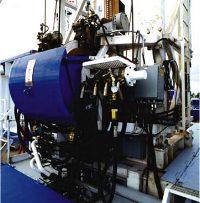
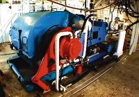
Mud pump drive. The mud pump is driven by a compact, radial-piston, hydraulic motor mounted directly to the crankshaft, Fig. 6. As a result of the direct-drive assembly, the pinion shaft has been removed and the bull gear replaced with a less-expensive flywheel. This feature reduces pump complexity and weight. The mud pump can run at full pressure down to zero rpm to facilitate certain rig operations, such as conducting leak-off tests. An independent, electrically driven lubricating system for the power end assures bearing lubrication over the entire speed range. The hydraulic motor, which runs the mud pump, can be powered from the open-loop system should the closed-loop system fail. This allows mud circulation even if main power on the rig is interrupted. A number of safety features are provided through the PLC. For example, if the mud-saver valve is closed, the mud pump will not start unless overridden by a key switch. A second interlock ensures that mud-pump speed is limited to a safe level, regardless of the number of hydraulic pumps assigned. A third interlock protects maintenance personnel by providing two operating stations — local for maintenance and remote for normal operation. Station selector switches at both locations must agree prior to starting the mud pump. Lastly, an auxiliary, pump-control interlock ensures that start / stop controls of the auxiliary pumps — liner-wash pump, pre-charge pump and power-end-lube pump — are synchronized with the mud pump. Rotary table. A 17-1/2-in. rotary table rated for 150 t is used to support the slip load, rotate the drillstring slowly during "non-drilling" times, i.e., connections, and for emergency backup in the event of a top-drive failure. The rotary table is lightweight and incorporates a hydraulic drive system within the rotary table housing, which eliminates need for an external motor, chain case or drive shaft. It is powered by the open-loop hydraulic system. Electrical system. Two UPS (Un-interruptible power supply) units convert the rig’s generator power (120-VAC, single-phase 60 Hz) to 24 VDC to supply all control and instrument circuits and provide control power should generator power fail. The UPS has sufficient battery backup power to operate all control and instrumentation functions for up to 17 min. This safety feature could, for example, allow 1) the driller to get the bit off bottom to prevent getting stuck, and 2) time to get the standby generator or open-loop auxiliary system running. The UPS also provides clean, regulated power by filtering surge and noise in the power line.
Field Operation Two of the new-generation rigs were introduced into the conventional drilling market and are operating competitively. The first rig was commissioned in August 1998, the second in December 1998. The rigs have drilled both vertical and directional wells; performance has been good, as noted in the accompanying table. The average downtime cumulatively experienced is a low 0.61%. The hydrostatic drive systems, in combination with PLC-based DCC has been proven to work reliably. The ability to control the main drives (drawworks, top drive and mud pump) throughout their respective speed ranges has complemented drilling operations. The top drive, in particular, has complemented tripping. The high-clearance substructure has been used in combination with the underbalanced drilling (UBD) process and its required stack configuration. The satellite link to the rig has been operationally useful for providing field support, which has further assisted in reducing downtime. In general, the rigs have reported few operational challenges. However, with all the automation, it has taken the crew some time to get used to all the features that can be employed to enhance performance. The third hybrid rig and dedicated casing drilling rig were both put to work in July 1999 on casing-drilling jobs. Acknowledgment The authors acknowledge the technical contributions of TESCO Product Development Group, Mainline Industries and Kelon / Ener-Rig in the development and manufacturing of the casing drilling rig. Literature Cited
The authorsPer Angman, Sr. VP of R&D, TESCO Corp., earned a MSc in mining engineering from the University of Lulea, Sweden. He joined TESCO in 1991, as a manager of engineering, spearheading developments within the top drive product group. He has continued in areas of equipment and modular rig design. Before joining TESCO, he worked for several Canadian drilling / service rig contractors as a drilling / equipment engineer. Dale Oveson, Product Manager, Casing Drilling, TESCO Corp., has more than 25 years drilling experience, including offshore SE Asia as a rig superintendent. He joined TESCO in 1993, working with portable top drive operations. He has been working on the casing drilling project for the past year. Michael Laurent, Engineer in Training, Product Development, TESCO Corp., earned a mechanical engineering degree from Concordia University in Montreal in 1996. He has been with TESCO for three years. Copyright © 1999 World
Oil |
||||||||||||||||||||||||||||||||||||||||||||||||||||||||||||||||||||||||||||||||||||||||||||||||||||