Evaluation supports floating LNG safety
PRODUCTION TECHNOLOGYEvaluation supports floating LNG safetyUse of a concept safety evaluation, which determined potential risks of a grassroots offshore LNG plant design, determined that the facility, when built, would be as safe as an onshore LNG facilityMarie Naklie, Mobil Technology Company, Dallas; and Jay Harms and Soo Cheong San, Det Norske Veritas, Houston
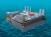
Mobil Technology Company addressed this question in the design of its generic Mobil Floating LNG plant.1,2 Safety was a major priority in the design, influencing key parameters — hull design, process selection, equipment layout and manning levels. Mobil has continued work on development of the design for the last three years. The floating plant is designed to handle 6 million t/year of LNG and up to 55,000 bcpd from 1 Bcfd of feed gas. All production and offloading equipment is supported by a square, doughnut-shaped concrete hull that is spread-moored. The hull can store 250,000 cu m of LNG and 650,000 bbl of condensate. Since they may be moved to produce from several different gas fields during its life, the plant and barge were generically designed. The plant can be used at any Pacific Rim location or similar site, with up to 15% CO2, 100 ppm H2S, 55 bbl of condensate per 1 MMcfg, and a 4,000-ft water depth, Fig. 1.
In order to quantify the risks associated with this design, Mobil contracted Det Norske Veritas (DNV) to conduct a concept safety evaluation (CSE) for the floating LNG plant design. Objectives of the study were:
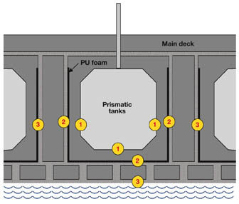
A summary of the analysis is given below. The study covered the risks from downstream of the subsea well manifolds, to the point at which LNG product is loaded onto tankers. The subsea wells, manifolds and LNG tankers were not included in the analysis. In addition, the operator contracted DNV to perform a design pre-certification of the floating LNG plant, with the objectives of assessing compliance with industry standards, and ensuring safety and integrity of the installation during all intended operational modes throughout its design life. The results are also summarized below. The certification firm concluded that the risks inherent in the floating LNG plant design were comparable to those of an onshore LNG plant (same order of magnitude). No factors were identified that would prevent this plant from being designed and operated in a safe manner. When considering all of the elements required for an onshore plant (receiving feed gas from an offshore gas field), the certification firm concluded that this floating LNG design may provide significant risk benefits and greater reliability over the onshore facility. Safety Design Features Throughout its history, the LNG industry has had an excellent record in manufacturing, shipping, and gasification. So, the operator sought to ensure that its floating LNG design would meet the same high standards. Normally anticipated problems associated with LNG production onshore and FPSO-type operations offshore were reviewed by a multidisciplinary team using various hazard analyses. As a result, various features were built into the design. For instance, the hull size allows far more generous equipment spacing than a normal FPSO, due to LNG and condensate storage requirements. The hull shape also has much less motion than a normal FPSO — in fact, almost negligible motion most of the time. In addition, API RP 14C offshore shutdown criteria are used, and no direct-fired equipment is on the facility. Deluge systems, not normally used in onshore LNG plants but which have been proven to reduce overpressures for methane explosions in offshore modules, are included. A single, mixed refrigerant liquefaction process was selected, eliminating the propane / pre-cooling loop and significantly reducing risks associated with LPG storage. The barge design uses double-hull construction as a barrier against collision. Ballast water tanks are located around the hull perimeter, to further protect hydrocarbons from a vessel collision. The stable hull design also permits flooding of a significant number of ballast tanks while retaining buoyancy. LNG storage is a triple-containment system, due to the synergies with the hull construction, rather than single- or full-containment typically used onshore, Fig. 2. LNG storage in inverted concrete cells below deck has virtually no exposure to external fire, explosion or dropped objects that are normal tankage risks.
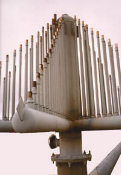
Emergency flaring can handle volumes up to 1 Bcfd safely, Fig. 3. Safe disposition of CO2 and H2S removed from the feed gas is provided. The moonpool provides a protected area for risers entering the plant. The warehouse and maintenance shops are located on the barge, reducing the number of helicopter trips required. Finally, safe havens — fireproofed up to 120 min. — have been provided. They are designed for the maximum explosion overpressure that can be predicted by a model (flame acceleration simulator, or FLACS) used by the oil company.
Prevention of personal injury, illness and/or loss of life, as well as physical damage to property or environment, were primary considerations in planning and arranging the installation. The major protection philosophy for this plant consists of fire and gas detection, shutdown and depressuring of process equipment. Production equipment and control systems are designed with sufficient safety devices and redundancy to prevent or isolate uncontrolled releases of flammable liquids or gases, using a design approach in accordance with API RP 14C. Concept Safety Evaluation The operator had two purposes for performing the CSE. One was to demonstrate that the synergistic benefit to be gained by all of the special design features noted above is a significant increase in the safety level. The other purpose was to determine those areas where effort needs to be concentrated during detailed design to realize further significant improvements in safety. Based on structured qualitative reasoning and quantitative risk analysis (QRA), the CSE evaluated the risks from identified hazards. The QRA portions were performed using standard risk analysis methodology, including frequency and consequence assessments. Because this analysis was performed prior to detailed design, certain design assumptions were required. Analysis at such a stage in design tends to default to conservative approaches. As more detailed information becomes available, results may be revised to reduce such conservatism. The methodology is performed in several stages, Fig. 4. First, the scope of work defines the boundaries for the study to be analyzed, identifying which activities are included and which are excluded. The next stage is to carry out a hazard identification (HAZID) exercise to analyze the facility. HAZID consists of a qualitative review of possible accident scenarios that may occur, based on previous accident experience or judgment where necessary. This exercise provides a list of possible failure causes and scenarios for quantitative modeling.
The third stage involves performing a frequency analysis that estimates how likely it is for accidents to occur. In parallel with frequency analysis is consequence modeling, to evaluate the effects of accidents and their impact on personnel, equipment and structures. Once these stages are completed, the overall risk can be determined. Scope of the study included topside production and liquefaction facilities; LNG and condensate offloading; personnel transport; and subsea risers and pipework. Excluded from the study were LNG and condensate tankers, drilling, wells, support vessel crews, construction activities, towing to location, and startup. The study covered the risks from the subsea well manifolds to the point at which the LNG product is loaded onto tankers An analysis of the risks associated with the floating LNG plant design was performed, and the conceptual design’s features were reviewed to determine their effectiveness in reducing the hazards to personnel. The following major hazards were addressed:
The certification firm determined potential loss-of-life values, individual risk per annum (IRPA), potential asset loss, and potential process loss levels. Table 1 details the relative contributions to IRPA. All risk figures given are for normal operations and are based on annual risk average.
The IRPA for various personnel fell within the general range of 8E-05 to 7E-04. This is a reasonable range for offshore workers worldwide, and it may decrease as more detail becomes available and less conservative assumptions can be made. Not surprisingly, the highest risk category for personnel on the barge is production workers. This high risk is driven by fire and explosion events in the process modules, since production workers spend a large fraction of their shift time in these units. Of the different process areas, the spar deck compressor module — which includes refrigerant heat exchangers and the flash drum — accounted for over half of the process risk. The large contribution to the process risk from this area results from large amounts of equipment combined with inventories available for release. During detailed design, particular effort will be dedicated to "designing out" the major risk drivers. The combination of this process risk with a relatively high occupational risk results in production workers having the highest overall risk. Maintenance employees are exposed to less than half the risk of that of production workers, due to their location in shops that are protected by fire and blast walls. Marine, management and support employees also are protected for significant periods in the accommodations. Note that the risk from LNG tank rupture is exceeding low, due to the triple-containment feature of LNG tank storage. The risk of vessel collisions is relatively low, because of the hull layout and robustness of the concrete design. Risers present less risk. They are protected in the critical area where they enter the plant. Economic risk was calculated by combining capital loss with lost production. Capital loss was determined by combining impact criteria for equipment damage with scenario impact zones. The resulting area of damage was then used to determine a dollar cost for equipment repair and replacement. The economic risk from lost production was based upon oil company and contractor estimates for facility downtime durations associated with different incidents. Production downtime was conservatively assumed to be equivalent to lost production, and no credit was taken for deferred output. Comparison to an Offshore Plant The risk of fatalities for the floating plant was compared to that of an existing onshore LNG facility previously studied by the certification firm. The existing onshore facility that was used for comparison is of similar size (about 6 million t, annually), has similar manufacturing processes and is in the Pacific Rim. However, comparing onshore and offshore facilities is difficult, due to their inherent differences, i.e. different personnel levels, infrastructure, equipment, etc. For example, living quarters are part of the risk assessment offshore, but are normally excluded from onshore evaluations, because personnel usually live off-site. Interestingly, the comparison of onshore and offshore LNG plants resulted in a similar risk picture, overall. The process area on the floating plant is seen as being moderately less hazardous than its onshore counterpart, due to the omission of furnaces (fired heaters) and the decreased likelihood of a release being ignited. In addition, the lack of propane pre-cooling also contributes to a less hazardous process. The lower offshore process risk is offset by the presence of various offshore-specific hazards, such as vessel collisions, helicopter transportation, risers and structural failure. In addition, offshore occupational risk is historically higher than that for onshore workers. By comparing the sum of risks for each of the two facility types, overall risks are found to be similar for total expected fatalities, with individual risk being slightly lower for a worker at the floating plant. From a broader point of view, the floating plant reduces the number of elements in a "typical" offshore LNG production stream from wellhead to tanker by combining the gas treatment and compression platform, pipeline and onshore LNG plant into one complex. This eliminates the need for the platform and subsea gas export pipeline, and it results in associated risk benefits from this reduction in the number of elements. Risk benefits may be significant, because the offshore gas treatment and compression platform required would be manned. The reduction in the number of elements also would be expected to give greater reliability, as there are fewer items that could cause downtime. It is important to note that, from a system-wide perspective such as this, the floating LNG plant design may provide significant risk benefits, depending on alternative development options. Design Pre-Certification The first step in the design verification process was assessment of applicable codes, standards, and regulations; the facility’s mission function; and the environmental and operational conditions to which the facility would be designed. The purpose of the process is to ensure that all important design factors are accounted for. The second step involves evaluation of the structure’s response, due to extreme event environmental loading, operating functional loads and internal deadweights. Virtually all design documents available at this stage of development were reviewed by the certification firm, including such items as P&IDs, equipment layout, piping drawings, electrical load lists, structural documents, model tests, mooring calculations, etc. DNV issued a certificate of compliance in May 1999, stating that the facility design complies with basic safety principles and philosophies contained in internationally recognized codes, standards and recommended practices, as stipulated in the reference document, DNV Design Verification Report. Acknowledgment The authors would like to thank the members of the Mobil Floating LNG Plant Team for developing this technology. In particular, they would like to thank Gil Poe and Duncan Hutcheon for their loss prevention expertise, and Harvey Schulz of Wilfred Baker Engineering, Inc. Literature Cited
The authors
Copyright © 1999 World
Oil |
|||||||||||||||||||||||||||||||||||||||||||||||||||||||||||||||||||||||||||||||||||||||||||||||||||||||||||||||||||||||||||
 Marie
M. Naklie is team leader of Mobil’s Floating
LNG Plant Team in Dallas, Texas. She has 27 years’ experience with Mobil, specializing
in LNG, gas processing, debottlenecking and troubleshooting, primarily in the international
sector. Ms. Naklie holds a BS degree in chemical engineering from Mississippi State
University. She is chairman of the Technical Committee for the Gas Processors Association.
Marie
M. Naklie is team leader of Mobil’s Floating
LNG Plant Team in Dallas, Texas. She has 27 years’ experience with Mobil, specializing
in LNG, gas processing, debottlenecking and troubleshooting, primarily in the international
sector. Ms. Naklie holds a BS degree in chemical engineering from Mississippi State
University. She is chairman of the Technical Committee for the Gas Processors Association. Jay
Harms is a senior engineer within the Deepwater
Technology group in Det Norske Veritas. He has experience in a wide range of risk and
reliability analyses for both onshore and offshore facilities. He received a BS degree in
chemical engineering from the University of Illinois (Champaign-Urbana) in 1992. Mr. Harms
is a member of AIChE.
Jay
Harms is a senior engineer within the Deepwater
Technology group in Det Norske Veritas. He has experience in a wide range of risk and
reliability analyses for both onshore and offshore facilities. He received a BS degree in
chemical engineering from the University of Illinois (Champaign-Urbana) in 1992. Mr. Harms
is a member of AIChE. Soo
Cheong San is a principal engineer in Det Norske
Veritas, concentrating on certification and classification of oil and gas production
facilities. Before joining DNV in 1989, he worked extensively in the oil and gas industry,
focusing on design, construction and operations. Mr. Soo received a BS degree in chemical
engineering from the University of Washington in 1980 and then earned an ME degree in
chemical processes from California State Polytechnic University. He is a member of AIChE.
Soo
Cheong San is a principal engineer in Det Norske
Veritas, concentrating on certification and classification of oil and gas production
facilities. Before joining DNV in 1989, he worked extensively in the oil and gas industry,
focusing on design, construction and operations. Mr. Soo received a BS degree in chemical
engineering from the University of Washington in 1980 and then earned an ME degree in
chemical processes from California State Polytechnic University. He is a member of AIChE.- Applying ultra-deep LWD resistivity technology successfully in a SAGD operation (May 2019)
- Adoption of wireless intelligent completions advances (May 2019)
- Majors double down as takeaway crunch eases (April 2019)
- What’s new in well logging and formation evaluation (April 2019)
- Qualification of a 20,000-psi subsea BOP: A collaborative approach (February 2019)
- ConocoPhillips’ Greg Leveille sees rapid trajectory of technical advancement continuing (February 2019)

