Lube oil blending plant revamps with fieldbus
Lube oil blending plant revamps with fieldbusThe technology provided 3% capital savings, as well as ongoing engineering and maintenance benefitsP. Jacobs, Deutsche Shell AG, Hamburg, Germany, and PROFIBUS International, Karlsruhe, Germany
The revamp became necessary to automate the blending process and to bring the plant up to modern safety and environmental standards. The opportunity has been taken by Shell to reinstrument the plant as well, in a project costing about DM45 million overall. The benefits of using PROFIBUS will continue over the whole life of the plant, bringing even more savings in terms of simpler maintenance, remote calibration and online diagnostics, which are expected to be many times greater than the initial purchase, installation and commissioning costs. Background. The Grasbrook facility is the largest lube oil blending site within the worldwide Shell organization, producing over 350,000 tpy of oil covering 650 products including lubrication and process oils. Raw materials arrive by sea, road and rail, and end products are shipped to customers by the same methods. PROFIBUS-FMS running at 1.5 Mbps was used to connect three important plant areas, thereby reducing wiring and introducing more automation into the processes. Previously, more than 100 different manual hose connections were required for the blending operations. The three plant areas use programmable logic controllers (PLCs) for control, and PROFIBUS-FMS-enabled auto-routing, mass balancing, diagnostics and management information are also provided over the fieldbus. "The original reason for using a fieldbus was to save wiring and make installation easier," says Peter Jacob, new construction engineer. "With PROFIBUS-FMS we gained quite a lot. Single cable communications allowed us to easily commission the remote control services we needed. But there were additional benefits too; for example, even with the best will in the world, plant cabling will accidentally be cut at some time. Of course this will happen whether you are using a single cable or a multicore, but fixing a single bus cable is much easier. A bus system is also easier to document, both during installation and over time as changes are made. We had the ability to add temperature and level sensing via PROFIBUS making the whole system much more powerful."
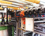
The oil blending plant consists of two sections — the "on-plot" where the new main blending tanks are located together with a new, fully-automated manifold and the control room with a system to provide supervisory and control services. There are 28 input lines for each tank, and pre-mix hoppers are also installed in the facility. Nearby is the "off-plot", where approximately 150 holding and storage tanks are located (Fig. 1). Both the on-plot and off-plot include a multitude of pumps, valves and limit switches, as well as level and temperature sensing devices. There are about 8,000 measurement and control points in all, of which about 90% are digital (Fig. 2).
"Our previous experience with PROFIBUS-FMS provided a solid background for moving toward fieldbus for the revamp," says Peter Jacob, "especially since we realized the PROFIBUS-FMS network could become a fast communications ‘backbone’ under which PROFIBUS-DP and -PA fieldbus networks could be installed." Availability of "gateways" for PROFIBUS-DP meant that the digital I/O could be networked locally as well using AS-Interface, a low-cost and easily-installed networking solution designed mainly for sensors and actuators. "AS-Interface is used extensively in the on-plot but was fundamental to us opening up the PROFIBUS-DP networks to the field," says Jacob. "It meant we could run PROFIBUS cables around the site to connect key locations, then multidrop locally as needed to groups of remote digital devices. The solution is very elegant — a huge amount of hard wiring is eliminated, and around the plant the AS-Interface equipment drops off from PROFIBUS to serve various local digital I/O needs. We standardized on AS-Interface valve islands and I/O modules to IP67 standards and, apart from the AS-Interface power supplies and controllers which need protection, all AS-Interface products are simply attached to the plant superstructure — making installation even easier and ongoing maintenance very simple." The number of PROFIBUS networks and cable routing was decided by analyzing the local area needs of the AS-Interface instrumentation. This was governed first by the maximum network length for AS-Interface of 100 m, and routing was sometimes tricky due to the fact that "not every place is perfect," according to Jacob. "As well as basic physical choices such as where instruments are located, or should cables run to the left or to the right of walkways, the cabling and the housings must take into account maintenance needs. For example, since most housings are exposed to weather, the doors must be hung to protect against prevailing wind and rain when the door is opened for access." Once the location of the AS-Interface networks was decided, the PROFIBUS networks could be laid out. Their location took into account standard needs such as keeping clear of high-voltage cables, but otherwise presented few problems. The PROFIBUS networks are generally between 50 m and 200 m long. A key part of the justification for using PROFIBUS was an accurate cost comparison on the off-plot between traditional wiring and the proposed bus-based solution, arriving at the conclusion that DM700 k could be saved there alone. From this it was possible to predict that a total DM 1.5 million could be saved during the revamp. The then emerging availability of PROFIBUS-PA, which is based on PROFIBUS-DP, provided a bonus, enabling existing 4-20 mA level and temperature analog instrumentation in hazardous areas to be replaced as well. PROFIBUS-PA uses the same protocol as PROFIBUS-DP, providing a fully-integrated communications solution that also offers intrinsically-safe connections and power on the bus in accordance with IEC 61158-2 — the international fieldbus standard for process plant connectivity. "Using PROFIBUS-PA was not in the original plan," explained Jacob, "but it made sense since we were running PROFIBUS-DP around the site anyway. We just multidrop PROFIBUS-PA networks, as required from PROFIBUS-DP, via segment couplers that provide the IS protection and power on the bus. Our plan had been to refurbish and reinstall our original level and temperature instruments, but the manufacturer persuaded us that moving to PROFIBUS-PA was viable. The cost of buying PROFIBUS-PA instrumentation was marginally more, but this extra cost was small compared with the whole-life savings, so we said, "why not change the analog equipment as well?" The segment couplers are located in IP67 housings — often the same ones as used by the AS-Interface networks — to serve various temperature and level transmitters (Fig. 3). Both the AS-Interface networks and PROFIBUS-PA networks communicate with the S5s via PROFIBUS-DP.
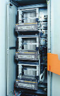
Ten PLCs and eight modules provide the control and I/O facilities. These are strategically located in cabinets that are notable for their absence of wiring; generally only two PROFIBUS cable stubs are visible at each PLC. In one location there are three PLCs in a single cabinet, handling over 2,000 I/O (Fig. 4).
Within the blending plant, the four main tanks are controlled and monitored using local AS-Interface networks connected back to the PLCs by PROFIBUS-DP at 500 bps. Load cells and other instrumentation on each blending tank and drum decanting unit are also linked into PROFIBUS-DP. The PLCs communicate over fiber-optic Ethernet with the control system so that all instruments and I/O can be viewed from the operator screen. Shell’s previous experience with PROFIBUS-FMS benefited the training needs of this site. Plant operators had already learned how to use a fieldbus and are now quickly recognizing the benefits in the new blending system. Maintenance staff now have a good opportunity to watch plant operations from the control room, says Jacob. "Remote ranging and instrumentation calibration can also be performed from the control room, and new on-screen facilities such as ‘copying’ a transmitter’s configuration to other devices in similar plant areas means that commissioning can be much quicker than with traditional techniques. We anticipate that plant maintenance costs will be much lower in the future since a problem can be diagnosed precisely from the control room before a maintenance engineer is called in. This avoids spurious visits to field instrumentation and ensures that the plant can be brought up again quickly after any problems." Overall, 20 PROFIBUS-DP networks are being used at Grasbrook, and there are approximately 50 AS-Interface networks multidropped off these PROFIBUS-DP buses to service the local digital I/O. FB The author
Copyright © 1999 World
Oil |


 Peter
Jacob is a free-lance employee of the Deutsche
Shell AG Gasbrook site. He is responsible for projecting and implementing projects connected
with plant installation (measurement and control techniques, and electricity and power
supply).
Peter
Jacob is a free-lance employee of the Deutsche
Shell AG Gasbrook site. He is responsible for projecting and implementing projects connected
with plant installation (measurement and control techniques, and electricity and power
supply).
