Getting started with fieldbus - a primer
Getting started with fieldbus – a primerUse these guidelines to set up an experimental Foundation fieldbus systemS. Wheatman, Honeywell Industrial Automation & Control, Fort Washington, Pennsylvania
Introduction. Fieldbus technology offers a host of benefits for enhanced data management and process control. Claimed benefits include enhanced interoperability and reduced wiring costs, flexible control implementation and increased access to field information. Despite these benefits, many users are hesitant to move to this new technology. They are unsure about the current state of the technology, how well the instruments will perform, and what changes in engineering approach and process control philosophy are needed to take full advantage of fieldbus. There seems to be a gap in fieldbus documentation. Fieldbus device users’ manuals explain the features of the device, while configurator software explains how to use the configurator. This information is beneficial to those with a good understanding of emerging fieldbus technology. However, documentation to address the new fieldbus user is limited. Just as most computer programmers do not deploy mission-critical applications for computer systems as their first programming exercise, a control engineer should not convert an entire plant to FF technology without first evaluating it in a safe environment. The step-by-step approach to setting up a small prototype system, which this article describes, is analogous to a computer programmer’s first "hello world" program. Background. The FF protocol is an all-digital, serial, two-way communication system that interconnects field equipment such as sensors, actuators and controllers. Fieldbus is a local area network (LAN) for instruments used in both process and manufacturing automation with built-in capability to distribute control applications across the network. FF’s goal is to provide these capabilities in standard products from numerous manufacturers. Toward that end, standards have been created that specify not only the physical mechanisms of communication, such as voltage levels and frequencies, but also the standard message format and content. Control is accomplished by implementing standard function blocks. The Fieldbus Foundation specifies the operation of these function blocks to allow fieldbus blocks from different vendors to interact reliably. Function blocks. The Fieldbus Foundation standard User Application is based on "blocks." There are several types:
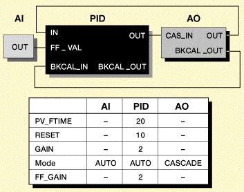
In an FF network, any function block in one device can have a virtual connection to a function block in another device. This capability enables instruments from various vendors to function together. For example, you may connect a transmitter’s PID function block to a function block in an output device. Any combination of these virtual function blocks is possible, regardless of device manufacturer. The configuration software package allows for easy graphical connection, or function block "wiring". For product differentiation, the FF specification allows manufacturers to add custom features to an FF device. To take advantage of these custom features, manufacturers supply Device Description (DD) files with their devices. The DDs must be installed correctly on the host system for the configurator to take full advantage of device functionality. Equipment. An FF network requires the following:
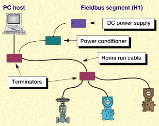
Fig. 1 shows a simple fieldbus network including the host computer with a PC interface card, "home run" cable and field devices. Host tools are available for PCs running either Windows 95/98 or a Windows NT server. The recommended field devices should include at least one input device, such as a pressure or temperature transmitter, and one output device, such as a control valve. With experience, additional devices can be added.
Devices. Many types of devices are available from a large number of vendors. Most devices are bus powered, which means that they draw all of their power from the fieldbus network. Some devices require additional power in the form of AC line voltage or additional DC voltage. Except for the physical connections, operation of "four-wire" devices is the same as "two-wire," bus-powered devices. The FF specification defines two types of field devices: basic devices and link master devices. Link master devices are capable of assuming network control if the host system fails. Basic devices do not have this capability. Every network should have at least one link master device. The PC host communicates with the fieldbus network using a network interface card. Network interface cards are available which use the industry standard AT card form factor for PCs. The interface card connects to H1 (31.25 kbps) networks. Typically, there are two components to the host software: low-level drivers for the operating system to communicate with the interface card, and HMI software which makes use of driver software for data collection and control on the fieldbus. This allows the PC to act as host in an FF system. The host software will need to access files for each device on the network. DDs are data files stored on the PC’s hard drive, which translate the numerical parameter indices to text labels that can be understood by the operator. Configuration functions performed by the host software include device and function block tag assignment, creating function block-based control programs and downloading function block execution schedules. Installation. FF is suitable for installations of any size, including the largest oil refineries. Even so, much can be learned about fieldbus system setup using a miniature group of devices on a desktop. All of the same elements are required. Wiring. The first step in setting up a network is to install the wiring. Because bus-powered fieldbus devices are usually two-wire devices, existing wiring from a 4-20 mA application can be used. Keep in mind that FF devices require a 9–32 VDC power supply and an FF power supply conditioner. Although the same wire can be used, the device is not powered the same way. The preferred fieldbus cable is specified in the IEC / ISA Physical Layer Standard and is called type "A" fieldbus cable. Other cable types can be used for fieldbus wiring. An alternate fieldbus cable is a multiple twisted pair cable with an overall shield. A less preferred fieldbus cable is a single or multiple twisted pair cable without any shield. While this last type of cable may not be suitable for plant installations, it is fine in a lab environment when run over short distances (less than 200 m). In general, three wiring topologies are used: bus with spurs, daisy chain, or star or chick foot arrangement. The best topology depends on the physical plant layout. In all topologies, devices are connected to the network in parallel. Power supplies. Next, select and install a power supply. Fieldbus communications messages appear as 1 V peak-to-peak voltage-modulated signals on top of DC supply voltage. To isolate this signal from the power supply, a power conditioner must be used. A simple power conditioner can be built using the components illustrated in Fig. 2.
Some commercially available power conditioners include surge suppressors and built-in transient voltage absorbers to protect the segment from near lightning strikes, and limit voltage to the devices. To prevent noise on the cable from reflected signals, a terminator is used. A fieldbus terminator can be built using a 1µF capacitor in series with a 100 ohm resistor to block the DC voltage yet allow the signal through. Again, standard fieldbus terminators are commercially available. Most fieldbus devices require 9 to 32 VDC at the device. This can be supplied using almost any conventional power capable of supplying voltages in this range. However, if a 9 V supply is used, losses in the power conditioner and cable may result in a lower voltage at the device which will not be sufficient for it to operate. Therefore, a 24 V supply is recommended. Fieldbus devices draw much more current than traditional analog devices. A typical device may draw approximately 20 milliamps. The user should add the device currents for each device on the network when selecting the power supply. A one-half amp power supply should provide sufficient current for many smaller installations. Host. Next, configure the host, and connect it to the network. To configure the host, first install the software per the manufacturer’s recommendations. Then, set the communications parameters. Refer to the host system documentation for recommended communications settings. Finally, DD information must be specified. To do this, install device DD files on the host and configure it to locate DDs in the specified directory on the PC. Simple tests. Following are some tests that should be performed, in order, once the network has been installed.
Fault simulation. Conventional control systems generate alarms by scanning the process variable of a device and comparing it to a limit set in the host system. If the limit is exceeded, the host generates an alarm. In fieldbus devices, the device performs the alarm checking and generates the alarm. To configure an alarm, set the appropriate HI_LIM or LO_LIM parameter in the function block, and assign it a priority. To test if the device has generated an alarm, read the ALARM_SUM parameter of the function block. If the field device is capable of becoming the link active scheduler of a network, test it by disconnecting the host from the network. After removing the host from the network, verify that the control continues. Next, restore the host to the network, and verify that it regains network control. Remove a device from the network, and observe how other devices behave. If the device is removed, the IN value of the PID should show a "Bad" status. The use of status indicators is how a fieldbus device provides diagnostic information to a host system in the event of a device failure. FB Bibliography
The authorSteven Wheatman is a principal development engineer with Honeywell Industrial Automation and Control. For the past three years, he has been responsible for developing hardware and systems for fieldbus field devices. Previously, Mr. Wheatman held a variety of engineering positions in the medical device industry. He has a BS degree from the Massachusetts Institute of Technology and an MS degree from Pennsylvania State University. Copyright © 1999 World
Oil |
- Applying ultra-deep LWD resistivity technology successfully in a SAGD operation (May 2019)
- Adoption of wireless intelligent completions advances (May 2019)
- Majors double down as takeaway crunch eases (April 2019)
- What’s new in well logging and formation evaluation (April 2019)
- Qualification of a 20,000-psi subsea BOP: A collaborative approach (February 2019)
- ConocoPhillips’ Greg Leveille sees rapid trajectory of technical advancement continuing (February 2019)


