Technical advances improve offshore, deepwater operations
OFFSHORE REPORTTechnical advances improve offshore, deepwater operationsSix new applications of industry advances cover a broad range of offshore engineering, operational activities
From projects recently highlighted at the Offshore Technology Conference and innovative
operations submitted by offshore contractors and engineering companies, these developments
include: 1) application of a more economical Mini-TLP for marginal deepwater fields, 2)
bringing on the world’s first 15,000-psi subsea gas well, 3) practical use of a modular
crane design on offshore platforms, 4) a new database for selling or buying used offshore
facilities, 5) defining / predicting internal ocean waves based on SAR imaging, and 6) how
new tugs control / guide oil tankers through Alaska’s infamous Prince William Sound.
Mono-hull TLP makes smaller deepwater projects practicalThe Morpeth SeaStar developed by Atlantia Offshore Ltd., the first TLP without surface completions, was successfully installed in 1998 in 1,670-ft water at a cost of less than $100 million. The SeaStar was selected by Morpeth field operator British-Borneo because it was the lowest-cost solution for exploitation of the 75 MMbbl oil recoverable from the reservoir. This brief article overviews the Morpeth field development and basic design features of the new, economical TLP concept. Further application of the Morpeth facility concept to the operator’s upcoming Allegheny project in much deeper water is noted, along with extension of the concept to possible applications in several other deepwater development scenarios. The 58-ft-dia., mono-column hull at Morpeth has three radial pontoons 115 ft long, 25 ft deep and tapering to 16 ft wide, Fig. 1. Each pontoon is anchored to the seabed by two 26-in.-dia., neutrally buoyant tendons. Each tendon is latched into individual 84-in. piles driven 320 ft into the seabed. The substructure supports two decks, each 110-ft square on a jacket-type structure. Both hull and deck were fabricated at Gulf Island Fabrication’s yard in Houma, Louisiana. The SeaStar TLP has been designed to the highest international standards and is classed by ABS. Morpeth field development. The Morpeth field provides a specific example of discovery, deferral and development of a deepwater discovery. Although discovered reserves were potentially substantial, proven reserves were not sufficient, nor near enough to existing platform and pipeline infrastructure, to become a development priority, in comparison to other opportunities in the operator’s portfolio. Consequently, after the discovery was made, development was deferred. After a long-offset, subsea tie-back solution was deemed sub-optimal for this field, British-Borneo proposed a stand-alone SeaStar production facility to process oil / gas to pipeline specs. This strategically located platform simplified the subsea system, improved flow assurance, increased recovery and improved the economic attractiveness of future subsea developments in the area. The new field, in 1,670-ft water on Ewing Bank 924, comprises three subsea production wells and a water injection well connected to SeaStar, 1,500 ft away, via flexible flowlines, Fig. 2. Local processing is required for flow assurance, and the subsea trees are linked with pigging loops to enable wax / hydrate removal by pigging from the platform. Close proximity of the wells, made possible by the minimal footprint of the TLP and its mooring system, minimizes pressure drop and thermal loss from the production flowlines. Drilling continued in parallel with platform installation, with only a brief interruption for installation of flowlines and pigging loops at the wells. Similarly, well workover will be by intervention by a mobile offshore drilling unit. The small number of wells, and low workover frequency expected, did not economically justify a rig on this SeaStar platform. The facility provides full hydrocarbon processing for 40,000 bopd and 43 MMcfd gas, accommodation for 18 persons and 30,000-bpd water injection. Pipeline grade oil / gas is exported via steel catenary risers into 12-in. oil and 8-in. gas pipelines that run the 26 miles to the Grand Isle 115 platform, a shallow water facility that is tied into the existing pipeline infrastructure. The Morpeth project received official sanction from British-Borneo in February 1997. Model tests were executed in April, and first steel was cut in July. The keel was laid in October and the pile foundations were installed in November. The hull was loaded out in mid-July 1998 and installed using McDermott’s DB50 derrick barge in DP mode on August 1. After landing the oil / gas export catenary risers on hull porches, the deck was lifted onto the hull on August 8. First oil was produced two months later, after the facility was abandoned three times for hurricanes, one of which passed directly over the platform. Time from project sanction to first oil was 21 months. Concept evolution. Exploration in deepwater areas in the Gulf, like previous frontier areas, has centered on major hydrocarbon accumulations. Thus, early platform technology was focused on large platforms that could accommodate more than 20 wells. There was less interest in developing methods for smaller discoveries. Landmark projects like Shell’s Bullwinkle and Auger demonstrated that each deepwater well could produce in excess of 10,000 bopd. Such high productivity enables good economic performance with only a few wells, provided platform cost can be reduced. Atlantia believed such costs could be reduced by considering lessons learned in the marginal field platform business in shallow-water areas. An objective in developing SeaStar platforms was to reduce platform costs to the extent that many projects could be justified by reserves proved by a single well. The reduced cost / time associated with standardized deepwater platforms can make the difference between years of development studies and a fast track to first production. A large part of the early R&D effort to develop SeaStar technology was funded by the U.S. Department of Energy under a Small Business Innovation Research Grant. The development program was based on three basic premises: 1) Gulf of Mexico infrastructure. A prime objective was to reduce platform size / cost such that competitive GOM infrastructure could be used to construct deepwater platform components. Substantial parts of previous deepwater projects were built in Europe or the Far East and then transported to the Gulf; 2) Flow assurance. Locating the production facility close to subsea wells and shortening flowlines and umbilicals provides operational / cost advantages, while keeping the platform-to-well interfaces simple; and 3) Phased evolution of technology. The Morpeth platform design is based on wet subsea trees, which result in less platform and execution complexity than dry tree systems. A successful wet-tree SeaStar project is a crucial step in progression toward successful dry-tree projects. The Mono-column TLP is a natural marriage of two mature / field-proven technologies: marginal-field platforms and tension-leg platforms. Extensive design development and model testing has confirmed that payloads to 10,000 t can be effectively accommodated by a mono-column TLP without compromising its simplicity. These larger-payload SeaStar models will support combinations of drilling, completion and production facilities. As well counts increase beyond 20 dry trees, the moonpool becomes sufficiently large to warrant a conventional multi-column TLP configuration. As payloads increase beyond the 20,000-t range, floating stability is better provided by hulls with large displacements such as shipshape or Spar structures. Since the stability of TLPs is provided by the mooring, rather than by sheer platform size, mono-column TLPs can be readily scaled down in size / cost to accommodate the economic constraints of marginal fields in deep water. The single column of the SeaStar is transparent to high-energy hurricane forces, while its pontoons provide good tendon separation for effectively restraining heave, roll and pitch. Model testing has demonstrated that the smaller mass and increased transparency enable a conventional tension-leg mooring to remain effective in more than 6,000-ft water with steel tendons. Mono-column TLP design parameters can be adapted to meet field-specific requirements and risk profiles. Several configuration choices are available for well, foundation, tendon and riser systems, e.g.:
As demonstrated in Morpeth, the SeaStar design allows installation to proceed as a series of independent operations, each of which concludes with platform components in storm-safe conditions. This natural segmentation of the installation program allows installation risk to be managed. Future applications. British Borneo’s Allegheny project in the Gulf of Mexico is proceeding, with use of a SeaStar TLP in 3,330-ft water. Installation is planned for summer ’99. Beyond Allegheny, in-house development has resulted in a family of vertically tethered, mono-column hulls to support payloads from 500 to 15,000 t, with subsea and / or surface completions as required by the operator. Repeating the proven hull configuration greatly reduces engineering costs, technical surprises, scheduling and commercial risk. The Seastar is a TLP that produces very small relative motion between hull and riser, unlike competing substructure concepts. This facilitates the use of proven top-tensioned riser and surface trees with direct drill rig well access via a central moonpool. Steel catenary risers may be tied back from subsea wells and are used for export of oil and gas. Alternative deepwater hull types have well systems that are considerably more complex and expensive. Several concepts for broadening the scope of SeaStar applications are under study, as described here. The larger Surface Completion SeaStar hulls include workover drilling capability. This platform has a cellar deck, a lower production deck that also supports the trees and tensioners, and an upper drilling deck. The hull and production deck may be sized to provide adequate area and payload capacity for full process of up to 75,000 bopd and 100 MMcfd gas. Alternatively, the processing may be minimal first-stage separation with gas compression and pumping of hydrocarbons from the smaller Wellhead SeaStar to a local or remote central hub FPSO. The smaller hulls include options with and without surface completions. The minimal Utility SeaStar Platform may be used as a local pig launcher for pipelines from subsea wells to a remote host platform for flow assurance, and also offer well control and / or chemical injection capability, if required, without costly long umbilicals. The platforms are unmanned and no hydrocarbons are taken onboard, so mooring system redundancy is not required. The minimal Dry Tree SeaStar is used to service a few high-pressure wells with surface trees and export multiphase flow. Again, chemical injection and pigging is available. The minimal Wet Tree SeaStar with closed moonpool may have minimal processing and subsea trees or can be used as a pumping platform or hub on a pipeline network. Note. This article was prepared from information
presented by Atlantia authors S. E. Kibbee, S. J. Leverette, K. B. Davies and R. B. Matten
in two papers: 1) OTC 10855, "Morpeth SeaStar Mini-TLP," at OTC ’99, Houston,
May 3–6, and 2) a presentation to the Texas Section of the Society of Naval Architects
and Marine Engineers, "SeaStar — fast track, low cost, proven: The mono column TLP
with many deepwater applications," Houston, Feb. 25–26, 1999. Significantly more
details are presented in these papers and other published literature referenced therein.
Gyrfalcon: Economical development of a 15,000-psi subsea wellAl Williams, VP Marketing, Total Offshore Production Systems, Houston The Gyrfalcon high-pressure, subsea gas well, located in 880-ft water in Green Canyon Block 20, is being developed by Reading and Bates Development Co. (DEVCO) under a farmout from Shell Offshore Inc., Fig. 1. An R&B Falcon subsidiary, Total Offshore Production Systems (TOPS) will have primary responsibility for the field development, using its skills as an integrated turnkey completion and production company, with a team of preferred suppliers that help minimize risk, cost and cycle time of projects while maximizing production.
The Gyrfalcon project. Shell Offshore Inc. originally drilled the gas well, situated in 880 ft of water, as part of its Shorts field. The operator temporarily abandoned the well in March 1997 because wellhead shut-in pressure was in excess of 12,000 psi, which was beyond the capability of existing subsea equipment. Capital costs and the schedule of completing the well vs. the amount of reserves made completion uneconomic. Shell decided to farm-out the development to DEVCO, and the new operator renamed the development Gyrfalcon (JUR-fal-con) for a large falcon in Arctic regions. DEVCO took advantage of outsourcing the development solution to TOPS and kept its staff allocation, one person, and cost to a minimum. The result was the world’s first 15,000-psi subsea well. Basic well properties are: 14,750-psi BHP; expected production, 50 MMscfd; single-zone completion with 3-1/2-in. tubing, frac packed sand control. Engineering and fabrication began immediately upon project award. Offshore installation is scheduled for the summer of 1999, with start-up in the fall. TOPS called on its supplier team to develop the well. It picked the suppliers best-suited to bring the greatest value to the project . For Gyrfalcon, INTEC Engineering provided the project management, flow assurance / project engineering. PETREX provided the first 15,000-psi surface chemical injection package; Wellstream provided the riser; DUCO, a subsidiary of Coflexip Stena Offshore Inc., the umbilical; Sonsub, the flowline jumper; and Cameron, the world’s first 15,000-psi subsea tree. Cal Dive International (CDI) installed the umbilical and subcontracted to Global Industries to install the flowline. New methods supplement new technology. For Gyrfalcon, the team leader determined that the most cost-effective approach was adapting Cameron’s existing subsea technology, rather than designing high-cost, time-consuming new technology. System delivery was guaranteed in 12 months instead of the proposed 36 plus months for a project of this magnitude. Fixed cost for the development was $18 million, a saving of more than $25 million. Several factors contributed to the fast-track schedule. Standardization / optimization of the structural design of the subsea equipment reduced fabrication time, an advantage gained by working with companies that have reputations for performing well on fast-track schedules. To add the most value to the project, TOPS and its suppliers had to have a thorough understanding of subsea systems and their capabilities, and be able to provide critical engineering services. Key CAPEX and OPEX trade-offs allowed for economic field modeling. INTEC provided subsea system design, flow assurance, riser design, installation design, subsea system installation engineering and pipeline design. The team leader worked with INTEC and the preferred suppliers to ensure that the systems were easily installed and handled offshore. The project shows how substantial cost savings can be realized through this integrated involvement in the up-front design process.
Cameron wellhead: The project cornerstone. With no time or funds for development, Cameron repackaged its existing equipment and technologies to produce a functional, low-cost monobore tree, Fig. 2. Essentially, the 15,000-psi, subsea drilling wellhead equipment was repackaged with 10,000-psi SpoolTree technology for a 15k application. Another advantage of the methodology was the use of proven tools and equipment. All were time-tested and factory-accepted, ready for transportation and installation. No new design work was required for the metal-to-metal seals to be used in the tree. This technology was transplanted from seals that were developed by the supplier in a high-pressure, high-temperature development program some years ago for North Sea HPHT applications. In the interest of safety, the well will be cleaned up with the BOP in place—as opposed to the typical Gulf of Mexico deepwater practice of setting the tree before the well is opened for cleanup. While this setup requires more time for tool trips, having the BOP in place provides added safety. Another variation in the Gyrfalcon project is the decision to place the choke on the platform instead of at the wellhead. While the choke at the wellhead facilitates the gradual opening of the well during startup, thus sparing valve gates and seals the ravages of high differential pressure, TOPS did not believe it was necessary to create a 15,000-psi subsea choke. High-pressure effects on chemical injection, umbilicals. With a 15,000-psi well, systems had to be developed for chemical injection and umbilicals. Gyrfalcon’s gas production will flow through high-pressure, 6-in. pipe to Shell’s Boxer platform, 2.8 miles away. With fluid temperatures of 180° and sea temperatures of 60°, hydrates are a concern. PETREX was contracted to provide a continuous methanol injection system for the 15,000-psi well. Because hydrate suppression is critical and the pump must work continuously, the supplier chose a pump with a highly durable metal diaphragm. Two methanol pumps will deliver about 60 bpd of methanol at 13,775 psi. The system was installed on the Boxer platform; and Shell will operate the well on DEVCO’s behalf. The team leader wanted a subsea control system that would require minimal operator intervention and maintenance, thus a direct hydraulic control system was selected. An umbilical system had to be developed for the nearly three-mile tieback, with working pressures from 3,000 to 15,000 psi. DUCO’s complete umbilical system includes the umbilical, comprising nine super duplex steel tubes, termination sled and flying leads to the subsea tree. In testing, the tubulars underwent pressures as high as 18,750 psi. The supplier’s engineers developed procedures to deal with the difficulties typically associated with welding thick-wall tube. Pipeline installation, teamwork. Handling subsea equipment offshore is difficult and cumbersome and often involves keel hauling of equipment and managing limited space. Often, the best solution for subsea construction is use of more than one vessel. Therefore, it is important that there is a willingness and ability for construction companies to not only supply their own vessels, but also act as a general contractor for other subsea construction activities. CDI is just such a contractor. It subcontracted with Global Industries to install the pipeline utilizing the reel pipelay barge Chicksaw. Global layed 2.84 miles of 6-in., X-65, 11,850-psi design pressure flowline to tieback the Gyrfalcon gas well to the Boxer platform in Green Canyon Bock 19. And CDI will install DUCO’s steel-tube umbilicals utilizing its Multi Service Vessel Witch Queen. By aligning itself with strategic suppliers, supporting the development of innovative technology and moving quickly to make decisions, TOPS has demonstrated the value of outsourcing field development. The key features for operators are minimizing high technical risk, large commercial upside and a need to develop the project in the shortest possible time to provide the best returns. Outsourcing mitigates risk while giving the operator the greatest cost control. A record subsea well and projected savings of more than $25 million and 30-plus months are the result. Maybe, more important, the methodology of the project is what should be of interest to oil
and gas companies. As operators respond to the downturn in oil prices, reduction of internal
staff and marginal field difficulties, more and more responsibility for the economic
viability of a development will go to outsourcing contractors.
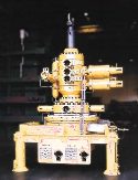
Modular crane adapts to multiple localesResponding to industry’s demand for lower development costs at marginal fields, as well as cost reductions for general operations and maintenance on existing platforms, French manufacturer Hydralift MAPE has developed what it calls the first modular offshore crane. The 40-t unit is targeted to higher lifting capacity chores, such as coiled tubing procedures and support of drilling operations. Company officials said the crane ensures better use of logistical resources, because it is reusable, i.e., it can be relocated. Recognizing that heavy lifts are very time-specific operations, this modular unit is designed to be a temporary "dismantleable" piece of equipment. Thus, it eliminates the cost of hiring a crane vessel and removes the need for initial capital investment in a new platform crane. For instance, on an older installation, the operator merely needs to retain an old 5-t crane for routine work. If, at some point, heavy lifting is required, this same 5-t unit can be used to lift the eight-module 40-t crane onboard. Within 6 hr, the modular system can be erected and operated. A similar time period is required for dismantling and removing the unit. At new installations, the manufacturer recommends that operators initially invest in only a 5-t crane, which represents about 25% of the cost for the modular unit. As work progresses, the modular heavy-lift crane can be installed temporarily, on request. A good example would be at a new marginal field, where production may be extended after a successful early output phase. This would require drilling new wells, and modifying or expanding production equipment. The modular crane is well-suited to this phase as part of a "global concept" to install modular items, like a derrick or process equipment. Afterwards, it can be dismantled easily and, in most cases, reused on other platforms. The concept is also highly applicable to revamping of older installations, where only an
upgrading of existing lifting capacity is required to install the modular 40-t unit. Already
in use in Africa, this crane has its own fully independent, diesel-driven power source.
Various options to the basic unit also are available to meet specific requirements for
individual operators. Finally, maintenance of the crane can take place onshore, resulting in
yet another cost-cutting feature. Re-use of production facilities: An option for new fieldsThe oil industry has been using offshore platforms for exploitation of oil / gas reservoirs for several decades. On depletion of a reservoir, the platform will no longer be required, and it is to be removed from its location. Field operating agreements generally state that the operator must maximize asset recovery, while licensing / governmental bodies require that operators investigate all options for re-use or recycling of the platform after field life has ended. There are several options available to fulfill these requirements, including: disposal at sea (no longer allowed in Europe), scrapping, selling re-usable components, and re-use in another field or for another purpose, e.g., a training center. Later in this presentation, an organization is described which has developed a database to facilitate the timely communication between operators planning near-future facilities / component decommissioning and potential users / buyers. Re-use is a realistic option. As design life of a platform’s components normally extends well beyond reservoir life and the platform topsides at such a time are normally in a relatively good condition, re-use of components is a realistic option. However, re-use is not yet a general option considered by operators. One reason is the technological advancement this industry has created. We are proud to build "new," and we see re-use as "second rate." This is not so in aviation and shipping industries. Or, to make it closer to home, most of us live in a "re-used" house. But changes in our industry, especially recently, concern oil price and not the process of oil, water, gas and solids separation. This dictates a more realistic view on asset allocation for new-field developments. If we can accept that a used platform can be refurbished to an acceptable standard at a fraction of the cost of new-building, it may well make the difference for economic feasibility of new-field developments. Structured data required, timing. An obstruction to operators investigating the selling of facilities is that the interested parties or their requirements are unknown. Likewise, for potential buyers, if they can find any information on platforms for sale, it is not structured, i.e., organized / managed, for a particular purpose; and it is very limited and based on a platform-for-platform basis. Mostly, the facility characteristics are fragmented and not relevant to a potential buyer. To serve the purpose, the information should be structured such that it allows the finding of available facilities that match the desired field or production requirements. It should also allow the making of a genuine comparison between re-using / refurbishing an existing facility (or its components) or building new. Timing adds to the benefits. Only when the date of field depletion nears will an operator start looking for potential buyers. A new-field operator will choose between new-built or re-use, up to five years ahead of first production. If engineers could be aware of a platform scheduled for shut down in the near future, and that platform would match requirements for the new reservoir, both parties would benefit significantly. The new reservoir operator will benefit, as planners / engineers can:
The present operator will benefit from an early transaction by knowing:
A globe-spanning database. In recent years, Dutch research institutes TNO and ECN, coordinated by Kvaerner, have been developing software that allows the building of a globe-spanning database of platforms to be decommissioned within five years. The data is purpose-structured to the requirements indicated above. An organization called the WEB Platform Brokers (WPB) will operate the database on the internet as of April 1999. The database allows new-field operators to enter field criteria or facility requirements — online — and the software will — again online — match this input with available units, indicating possible shortfalls in capacity. The software can generate an estimate for refurbishing and relocation costs, allowing initial comparison between new-build or re-use. The operator can, at this point, acquire an access code from the web-operator that will allow a more detailed match, revealing the in-depth data available on the chosen platform. This data includes production and maintenance figures, construction drawings and even 360° "bubble views" of the platform and its modules’ interiors. This system thus allows an initial visual inspection without having to fly out to the offshore location. WPB is headed by Otto van Voorst, former VP operations of FPSO operator Bluewater. The
company’s staff experience facilitates independent, expert assistance and mediation
services between seller and buyer to the point of an initial agreement. Further, the
organization can render independent advice on transportation / installation requirements to
the new owner. It is currently discussing with operators the shut-down schedule of their
facilities to load into the database. A demo version of the system is approachable on
internet address: www.WEB-Platform-Brokers.com. Internal wave analysis using SAR and non-linear modelHafedh Hajji, MeteoMer, Argens, France It is well known that tidal movement over a significant topography feature creates internal waves of large amplitude. The dynamics of these waves, their effect on the various physical ocean processes, and consequently, the theories used to describe them differ, depending on how the movements are generated over a continental sill or slope. Where there is a sill, the tidal current is, in general, assumed to be alternating and weak on either side of the barrier. During the ebb, a solitary wave is formed. Along its movements, the solitary wave develops into a group of solitons (see definition below), creating change in the sea roughness. For operational purposes, the French Navy, for instance, needs to forecast the temperature and salinity fluctuations which influence underwater sound propagation. Moreover, many marine operations are perturbed by the presence of "internal" waves (Andaman Sea, Guinea Gulf, etc.). These waves are generated at the continental shelf by incoming and outgoing tides. To assist these marine operations, MeteoMer within the CLAROM group is developing an operational system — based on Synthetic Aperture Radar (SAR) image analysis and hydrodynamic modeling — for simulating the internal waves generated by barotropic tides on a continental shelf in the presence of stratification. The ERS1-SAR image acquired July 23, 1994, at 0918 hr corresponds to a generation area of internal waves on the Angola coastal area, Fig. 1. Not far from this area, the Omega (an oil exploration platform) was shifted 4°. Tidal currents generate the three packets of internal waves shown in Fig. 1. The wind deduced from: the ECMWF analysis model, Topex-Poseidon measurements, and the image itself, indicates very low speed (less than 3 mps), this is confirmed by the presence of many dark areas. In addition to low wind, wind sheltering can cause the large dark area situated on the coastal zone. Measuring the packet spacing, and assuming a tidal periodicity (semi-diurnal in Angola area) between them makes it possible to calculate the wave-group velocity (50.3 mps) which can provide an estimate of either the depth of the thermocline or the density contrast, Figs. 2 and 3.
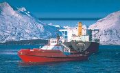
To predict the observed solitons in the SAR image, the nonlinear transformation of the internal tide on the continental shelf is modeled in terms of the Korteweg-de Vries (K-dV) equation, including horizontal variability and dissipation. This model was first developed and applied on the Australian North West Shelf by Holoway et al. (1997). The comparison between in-situ measurements and simulations showed a good agreement. Note. Soliton-like waves, often called internal solitary waves, are nonlinear waves of permanent form. They are frequently observed to form in the stratified ocean as a result of oscillatory flow over topographic features or from the evolution of large-amplitude, long-internal waves. Solitons are water waves that propagate beneath the ocean’s surface, along the boundary layer between water of greater and lesser density. Acknowledgment A part of the financial support for this system is provided under the ANAIS project by the FSH (French Oil Organism). MeteoMer thanks the European Spatial Agency for providing the SAR images. New tugs escort tankers through Prince William SoundAlan Haig-Brown, Seattle, Washington In the Port of Valdez, North America’s northernmost ice-free port, more than a million bopd are transferred from the 800-mi-long Trans-Alaska pipeline to tankers bound for refineries. A small navy of specialized vessels, crewed by highly trained personnel, guard Prince William Sound from a catastrophic oil spill. The majority of these vessels will be provided by Crowley Marine Services under contract to Alyeska Pipeline Service Co. — a consortium of oil companies shipping through the port. These vessels include a range of oil-recovery barges, skimmer boats and escort tugs. The prevention challenge. The simple lesson learned from the Exxon Valdez spill is that it is much easier to prevent tanker spills than it is to clean them up. To that end, the route that a loaded tanker, escorted by tugs, must transit to get safely to open water has been divided into three segments, Fig. 1. The Port of Valdez segment stretches WSW 8 mi from the terminal through the 3-mi-long by 0.8-mi-wide Valdez Narrows constriction. From there, the widening Valdez Arm extends SW 12 mi to Buoy Nine, near Glacier Island. The Central segment takes a laden tanker past Bligh Reef, then 25 mi S to near Montague Pt., where the South segment begins. This passage trends SE 12 mi through Hinchenbrook Entrance, past Seal Rocks and out to open sea. Once 17 mi out, the tanker is the captain’s sole responsibility. New tug power. The first leg is the most confined. It is here that a new, 155-ft tractor tug, the Nanuq, earns her keep. At 10,192 hp, she is the largest, most powerful tug of her type in the world. Her cycloidal drives are a series of adjustable, hydrodynamic blades extending more than 9 ft below the hull and rotating on a pair of horizontal plates. By changing blade pitch, the tug captain can quickly direct full power in any direction. Under state law instituted after the Exxon Valdez oil spill, tankers are required to use "the best available technology" to prevent future spills. The Nanuq is that technology. Putting a high-tech plasma line from her winch to the tanker through a super-strong lead located mid-stern on the tanker, the tug trails along astern.
If the tanker loses power or suffers rudder failure, the tug’s job is to get her back on course. Using a series of well-practiced maneuvers with the tanker pilot (Fig. 2), the tug captain can stop the ship from turning out of control or running aground. The tug’s cycloidal drives are located forward, allowing room for a huge, barn-door-sized extension to project into the water along the keel line aft. By working the line off a winch located back of the cabin and running through a staple on the aft deck, the tug can turn 90° to the line to exert a powerful drag on the ship. By increasing blade pitch, it can apply even greater force at the required angle to the stern. With a line-pull monitor mounted in front of him, the tug captain can deliver the precise pull the tanker pilot requests. Depending on tanker size and particular dangers in the area, speed limits vary between 5–10 kt. With a drag-enhanced pull of about 200 t, the tug is capable of controlling even the largest tankers at these speeds. The Northern Sector. The Nanuq is not alone in her work. Before the tanker leaves port, a pre-escort conference is held by radiophone between tanker master, pilot and escort vessel masters. Depending on winds and tanker size, two or three escort vessels may be assigned. These usually include at least one cycloidal tug. Recently, escorting a 180,000-dwt tanker required three tugs: the 150-ft, 7,200-hp Sea Voyager and the 136-ft, 7,000-hp Bulwark were escorts, while the Nanuq, after assisting the ship off the dock, took up her place tethered 300 ft astern. In the deep waters of Port Valdez, the ship and tug were permitted a 10-kt speed. As they entered the 0.8-mi-wide Narrows, the ship dropped her speed to 5 kt. Although they do these escorts hundreds of times, tug crews must keep alert for any variation in the ship’s wake or radio call-to-action from her pilot. As the ship makes way, the pilot reports all her movements to the Coast Guard’s Vessel Traffic Safety (VTS) and Alyeska’s shore-based traffic-control center. Vessel movement within Port Valdez is radar monitored in the Coast Guard station, while those in Valdez Arm are tracked by remote tower-mounted radar at the Narrows’ south end. The ship is required to stay within strictly prescribed Maneuvering Zones and Track Lines. She must notify VTS of any movement beyond this zone. A 300-ft variation outside of the prescribed Optimum Trackline must also be reported. When winds in the Narrows are over 30 kt, transit of tankers greater than 150,000 dwt is prohibited. At 40 kt, all tanker passages are prohibited. The Central Sector. To escort the 180,000-t tanker, Nanuq drops her tether line from the tanker’s stern at Buoy Nine, the demarcation between the Northern and Central Prince William Sound zones. Before 1989, tankers could drop their pilots and escort tugs at this point. South of Valdez Arm, the route opens to Prince William Sound proper. The tug will now serve as tanker escort for the next leg, along with another vessel. With a north wind, there is a danger of ice being blown into shipping lanes from Columbia Glacier. When ice is present, the tug will travel ahead of the tanker in constant communication with the pilot on the tanker’s bridge. Once clear of the Narrows and into Valdez Arm, the tanker increases speed to 8 kt; at Buoy Nine, she ups that to 10 kt. As the ship comes abeam of Bligh Reef, Nanuq passes off her escort role to the Bligh Reef sentinel vessel. A speedboat comes out to take the pilot back to Emerald Isle base to await an inbound ship. Once again under the sole command of her captain, in more open but still sensitive waters, the heavily laden tanker is protected by two tugs: the Bulwark holds starboard position and the sentinel tug, a powerful former oil-supply vessel, is to port. After delivery in early 2000, the sentinel vessel will be replaced by one of Crowley’s new Prevention and Response Tug class vessels. Currently being built at Dakota Creek Industries in Washington state, these versatile 140-foot tugs will have 10,192 hp, like the larger Nanuq. Rather than cycloidal drives, they will be propelled by aft-mounted azimuthing Z-drives. These have conventional propellers mounted on hubs to allow thrust to be directed 360°. These tugs will serve a variety of functions in Prince William Sound and have oil-spill recovery and storage capabilities for up to 43,000 gal. The Southern Sector. As the tanker passes south through Prince William Sound, it is handed off from the Naked Island sentinel tug to the Hinchenbrook sentinel tug. The Bulwark, which has been with her from the Valdez dock, continues alongside. Hinchenbrook Entrance is the main entrance to, or exit from, Prince William Sound. It is about 6 mi wide and clear, with the exception of Seal Rocks. In addition to its duties as sentinel tug, the Hinchenbrook tug, remains on station to act as a rescue tug with both towing and spill-recovery capabilities. All laden tankers transiting the pass into the Gulf of Alaska are required to have at least two escorts. While it is not required that these tugs accompany the tanker to sea, they stand by, ready to assist, until the ship is 17 mi offshore and safely on her way south. The tanker captain contacts the Hinchenbrook tug and Valdez VTS to tell the team of vessels that have accompanied her that another cargo of Alaskan crude is safely at sea. The whole exercise is a marvel of cooperation between shore-based and on-board personnel employed by the U.S. Coast Guard, Alyeska Pipeline Service, Alaska State Pilots, various shipping companies and the officers and crews of the Valdez fleet. Note: Alan Haig-Brown, a freelance writer, can be
contacted at: 604/520-6748 or http://home.istar.ca/~haigbrow/index.htm. For more information
about Crowley Marine Services, call Ryan Malane, 206/443-8523.
Copyright © 1999 World
Oil |

- Applying ultra-deep LWD resistivity technology successfully in a SAGD operation (May 2019)
- Adoption of wireless intelligent completions advances (May 2019)
- Majors double down as takeaway crunch eases (April 2019)
- What’s new in well logging and formation evaluation (April 2019)
- Qualification of a 20,000-psi subsea BOP: A collaborative approach (February 2019)
- ConocoPhillips’ Greg Leveille sees rapid trajectory of technical advancement continuing (February 2019)

