TECHNOLOGY AT WORK: Five ways to improve field operations and facility design
TECHNOLOGY AT WORKFive ways to improve field operations, facility design
Leveraging resources should benefit independent producersLeo A. Schrider, Petroleum Technology Transfer Council* Partnerships and alliances are an increasingly important part of how the U.S. petroleum industry operates. While the general public certainly can see this with the recent spate of mergers among major producers, such actions are common with independents. Because collaborations can be an efficient means to leverage limited resources, they are becoming critical for independents, including my company, Belden & Blake, where we are currently leveraging our in-house dollars and expertise on state, federal and GRI-subsidized R&D initiatives. Like others in the petroleum industry, the Petroleum Technology Transfer Council (PTTC) leverages its resources with various organizations. In the process, we are able to expand our efforts to bring relevant information about practical, field-tested technologies to independent producers, their consultants and vendors/service companies. A few examples illustrate the diversity of these collaborations and the benefits they offer independent producers. Bottom-line results in case studies. You need look no further than this magazine to find a prime example of collaboration by two entities trying to better address independents’ concerns. As a supplement to the September issue, World Oil and PTTC teamed up to publish Petroleum Technology Digest. This new publication is a compilation of nine case studies on upstream technologies proven to be cost-effective. These field-tested results, developed by working closely with producers and the vendor/service community, are a tremendous resource for those seeking technical solutions to their exploration and production problems. Independents have consistently told PTTC that they want more technology case studies in print, at workshops and conferences and on our Web pages. By collaborating with World Oil and its considerable resources, quality case studies can be disseminated to a much broader audience of independents throughout North America. Since this was the first in a series of anticipated issues of Petroleum Technology Digest, with the next one scheduled for publication in May 2000, we are now soliciting abstracts for consideration in future issues. Send in a one-page abstract to PTTC by January 7 if you are interested in sharing information about your profitable field application and letting others benefit from your experience. Hands-on computer training. Future profitability in the E&P sector depends on, among other things, increased efficiency. The use of petroleum E&P software, when combined with other tools and experience, can help producers get better answers, faster. While staying current with rapidly evolving E&P software requires both time and money commitments, there are a slew of targeted, collaborative resources available to help producers. The Rocky Mountain Software Training Center, on the campus of the Colorado School of Mines (CSM) in Golden, offers regional independent producers the chance to benefit from an extensive agenda of low-cost, hands-on E&P software training on widely known packages (both PC and Unix platforms). It is another example of a collaborative effort – PTTC, CSM, the American Association of Petroleum Geologists and private donors co-founded the Center – the first of its kind established at a university offering four-year degrees. The Center provides access to nearly 100 software packages, all of which are available for demonstration and hands-on learning, even if a specific training course is not part of the curriculum. Many of these software packages also are also available through one of PTTC’s other nine regions. Most courses offered at the Rocky Mountain Software Training Center go beyond just learning to use specific software packages – they cover the whys and hows of the technologies themselves. Special funding from AAPG allows selected courses to be offered at reduced prices, making them even more attractive to hard-pressed operators and consultants. If you cannot make it to one of the regional resource centers, or do not know where to start, you may want to order PTTC’s Petroleum E&P Software Sampler, a low-cost informational CD-ROM providing applications and pricing comparisons for about 50 software packages. Basic field operations. In its presentations that address hands-on operational needs, PTTC often holds workshops cooperatively with local petroleum organizations. One example is its relationship with Oklahoma’s Commission on Marginally Producing Oil and Gas Wells – commonly referred to as the Marginal Well Commission (MWC). While it has been serving Oklahoma’s independent and marginal well producers since 1992 through a variety of operations-oriented workshops, MWC also offers other informational resources. It has a large library of videos and informational material available for checkout by individuals throughout the U.S. MWC also distributes professionally edited videos of their more popular workshops (advanced plunger lift, due diligence, Oklahoma Corporation Commission forms and well-plugging operations), along with workshop notebooks on nearly 20 topics. From the beginning, PTTC’s South Midcontinent Region and MWC have worked together to serve Oklahoma’s independents, and even further cooperation is planned for the future. Although MWC targets Oklahoma operators, Executive Director Rick Chapman told PTTC, "If producers in other PTTC regions are interested in our workshops, they should contact MWC – together, we’ll find a way to bring them to area producers." MWC is also finalizing The Lease Pumper’s Handbook – a refresher manual for experienced pumpers and an invaluable resource for new pumpers. Solutions from the field. More than 100 technology workshops for independents are held around the country each year and are either sponsored or cosponsored by PTTC. These events, which reach thousands of independents, are the best examples of our collaborative efforts between PTTC’s national headquarters, its ten regional resource centers, and other organizations. Since some independents have limited time or resources to attend these workshops, we are working hard to develop concise, two-page summaries of the main discussion points and problems addressed, with contact information for key speakers and other contributors. In July, PTTC issued Solutions From the Field, a compilation of 14 such summaries of regional workshops held during the last two years. It updates the "Best of PTTC Workshops" report that came out in 1997. Both are available from PTTC, either hardcopy or electronically. Additional summaries have been added each week since August to PTTC’s web site (www.pttc.org). Since its founding more than five years ago, PTTC’s goal has been to
serve as the independent producer’s "bridge to solutions," connecting those with needs and
opportunities to those having potential technology solutions. Particularly with the latest oil price crisis,
we’ve seen that you can’t do it all by yourself – those in the petroleum industry need to use
as many resources as possible to stay current and competitive. We believe it is equally important for
organizations that serve independents, like PTTC,to collaborate. By doing so, we can leverage limited
resources to cost-effectively address issues of concern to independents. ________
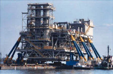
Offshore heavy lift system substitutes for large derrick bargesIn Lake Maracaibo, Venezuela, plans called for increasing production from an old field to 200,000 bpd from 10,000 bpd. A three-platform facility with secondary recovery equipment was designed. One platform contained waterflood equipment, a second platform was equipped with facilities to produce the low gravity oil, and the third was to hold compression equipment for reservoir pressure maintenance. However, a bridge with only 138 ft (42 m) of vertical clearance spans the entrance to the lake, preventing the mobilization of a derrick barge of sufficient size to set each platform deck in a single lift. Lift system solution. To substitute for a derrick barge, a unique lift system was devised by Versatruss of Belle Chasse, Louisiana. The system uses two barges, each fitted with three 70-ft, 48-in.-diameter A-frame booms, Fig. 1. The booms are connected to heel pins at the base, which enable them to rotate and to be raised and lowered. To eliminate boom tip motion caused by barge roll during system operation, the heel pins are positioned over the longitudinal centerline of the barge.
The booms have a specially designed connection at their tips, which mates to pins mounted in the platform deck structure. The six booms are operated by six 150-ton lifting winches, which are each paired with two 1,500-ton blocks, one 1,250-ton shackle and a 12-in.-diameter sling attached to a pad-eye on the deck leg. The lift system is positioned by maneuvering the two lift barges alongside the cargo barge, which supports the deck section. The booms are stabbed into the boom tip receiving pins, and the 12-in. slings are connected to the deck leg pad-eyes. The lift winches are engaged, and the two lift barges are pulled toward the transport barge, Fig. 2. As they draw together, the booms rotate on their heel pins, while the boom tips rotate on the pins mounted on the platform, thereby increasing the angle of the booms and raising the deck.
The deck, now suspended between the lift barges, is pulled over the jacket with auxiliary positioning winches. When the deck is in position over the jacket, it is lowered by the lift winches. The weight of the deck on the boom tips forces the booms down and the barges apart. The stabbing guides enter the jacket legs and lowering continues until the deck rests entirely on its jacket. The rigging is then disconnected from the platform and the barges are pulled away from the deck. Lift system details. The system was installed on two conventional 72-ft by 260-ft barges. Six A-frame boom sets were fabricated of readily available pipe sections, and the bottom of the booms were slipped into heel pin receiver cans. The specially designed tip was fitted onto the top of the booms, securing the A-frame. This feature allows the boom lengths to be changed for decks of different heights. The hydraulic hoisting winches are rated at 300,000 lb of single-line pull. The lower rigging, including blocks, slings and connecting pieces, utilized existing technology designed for the maximum expected loads. A sophisticated PLC control system synchronizes operation of the winches by implementing a control algorithm in real time, matching the operation of each winch. To produce the desired level of load control, each boom was instrumented with load-cell electronics, which transmits load readings to a central control console. The central control console was equipped with touch-screen MMI and other computerized monitoring of winch and engine functions. All lift data is transmitted via a data highway and, as a back up, data is simultaneously transmitted by radio. A single operator using one joystick performs the actual synchronized lift operation. For the initial hook-up of the lift barges to the deck, each barge was positioned about 20 ft from the deck using winch-positioning lines connected to the transport barge. The boom tips were then guided into the deck lifting pins. Next, winch lines with their rigging components were connected to the pad-eyes at the bottom of the deck legs. These pad-eyes, along with a lower horizontal structural member connecting the deck legs, became the lower tension chord of the system during lift. When hook-up was complete, the winches were engaged and lifting commenced. About 30% of the deck’s weight was shifted to the lift barges, leaving 70% of the weight on the transport barge. This load transfer produced a very stable "trimaran" configuration for towing to the installation site. After arriving on site, the transport barge was moored to the jacket with 75-ft mooring lines. Lines from an 80-ton winch located on each lift barge were connected to the jacket for positioning. The 150-ton lift winches were engaged, and the deck was lifted clear of the transport barge. The suspended deck was pulled over the jacket with the 80-ton winches and was slowly lowered into its final position. Technical and economic benefits. Transportation to the field may be arranged to coincide with the most favorable sea and weather conditions. Anchor systems are not required, and field installation – which includes positioning, ballasting (if required), setting and disconnecting of all devices – can be completed in six hours or less, minimizing offshore exposure. Transporting the deck in a trimaran or catamaran configuration produces a very stable system, which can withstand significant seas and adverse weather conditions. This was predicted by computer modeling and confirmed by operating experience. In areas such as the Caspian Sea, where access is restricted by water depth or limited clearances, the system is unequaled for its unique design and operational benefits. To reach such sites with large marine equipment requires shipping in small pieces and onsite assembly. The lift barges, with all equipment, can be moved through the narrow Volga canal system to the Caspian Sea. The capacity of the 6-boom system used in Lake Maracaibo is 7,500 tons, but an 8-boom system, using the same size components assembled on larger barges, could lift approximately 10,000 tons. To exceed this limit, it is merely a matter of increasing the size of the barges and lift system components. This system allows the loads to be controlled at all lift points. A test lift or pre-lift of a deck can be performed in protected waters to
validate all lift clearances and to develop the optimum ballast plan for the quickest possible installation
offshore.
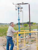
Wet-gas flowmeter maximizes reservoir recoveryInnovative, yet simple, multiphase flowmeter technology, developed by the U.S. DOE Idaho National Engineering and Environmental Laboratory (INEEL), is solving a challenging measurement problem in the oil and gas industry– accurate, cost-effective measurement of wet gas at the wellhead. Lockheed Martin Idaho Technologies Co. (LMITCO), INEEL’s managing contractor, licensed the technology last year to Perry Equipment Corp. (PECO), based in Mineral Wells, Texas. As part of LMITCO’s innovative technology transfer program, INEEL personnel worked under contract with PECO’s engineering staff after the licensing to refine the lab technology for commercial applications. The wet-gas flowmeter entered the market this fall. Theory of operation. The simplicity in the wet-gas meter’s design is because it is based on differential theory through an extended-throat venturi. Like most venturi flowmeters, it functions by accelerating flow through a constriction, then decelerating it in an expansion area. A pressure drop is measured in the constriction, which can then be related to mass flowrate of a single-phase fluid. Specifically, the product can be defined as an extended-throat venturi for measuring very high-void fraction (e 95% gas-to-liquid ratio) multi-phase flows. Because the liquid phase is denser than the gas phase, its equilibrium velocity appreciably lags that of the lighter gas. The innovation is in the extended throat that allows both flows to equilibrate, providing a predictable point of stability for each phase. The two phases are strongly coupled, resulting in pressure drops, across the constriction and in the extended throat area, that are significantly different than those experienced in single-phase flow. Information about the mass flowrates of each phase can be extracted from the measured pressure drops, Fig. 1.
Extended-throat venturi performance was evaluated under multi-phase conditions using natural gas and hydrocarbon liquids at 400 to 500 psi. Two hydrocarbon solvents were used as the test liquids: Isopar M (sp = 0.79) and Aromatic 100 (sp = 0.87). This data was compared to earlier air-water data taken at 15 psi. The high- and low-pressure data were consistent, confirming that size scaling of the extended-throat venturi was correctly represented. This consistency allows different-sized devices to be applied under different fluid conditions (temperature, pressure, gas and liquid-phase composition, etc.) with confidence. Application. The wet-gas flowmeter will fit directly on top of a wellhead (Fig. 2) taking continuous, real-time gas and liquid flow measurement as wet gas is produced through the measurement tube. It offers 2% repeatability, and accuracy of ±2–4% of total volume. The flowmeter is compact, allowing space savings for both onshore and offshore installations. The flowmeter is economical enough to be used on every wellhead all of the time.
Conclusion. The multiphase flowmeter
fills an industry void that addresses reliability of royalty payments at the wellhead. Producers can now have
continuous, reliable information to maximize gas recovery and improve reservoir management at a fraction of
the cost they now pay.
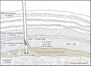
The Chunchula Challenge: A new fill up and cementing tool systemSpirit Energy’s Chunchula field in Alabama is notorious for its plastic, over-pressured salt strings found at about 18,000 ft. The salt strings are of particular concern, because the strength and constant shifting of plastic salts can cause severe damage to casing, essentially shearing it. The problem, therefore, is that when drilling, it is imperative that casing go beneath the salt strings to prevent losing the wellbore. A timesaving cementing tool, described here, helped the operator achieve its objective. Typical example. This is what Spirit Energy ’76 recently faced when the company planned to run 18,414 ft of 7-5/8-in. casing in an 8-1/2-in. directional hole. The challenge was to penetrate the threatening salt stringers found between 17,890 ft and 18,195 ft in Chunchula field. In a field without salt strings, a similar job – with no problems whatsoever – would take about 24 hours to run. However, this well was not a typical job, so Spirit asked Frank’s International & Frank’s Casing Crew to help find a solution that would save time, money and provide extra assurance that the casing would reach bottom at 18,390 ft.
Salt stringers were not the only obstacles to contend with in drilling this well. To have an economical well in a field like Chunchula, vertical drilling must be abandoned and more difficult and tedious drilling methods executed, such as lateral or horizontal drilling. Although horizontal drilling requires more precision, it offers greater return on a well, because more oil can be extracted. In preparation for this job, engineers at Spirit knew it was critical to have casing couplings at specific points in the 125-ft distance between the last salt stringers above the pay sand. Placing couplings in an exact spot was critical due to the plan to drill a lateral with a kick off at 18,220 ft, using a casing whipstock to build an angle to horizontal at 37.9°/100 ft. Considering the time constraints imposed by this exactness, Frank’s suggested that the company’s FACTS (Fill-up and Cementing Tool System) be used on this job. FACTS is the result of a joint-venture project between Frank’s International and Halliburton Energy Services. The tool combines Frank’s FC-1 Fill-up Tool and cementing adapter – with remote ball-dropping mechanism – with Halliburton’s Equalizer System and patented plugs. This patented combination eliminates large, cumbersome cementing heads and allows cementing operations to be actuated from the rig floor – including operating the balldrop head – since actuation of the plug dropping mechanism is performed by remote control. The system may be used with top drive or conventional rigs. With this system, fill-up, circulation and cementing are all performed through the same tool. This reduces the time needed to get the casing to its setting depth, as well as time needed for transitions from casing fill-up to circulating to cementing. Consequently, the risk of sticking the casing is minimized by using this tool. In essence, the system provides a safer, faster and cost-saving alternative to the drilling industry. At the 16-hour mark, 18,100 ft of casing had been run. With only 290 ft of openhole left above TD, the casing began to stick. In a matter of seconds, FACTS was activated from the rig floor and casing was washed down to TD – all within three hours. The safeness, simplicity and ease of the system become acutely obvious when comparing its performance to traditional methods of washing down casing. Typically, when casing sticks, the solution is to rig up a swage to allow circulating and washing down. This involves hoisting a worker into the air, up to the collar of the pipe. Once there, the worker then has to screw on a swage, which is cumbersome and weighs several hundred pounds. With the swage in place, lines and hoses are hooked up so that circulating material can be pumped in from the rig floor. This transition process, which must be repeated on all of the remaining joints of casing, is time consuming and potentially dangerous.
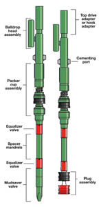
How the system works. The tool is connected to the top drive, while the lower end of the tool is inserted into the top casing joint. Cementing is performed directly through the tool. The top and bottom casing cementing plugs are released by weighted, plastic balls launched in the proper sequence from the unique ball-launch head. The FACTS plug set is designed with a top-plug, collet-releasing mechanism, which prevents launching the top plug prematurely. Two equalizer valves, inserted above the casing plugs, also prevent the plugs from releasing prematurely due to trapped pressure from above. Both the top and bottom casing cementing plugs are inserted into the top joint of casing before beginning cementing operations. This allows continuous cement pumping without shutting down to load the top plug in a plug container. Circulation is maintained during the entire cementing operation, providing better cement distribution in the annulus. No air is allowed to enter the casing string, which could lead to channeling of cement in the annulus. On this particular job, there were 10 remaining casing joints, which equates to a minimum transition time of three hours. Washing down the casing itself took three hours. Therefore, if a swage had been used, it would have increased the rig cost by six hours. More important, if a swage had been used, the result could have caused the casing to stick. Drilling Superintendent Nelson Emery is quick to support this, "If not for FACTS, casing would not have reached optimum depth, and revenue return on the well would not have been as great." After reaching TD, the well was conditioned using drilling fluid pumped at 9.2 bbl/min. at 2,500 psi. At this point, Spirit was able to proceed with the cementing job. With the new system, the cementing lines are already in place, thus making transition from circulating to cementing a matter of switching a valve. In conventional jobs, however, after circulation is completed, the swage is removed and the cementing head or plug container is rigged up, which entails more risk, time and money. Conclusion. Emery said, "This essentially saved Spirit $520,000, which is what it would have cost to transition the well to take vertical completion had TD not been reached." Emery continued, "When you realize the scope of that well, and what FACTS did . . . that is impressive. Without it, the future of this field would have been severely compromised." With the new technique, there is no downtime nor risk to anyone: just activate
the cementing from the rig floor. Encouraged by the success of this recent job, the test system is scheduled
to be used on several upcoming wells by several industry majors.
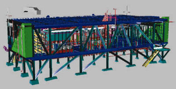
3-D software reduces design time for offshore drilling systemIvan Curiel, President, Power Man-agement Inc., New Orleans, Louisiana Transocean Offshore of Houston, Texas, specializes in technically demanding segments of the offshore drilling business such as deepwater and harsh-environment drilling services. Transocean recently completed construction of one of three new, technologically advanced drilling ships designed for 10,000-ft deep water and a drilling depth of 35,000 ft. These ships, Discoverer Enterprise, Discoverer Spirit, and Discoverer Deep Seas, are dynamically positioned drillships. The ships feature a new and unique well-construction methodology developed by Transocean. It improves drilling efficiency by allowing both drilling and pipe assembly to take place simultaneously. By using 3-D plant modeling software, Power Management Inc. completed the design and documentation of the world’s deepest offshore drilling system in about 23,000 hours, an estimated 17,000 hours less than if the project had been done with 2-D CAD. By creating a 3-D model of the topside system, engineers were able to get feedback early from Transocean Offshore. This allowed them to incorporate the customer’s changes sooner and saved many hours of rework. Topside design. The contract called for the design of all topside equipment, including substructure, drill floor, BOP module and all interconnects. On a previous project involving an oil and gas production system, engineers had used 2-D CAD to lay out all system components and generate drawings. However, they found it difficult to communicate their designs to the customer using 2-D drawings, e.g., a fake floor above the pipes that was difficult for the customer to visualize on the drawings. It was often necessary to revise the design to change features that the customer had not understood when initially looking at the drawings. Another drawback to working in 2-D was the difficulty of detecting interfering objects. To overcome 2-D design limitations, engineers decided to do the Transocean project in 3-D. The software they used was AutoPLANT 97 from Rebis, Walnut Creek, California. This software runs as an add-on to AutoCAD, which was attractive since many clients use this program. Customers can take AutoPLANT drawings and edit them with plain AutoCAD rather than having to use a specific plant-design program. In addition, the software sells for about one-third the cost of other workstation-based plant design systems, yet provides all the necessary functionality. Another attractive feature was the ability to buy only the needed modules, unlike other plant-design products, where it is necessary to buy the complete system. To start the project, the topside of the Transocean drillship was divided into three separate sections. This way, each section could be drawn in parts and assembled on the ground while the ship’s hull was being built in Spain. The first step in assembling a 3-D model of the drilling system was creating digital models of all components. This was done using the software’s Equipment Module, which automates the modeling process by providing a library of parametrically defined components. With this library, a designer simply enters a few values representing the equipment specifications, and the software draws the model. For example, the designers got equipment specifications either from manufacturers’ catalogs or from AutoCAD drawings supplied by the manufacturers. Then, to create an AutoPLANT model of a pump, they chose a pump from the software’s equipment library, typed in a few dimensions representing the manufacturer’s specifications such as height of the suction and discharge flanges, and the software automatically created the pump model with the flanges in the correct locations.
Single-model benefits. After placing equipment in the AutoPLANT model, the steel framing structures, pipe racks and supports were modeled using the software’s Multi-Steel Modeler. This module provides the functionality needed to place 3-D structural steel, including drawing setup and creation, 3-D grid placement, steel placement, database management, steel editing, display options, steel annotation and access-way (stairs, ladders, platforms, handrails) placement. Similar to the Equipment Module, the Multi-Steel Modeler has a library of standard shapes. When a designer wanted to run a beam, he simply chose the beam shape he wanted and indicated the desired location. The software drew the 3-D beam model automatically. As this work was being done, piping designers were using the software’s Piping Module to route pipes in 3-D. They found working in 3-D to be much better than working in 2-D, because they could see the impact of their work immediately, rather than flipping through 2-D drawings and trying to follow the entire line. At this time, electrical designers were using the software to route electrical trays. Because all the different design disciplines were contributing to the creation of the entire system’s 3-D model, interferences were avoided as the initial design work was going on. For example, when electrical designers routed trays, they could see the location of pipe racks and work around them. This was a big improvement over working in 2-D, where electrical designers worked from steel background drawings that typically were not up to date. Another way that interferences were prevented was by using the Explorer/Interference Detection module. As designers navigated through the model, they could look at the layout from any angle to spot interferences that they might not have seen when they first created the design. The software recognized all one, two and 3-D AutoCAD entities for viewing and interference detection; these included lines, polylines, 2-D surfaces, meshes, 3-D faces, ACIS solids and blocks, as well as any custom 3-D objects created. This module was also helpful for determining the suitability of certain design decisions, e.g., whether there was sufficient access to equipment or whether a valve was too high to reach. The walkthroughs were recorded and turned into movies as another design-evaluation tool. Faster documentation. The software generated drawings automatically from the 3-D model, which facilitated the required project documentation. Timesavings were most evident during production of isometric drawings; an automatic isometric-generation program, called ISOGEN, was used. Rather than needing four hours to produce an isometric drawing from scratch, ISOGEN created them in minutes directly from the 3-D model. Only about 30 minutes were needed to check each drawing and make minor changes. The Transocean project required 1,100 isometrics, so nearly 4,000 hours of drawing time were eliminated. The company saw additional timesavings when producing the project’s bill of materials. The software keeps track of all materials used in the model, and when finished, the program prints out a list of all items. This was faster and more accurate than searching through drawings and counting materials. It also made it possible to give Transocean the information before producing any drawings. Summary. In addition to saving time, creating a 3-D model resulted in a better overall design. With the enhanced visualization provided by the software, designers were able to do a better job of piping and placing equipment, particularly in confined areas. They could see the space they had to work in well enough to compress the equipment and pipes, fitting three pipes into an area where they might have only put two had they worked in 2-D. Although this did not decrease the overall size of the drilling system, it did help design better equipment access. For Transocean Offshore, working on this project in 3-D had many positive
results. It gave them a set of clash-free drawings that were available sooner than they would have been if
only 2-D had been used. It gave them an accurate bill-of-materials report much quicker as well, which allowed
the company to avoid construction delays due to untimely delivery of materials. Most important, it provided
the time and tools needed to optimize drilling system design, allowing the drillship to perform reliably in
demanding deepwater conditions.
Copyright © 1999 World
Oil |