RSS design aimed at a growing scope of directional drilling demands
Rotary steerable systems (RSS) are typically based on technology developed in the last century. Modern directional drilling demands a very different ethos and approach to the tool’s design. Today, RSS are used in a much broader spectrum of the market than was the case in previous decades. No longer a niche product, rotary steerables now account for more than half of the directional drilling market, both in the U.S. and globally.
DESIGN CONSIDERATIONS
When Weatherford began developing the Magnus RSS in 2016, it identified a broad scope of key capabilities. The new tool had to be capable of being deployed anywhere in the world, which implied a simple approach to repair and maintenance without the need for specialized facilities, test rigs or flow loops, allowing tools to be repaired local to operations. If the tools had to be shipped to a central location for repair, this would significantly impact utilization, itself a key driver for cost-effectiveness in rotary steering. The new tool would also have to be simple to train people on, to accelerate learning in more remote locations and also counter a shortage of experience following the mass industry layoffs since 2014.
The rotary steerable market has changed in another way. In the early years of rotary steering, tools were usually driven directly from surface. Now, many rotary steerable runs are below a positive displacement downhole motor—so called “motorized” applications. Any new tool needs to be capable of operating below a motor and must be able to cope with not only the higher rotary speed but also the high torque outputs of new generations of increasingly powerful motors.
Perhaps more important, was the wellbore quality and management of tortuosity that would become paramount in the coming years. Several existing rotary steerables mimicked directional motor drilling, in that they divided time between steering (with a motor, think sliding) and drilling with zero effective bias (with a motor, think rotating) to achieve an average dogleg across a section. Although the average dogleg achieved this way looks acceptable on a survey report, this process introduces micro doglegs and sections of high tortuosity. These, in turn, cause drilling problems and, once the well is drilled, can lead to significant problems with completing and producing the well. The tendency toward drilling increasingly longer lateral sections exacerbates this problem, meaning that a tool for future decades must be capable of drilling perfectly straight and of drilling a perfectly smooth curve of any curvature, up to the tool’s maximum capability, when called on to do so, Fig 1.
These requirements were distilled into specifications that drove the development of what became the Magnus RSS. The design team was then challenged to deliver a working tool and begin drilling tests within a year of the project kick-off.
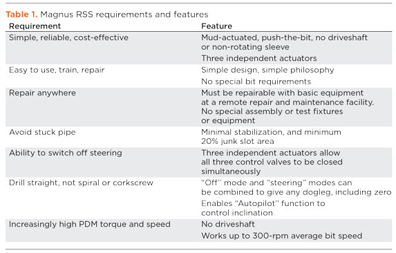
The requirements mandated a very clear direction for the new RSS development and the design’s associated technical features, Table 1.
IMPLEMENTING THE CONCEPT
To achieve being simple to repair and use, and capable of repair at remote locations at minimum cost, a minimalistic approach to design was taken, using as few parts as possible in constructing the tool. Many existing rotary steerable tools, including some so-called “push-the-bit” and almost all “point-the-bit” tools, use a non-rotating sleeve, with a driveshaft running through the center to provide power to the drill bit. Any non-rotating sleeve makes a tool more complex to assemble and repair, more expensive to operate, less capable of torque transmission (the shaft diameter is necessarily smaller) and less slick, with a smaller junk slot area, and thus more prone to sticking.
Push-the-bit operation. For these reasons, point-the-bit operation was rejected, and a push-the-bit tool, where all parts on the outside of the tool rotate, was selected. Additionally, to reduce parts count and make repair as simple as possible, drilling mud actuation was preferred over oil actuation for the steering mechanism.
During controlled field trials, the tool has proven simple to maintain, with key wear and erosion parts replaced at the test site in just a few hours. All that was available in the workshop used for these repairs was a break-out machine, a crane, and a tool chest. This allows the tool to be repaired close to the action, regardless of where it is deployed, significantly increasing utilization and asset availability, and allowing for in-country repair or even in-country manufacture.

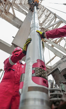
The tool’s exterior uses three steering pads, between 1 and 2 ft from the bit, to selectively push the bit sideways, Fig. 2. Any drill bit used with push-the-bit rotary steerables can be utilized; there is no need for a special bit. These pads, together with a stabilizer about 11 ft from the bit, create a three-point geometry that defines the tool’s dogleg capability.
To address the requirement for infinite resolution of steering bias, to drill a smooth wellbore, and to allow the tool to be “switched off” for operations where steering bias is undesirable (for example, drilling out of casing), each of these steering pads is independently controlled. To provide a constant bias in one direction—for example, to build or turn the well—the pads are extended individually, each at the same orientation and once per revolution. To drill with no bias, the pads are starved of drilling mud and do not extend. By combining zero and maximum bias on a short duty cycle, anything between zero and maximum bias can be achieved, and with effectively infinite potential resolution. In addition to providing optimal directional control, having three independently controlled pads also creates some redundancy. If one of the pad assemblies were to fail, the other two would be unaffected, and the tool could continue drilling a trajectory in most cases—in the same way that an airliner can complete its journey in the unfortunate event that one engine fails.
The steering pads are extended by drilling mud under pressure. The pressure comes from a differential between the bore of the tool and the annulus, and mud is ported to the steering pads by three rotary vales, one for each pad. To extend the pad at a given toolface and steer the well, the valves are held non-rotating in space as the tool rotates around them. Thus, they must be able to rotate backwards at the same speed that the bit rotates forwards, up to the specified maximum of 300 rpm and in the presence of instantaneous variations of rotary speed, due to stick-slip. This is achieved by a state-of-the-art control system that includes a rate gyro to measure instantaneous bit rotary speed.
Commands, including toolface and effective bias percentage, and “off” mode or inclination hold, where the tool will automatically seek out and/or hold a given inclination, can be downlinked from the surface, as with existing rotary steerable tools, by sending pressure pulses in the mud flowing into the well. The RSS tool is capable of interfacing with existing MWD and LWD tools to add additional measurement capability and to provide a conduit for information to the surface.
TESTING AND FIELD VALIDATION
Nine months of controlled field-testing in 8-in. hole followed development of the 6.75-in. version of the Magnus tool. In these privately funded tests, the development team was able to shake out bugs and introduce simple improvements in mechanical design and control, while demonstrating build, drop and turn of the tool at doglegs up to 12°/100 ft and rotary speeds up to 260 rpm. Also demonstrated were the ability to kick off from a cement plug and drill vertical sections, tangents and laterals in inclination hold mode. To conclude testing of the 6.75-in. tool at the controlled field test facility, a complete vertical, curve and lateral well were drilled, including a turn section in the lateral. The lateral was drilled in a single run with the tool in motorized mode, below a straight hole, positive displacement motor. Subsequently, a 9.5-in. version drilled a 12¼-in. well in a single run to include a vertical section, build at 6°/100 ft, and tangent hold.
Since controlled field tests were completed, the Magnus tool has drilled over 200,000 ft in commercial wells in the U.S., Latin America and the Middle East.
Texas results. More than half of this footage has been achieved in the Permian basin, drilling multiple formations in the Midland and Delaware basins, including Wolfcamp A, Wolfcamp B, Wolfcamp E, Bone Springs, Spraberry and Woodford. Performance has proven consistently economical when compared with motor drilling, increasing ROP over 400% in some applications. The RSS also eliminated expensive BHA agitation tools and improved hole quality and tripping time. In the Permian, the tool has repeatedly reached TD in long, 2-mi. laterals.
Another quarter of the footage drilled to date has been in the Eagle Ford shale of South Texas, where the new tool has replaced existing point-the-bit rotary steerable systems while improving penetration rates over both motor drilling and point-the-bit RSS by at least 50%. Bearing out the results of the market research that drove tool specifications, over 85% of runs in the U.S. have been motorized applications, where the bit rotary speed was 200 rpm or more.
The Magnus RSS also has seen successful service in multiple Latin American applications, where it has demonstrated fine directional control, in addition to reliability and cost-effectiveness. Latin America saw the first application of the RSS on a hole enlargement-while-drilling (HEWD) application. This re-entry application required setting a whipstock in the 9 ⅝-in. casing, milling a window and then exiting the window to drill the 8 ½-in. intermediate section. It was necessary to enlarge the hole, to provide clearance required for running 7-in. casing. Here, the RSS was used with a Weatherford RipTide drilling reamer and HEL LWD system with resistivity measurements. The well was drilled successfully and steered in 8½-in. hole while simultaneously enlarging it to 9⅞-in.
The first offshore run with the new RSS also took place in Latin America. Here, the requirement was to drill a production well, using a 6 ¾-in. rotary steerable to drill 8 ½-in. hole, with HEL LWD, while displacing an existing rotary steerable and drilling the well with fewer stabilizers in the BHA.
Multiple key performance indicators were set and achieved for this milestone application, which was drilled in a single run. Requirements for directional control were strict, and required maintaining the well trajectory with maximum dogleg below 3.8°/100 ft to minimize borehole tortuosity and maintain good wellbore quality. The tool’s proportional control system was able to meet this requirement, with maximum recorded dogleg of 3.7°/100 ft.
A requirement of a maximum 16.4 ft distance to plan at total depth also was achieved. Maximum distance to plan at any point was 10.7 ft. ROP benchmarks, set using existing rotary steerables, were exceeded: the average on-bottom ROP was stipulated to be not less than 30 fph, and the tool achieved 55 fph. The time programmed to drill the 8½-in. section was 429 operating hours, and it was drilled in 133 operating hours, an improvement of 222% and a saving of more than 12 days or $1.6 million resulting from more efficient drilling.
In its first Middle East application, the Magnus tool drilled a successful 8½-in. curve section, kicking off from vertical and drilling to landing point in a single run through challenging interbedded limestone and anhydrite formations. Severe levels of stick-slip had to be overcome through almost all the section. In line with a key customer requirement, the tool was retrieved with minimal pumping or back-reaming. The RSS is currently deployed in three Middle East countries.
CONCLUSION
In the past two years, the Magnus RSS has been developed, tested and brought to market. It builds on decades of industry experience using RSS and the progression of the technology from niche to mainstream. To fulfill the needs of a post-2014 directional drilling industry, the tool combines the necessary directional steering functionality with wellbore quality, drilling and tripping efficiency, and asset availability. These capabilities have been proven in applications in the U.S., Latin America and the Middle East. ![]()
- Coiled tubing drilling’s role in the energy transition (March 2024)
- Shale technology: Bayesian variable pressure decline-curve analysis for shale gas wells (March 2024)
- Oil and gas in the Capitals (February 2024)
- Digital tool kit enhances real-time decision-making to improve drilling efficiency and performance (February 2024)
- E&P outside the U.S. maintains a disciplined pace (February 2024)
- U.S. operators reduce activity as crude prices plunge (February 2024)

