Pre-pressurization technique expanding application of flexible flowlines into deepwater environments
Compared to rigid steel pipes, flexible pipes consist of different layers of various materials that act together, enabling unique mobility behavior. This has facilitated the development of several fields and subsea tie-backs that would have been economically and technically unfeasible with rigid pipes, due to the requirement for extensive seabed preparations and a costly construction campaign.

Bonded and unbonded flexibles. A bonded flexible pipe consists of an elastomeric matrix, reinforced with several armoring layers to give the pipe the required strength. The armoring layers are bonded and fully encapsulated by the elastomer and are used mainly for offloading hoses, as well as some drilling applications. While an unbonded flexible pipe also consists of several layers, each layer has a specific primary function, Fig. 1.
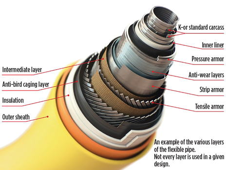
- Internal carcass—for prevention of collapse
- Internal liner—primarily an internal fluid barrier
- Pressure armor wires—provides pressure containment
- Tensile armor wires—sustaining tensile loads and internal pressure
- Outer sheath—resists mechanical damage and prevents seawater ingress.
Additional layers can be included in a flexible cross-section, to serve specific functions. For example, insulation, anti-wear, or enhancing relative friction between layers. This enables flexible pipes to be tailored to suit customized design requirements.
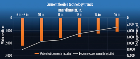
The current application of flexibles ranges from 2-in. to 20-in. ID, with typical U-values ranging between 2 W and 15 W/m2k and pressure containment up to 20,000 psi for various applications. Figure 2 shows typical trends of design pressure, water depth and ID for currently installed flexibles (both flowlines and riser applications).
Another trait of flexible pipes is their ability to relax the bending moments at certain curvature over time, due to the shake-down of friction between the polymer layers. As a result, the flexible can reset its frictional property and regain a “pre-slip” type of behavior over time while maintaining inelastic deformation. The degree of such frictional gain/reset will depend on the level of polymer layers relaxation. Hence, a hysteresis type of behavior can be modelled in the flexible pipes with a certain degree of caution to the frictional component regained, due to relaxation of the polymer layers over time.
BUCKLING BEHAVIOR
Due to the composite nature of flexible pipes, they generally exhibit a relatively high axial stiffness and low nonlinear bending stiffness, which depends on the following factors: 1) cross-section design; 2) pipe curvatures; 3) bore temperature/pressure; 4) external ambient temperature; and 5) wall status being in tension or compression.
Any variation in the above listed parameters will impact the flexible mechanical properties, which pose a challenge to model correctly. There is currently no readily available FE software that includes the effect of such parameters and is geared for in-place analysis of unbonded flexibles.
Due to their low bending stiffness, flexibles are prone to buckling at a lower compressive, effective axial force. When compared to rigid pipeline, they are also more sensitive to the shape and size of seabed imperfections and, therefore, normally not straight after laying. Such behaviors have made accurate modeling of flexible pipeline challenging.
Flowline movement under operational conditions is dependent on the presence of restraints surrounding the pipe and defines the path of least resistance. Typically, all flexible flowlines in fishable waters are trenched, and buried or covered on the seabed, if trenching is not considered feasible. Depending on the geometry of the trench and the depth of cover above the flowline, such embedded flowlines tend to behave in a mixture of lateral and vertical movements.
While most local mechanical design is undertaken by flexible manufacturers and design houses, it is essential to assess the global buckling behavior of the flexible under different loading conditions. This should include high-level in-place assessments, such as routing, on-bottom stability, on-bottom roughness, global buckling and global fatigue checks.
Normally, an integral part of the in-place design of flexible flowlines is to ensure that there is adequate overburden above the lines to restrain excessive vertical movement during operation, known as upheaval buckling (UHB). This can lead to two main risks:
- Vulnerability to environmental or physical hazards, such as snagging, associated with positive vertical elevation above the seabed.
- Loss of structural integrity, due to potential localization of vertical movement, leading to excessive local curvature potentially exceeding the specified minimum bend radius.
The design considerations for flexible UHB mitigation, include:
- Capturing the shape of flexible to a good accuracy—enabling correct effective axial force (EAF) evaluation.
- The use of the adequate moment-curvature relationship—various design load cases.
- Design safety factors and structural reliability assessment —applicability of code approach.
- Decouple the axial and bending response of flexible pipes —non-linear moment curvature response.
UHB mitigation design also may extend beyond overburden specification to include flowline route optimization, installation of mid-line expansion loops, or pressurizing the lines prior to backfilling.
Several design and installation advances have been made to reduce the buckling propensity and overburden requirements. This analysis should determine the flowline lateral and upheaval response and the associated integrity implications under installation, pressurization, depressurization, and operation cycles, while also accounting for the change in geotechnical parameters, due to trenching/backfilling and/or rock dumping.
Due to the very nature of the flexibles, the analysis should also account for the non-linear behavior in the FE modeling of the flexible to calibrate the initial pipe shape and mimic the variation in bending stiffness, temperature and pressure expansion coefficients, and driving force under pressurization.
Over the last three decades, several analysis models have been developed for upheaval buckling analysis. These approaches have focused largely on rigid pipeline systems, which are more widely used for oil and gas applications, particularly where trenching and backfilling are common practice, and are relatively simpler design.
CASE STUDY
In 2016, to reinstate two existing wells to recover stranded reserves, a major operator commissioned Xodus to perform in-place design for a new flexible flowline. The objective was to replace 5.2 km of existing decommissioned 6-in. rigid carbon steel pipeline between the manifold and the isolation valve skid.
In the North Sea, flowlines with OD less than 16-in. are required to be trenched and buried for protection. Therefore, predictive UHB at the detailed design stage was followed by an out-of-straightness (OOS) analysis, post-installation, to establish the soil cover and determine additional overburden requirements. As empirical approaches are not suited to capture non-linear flexible behavior, both analyses were conducted using a FE approach to avoid either over-or underestimation of download.
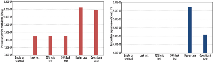
A range of load cases is typically considered for flexible UHB design to capture all potential pressure and temperature combinations. The non-linear behavior of flexible polymer layers and their interaction with steel layers drives the variation of flexible properties with pressure/temperature and loading direction.
Although the increase in pressure shows limited effect on pressure expansion co-efficient, it has a more significant effect on the pre-slip bending stiffness value. This is mainly due to the internal pressure increasing the friction between the layers, causing a stiffening effect. Conversely, an increase in temperature will result in an increase in temperature and pressure expansion co-efficient and reduction in post-slip stiffness. The reduction of post-slip bending stiffness is driven mainly by the mechanical properties of polymer layers with the increased temperature, Fig. 3.
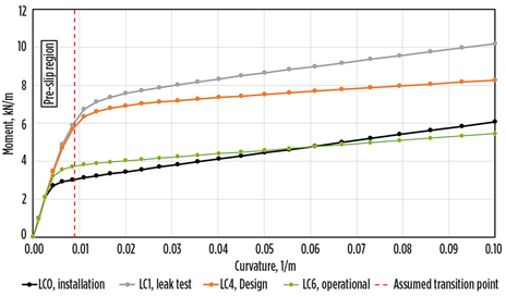
The moment-curvature relationship shows the transition between post-slip and pre-slip regions, Fig. 4. It is evident that the transition curvature between the pre-slip region and the post-slip region increases with pressure and decreases with temperature, meaning that a pressurized flexible will have higher bending stiffness than an unpressurized flexible, when bent to the same curvature.
An effective method that can be used to mitigate UHB for a flexible, and avoid excessive the rock dumping requirement, is to pressurize-up the flexible, trench the flexible during pressurization, depressurize while the flexible is in the trench to lock some tension in the wall force, and hence reduce the buckling potential when the flowline is in operation.
The fully restrained, compressive effective axial force in the flexible flowline is dependent on several parameters, such as wall status (either tension or compression), bore internal and external temperature and pressure. The fully restrained compressive effective axial force is typically calculated as follows:
F e f f = −(ap ΔP + aT ΔT) EA
Where:
F e f f = Effective axial compressive force in the flowline
ap = Equivalent system pressure expansion coefficient
aT = Equivalent system thermal expansion coefficient
EA = Equivalent system axial stiffness
ΔP = Differential pressure
ΔT = Differential temperature
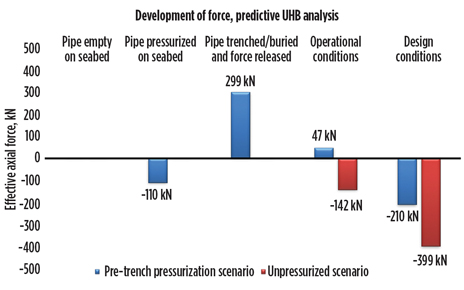
The wall status is defined by the true wall force value, Fig. 5. Fundamentally, under operational conditions, the fully restrained compressive axial force consists of compressive end cap force and the true wall force. The value of the compressive end cap force, in relation to the calculated compressive effective axial force above, defines the value (+ve or -ve) of the true wall force which subsequently defines the wall status (tension or compression). The net effective axial force used for the UHB analysis is quantified as follows:
- The residual compressive effective axial force in the flowline following pressurization and laterally moving on the seabed.
- Following trenching and backfilling, the release of pressure at laterally mobilized location results in development of locked-in tension.
- The net positive tension is calculated by subtracting the residual compressive axial force from the effective axial tension following depressurization.
- The net positive tension is then deducted from the effective compressive axial force under design/operational conditions. The calculation of the net compressive axial force accounts for the change in wall status, as the flowline alternates between compression and tension.
Flexible flowlines are generally installed with low touchdown tension and subsequently low residual lay tension. Ignoring such tension yields conservative results for UHB analysis. It is also expected that the process of pressurization on the seabed will relieve any residual tension in the flowline and will subsequently result in lateral/vertical movement to relief the generated compressive effective axial force
A lateral buckling assessment is important during the predictive stage to estimate the residual compressive effective axial force at buckled sections. The value of residual force will contribute into the value of locked-in tension. This also considers non-linear flexible properties and adequate soil modeling.
The trenching of the flowline is performed under pressure, whereby a range of typical imperfections is assessed, representing possible curvatures attained during trenching. Such defects are selected to identify upper and lower bound buckling propensity and to investigate the effect of pressurization on rock quantity. The idealized imperfection shapes are dictated by pressurized bending stiffness with wavelength factor applied to reflect anticipated as-laid curvatures resulting from trenching soils in the area.
PREDICTIVE UHB ANALYSIS
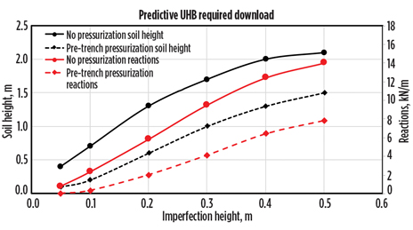
Comprehensive studies showed that pre-trench pressurization reduces required download by an average 50%. As an example, for a maximum anticipated imperfection (0.5 m), 1.5 m of soil cover is required if pre-trench pressurization is adopted versus 2.1 m, if the flowline is trenched then leak tested, Fig. 6. Analysis concluded that a combination of pre-trench pressurization, combined with an increase in depth of cover, will minimize or even eliminate rock dump post-backfill.
OSS ANALYSIS
The flowline was installed, pressurized on the seabed to 1.1 x Design Pressure (242 barg) and jet-trenched prior to tie-in of the flowline ends. A post-lay survey was performed prior to trenching while the flowline was kept pressurized, and a post-trench survey was conducted before depressurization.
As there was no as-laid survey performed during the OOS stage, Xodus had to understand the relation between the mobilized seabed shape and residual effective axial force in the flowline following pressurization. Therefore, several lateral buckling analyses, covering a range of imperfections and soil axial/lateral resistance combinations, were performed to interpret a robust relationship between the as-surveyed curvature and the residual effective axial force.
A matrix of load cases also was developed, using historic data for similar flexible developments, which were surveyed post-lay and actual curvatures (both axially and laterally) interpreted. Due to the difference in flexible properties between the historic data and the line data, three sets of data were used. They represent the low, average and high lateral imperfection frequencies and for upper, best and lower bounds soil properties, respectively, Fig. 7.
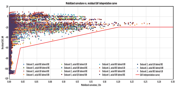
The results were amalgamated, and a conservative relation between the analysis’ mobilized curvatures and the residual effective axial force was established. The EAF interpretation curve is then adopted to estimate the residual effective axial force in the flowline following pressurization and trenching. The force at the peak of each mobilized curvature is identified, and an average soil friction is considered to develop the force build-up profile between consecutive imperfections.
Flowline trenching and backfilling were performed under pressure, and an as-backfilled survey also was conducted. The predictive UHB recommendation was to try and achieve the best depth of cover, possible, by focusing on the trenching operation. As a result, an average depth of cover of 1.4 m was achieved which, when viewed with pressurized results, indicated that it was likely that the flowline would not require any additional rock.
Moreover, the imperfection statistics from the as-trenched survey showed that the majority of in-site vertical imperfections have lower curvatures/heights than anticipated in predictive UHB. This is due fundamentally to the emphasis on pipeline trenching performance to maximize depth of lowering and minimize trenching-dominated imperfections.
Following the depressurization cycle, there is a potential for the flowline to move laterally/vertically, as tension develops as an attempt from the flowline to straighten out to its original (pre-pressurization) shape. This “relaxation” behavior is however, restricted by trench wall lateral capacity, a subsequent function of backfill cover height and soil properties. This has been accounted for during FE analysis, to anticipate further reduction in locked-in tension prior to the application of design pressure and temperature.
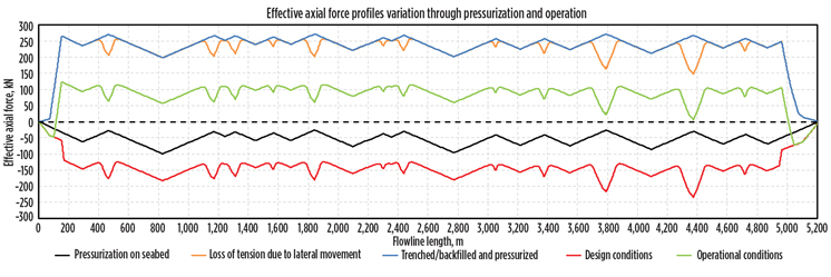
The final effective axial force under design conditions was then calculated to include the cycling effect in the pipeline. The calculation considered the variation in flexible properties, due to temperature and pressure, while also accounting for wall status. The pressurization resulted in an average reduction of 40% in design case effective axial force. The soil download provided from the depth of cover showed that most of the line is not susceptible to upheaval movement for both cases, aside from one location where pre-trench pressurization was key to avoiding further intervention. The change in effective axial force through installation sequence is presented in Fig. 8.
Results showed that, based on the soil backfill cover achieved, there was no additional mitigation required for the flowline, thanks to three main drivers: 1) achieved depth of cover was higher than anticipated; 2) in-situ vertical curvatures are lower than those anticipated during predictive design; and 3) pressurization of flexibles significantly lowered net effective axial force leading to reduced reactions.
CONCLUSION
The design and material selection of flexible lines have seen a vast improvement in technology over the past two decades. This has led to flexibles being more versatile for deeper waters (up to 3,000 m); harsher environments where waves, currents plus vessel motions pose substantial challenges to fatigue life; and more onerous operational conditions.
Pre-pressurization of flexibles is an effective, robust method of global buckling mitigation. It results in locking tension in the flexible which effectively reduces the net compressive axial force in the system during operation.
The Xodus project has demonstrated that it is possible to develop an affordable and fit-for-purpose solution to recover trapped reserves from late-life assets. In 2017, the field was successfully reinstated with no safety incidents, and the project delivered two weeks ahead of schedule and around 18% under budget.
Since the restart, the field has been producing up to 20% better than originally anticipated ,and has been a catalyst for the operator to redevelop and reinstate other satellite fields that have stranded reserves. WO
- Subsea technology- Corrosion monitoring: From failure to success (February 2024)
- X80 heavy wall pipe solutions for deep/ultra-deepwater field developments in mild sour environment (November 2023)
- FluiDeep: An innovative subsea storage and injection solution for chemicals management (November 2023)
- Wellbore seal control and monitoring enhance deepwater MPD operations (October 2023)
- Novel approaches to deepwater steel catenary production riser life extension benefit ESG (September 2023)
- Simplifying testing on subsea umbilical installation campaigns (August 2023)

