Digital twin technology lowers offshore inspection costs
Mobile offshore drilling units (MODUs) feature a conduit between the drilling rig and well system—the drilling riser. This critical component typically comprises a series of connected 75-ft to 90-ft-long riser joints. The riser is the main conduit to drill through, connecting to the top of the BOP, which is latched to the wellhead and casing system on the seafloor. Failures of these drilling riser systems can be serious occurrences, causing the uncontrolled release of synthetic, oil-based muds and cuttings into the environment.
Furthermore, if a failure of a drilling riser system were to occur over existing subsea architecture, the pollution impact could be devastating. It is, therefore, in the best interests of all stakeholders to develop a full understanding of riser system usage, to ensure that all riser damage and associated risks are captured and quantified accurately, based on past loading history and any future loading scenarios.
COST OF COMPLEX LOGISTICS
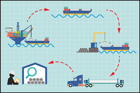
The riser system experiences significant wear, erosion, corrosion, fatigue damage, and seal damage during the course of its operations. To track this deterioration over time, drilling riser joints are typically inspected at five-year intervals. This is usually accomplished by rotating 20% of the riser joints onshore every year, to be disassembled and inspected. A large number of costly and time-consuming boat trips from the MODU to onshore facilities are required for this procedure, in addition to trucking of the riser to the inspection facility once onshore, Fig. 1. Approximately 20 riser joints at a time from each riser system are transported by boat and one riser per truck to the inspection facility each year, making the logistics of performing a drilling riser joint inspection complex and costly.
Since drilling riser joints may not be in continual use, it makes sense that maintenance periods should be usage- or condition-based instead of calendar-based. Classification societies ABS and DNV accommodate this alternative approach by calling for the owner of the drilling riser to maintain a preventive maintenance program, to manage the riser integrity. Such condition-based maintenance (CBM) programs that involve an approved condition monitoring plan and onboard/onsite inspection can provide tangible benefits. Programs, such as CBM and risk-based inspection (RBI), help adjust inspection scope and frequencies to optimize integrity management, based on the actual condition of the riser and its components.
INFORMED DECISIONS
A laser-based measurement for inspection, together with monitoring of riser systems, has been implemented with a new standard process for collecting critical riser data, which is ABS-approved. The aim is to mitigate the costs and time associated with essential MODU drilling riser inspections, by empowering drilling contractors to reliably determine the condition of drilling riser joints, consistently predict when vital components will require service, and accurately assess remaining component life. The approach utilizes a life cycle condition- based monitoring, maintenance and inspection system that can be deployed on a MODU, enabling resources to be deployed only when necessary. The solution consists of: 1) performing a baseline inspection on the riser joints to assess their present state; 2) collecting the environmental and operating data when the rig is on site drilling; and 3) feeding the environmental and operating data into a digital twin.
The technology involved in this process is unique. There is no alternative technology that brings together a digital twin of the riser system, onboard riser inspection and load monitoring of the riser to calibrate the digital twin, followed by a determination of actual loading, stresses and fatigue damage over each riser joint, thus accurately assessing remaining life and allowing targeted inspection. The technology can be used as a forward predictor to determine when riser joints may be susceptible to damage.
MONITORING/INSPECTION OVERVIEW
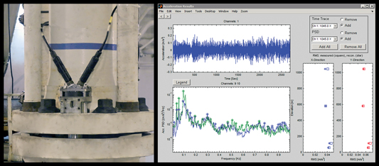
The drilling information, metocean conditions and riser data are collected to determine riser joint fatigue damage. The proprietary system determines stress and fatigue at any location in a riser system/wellhead/conductor casing via measurements from several accelerometers and angular rate sensors placed at strategic locations along the riser (Fig. 2), together with analytical riser mode-shape information. Because the only required online inputs are the dynamic riser response, top tension and mud weight, fatigue can be estimated without knowledge of the impinging currents or other forcing events.
Vibration sensors and data-acquisition electronics are housed in the subsea vibration logger (SVDL), which is ABS-approved. The data are then processed using patented technology that integrates a computer algorithm to synthesize stress estimates along the entire riser length, using a database of riser dynamic modes. The estimates are then processed chronologically via rain flow counting to determine fatigue damage accumulated during a drilling riser campaign, thereby providing actionable information to the drilling crew.
DATA CAPTURE PROCESS
Detailed measurements are collected, including vessel, metocean, drilling conditions and either real-time or stored load measurements during the drilling operation on the riser system, using SVDL technology to assess fatigue damage. A laser profilometry system is used to collect measurements on the inner diameter of the main bore and auxiliary lines, between wells to characterize the state of drilling riser joints. The SVDL can be installed individually by an ROV on riser joints, wellheads and BOPs in an “offline” mode. In the offline mode, the recorded vibration data are retrieved after the measurement campaign and then processed offline to estimate stress and fatigue. A semi-analytical method is used to estimate wellhead fatigue damage directly, using the measured BOP stack motion data.
Analytical transfer functions are used to directly compute stress time histories and fatigue damage at any location of interest in the drilling riser system. The offline fatigue monitoring system provides the operator with a useful tool to assess system integrity at any time during a drilling campaign. The semi-analytical method to compute fatigue from measured vibration provides rapid turnaround of raw data to fatigue consumption, enabling informed decisions to be made in adverse conditions.
After the drilling riser joints have been recovered to the surface, laser profilometry is used to inspect them. The laser ID inspection consists of deploying the system (specifically modified for drilling riser applications) through the ID of the riser via a tethered crawler. The scan starts in the launch tube and travels down the entire riser tube taking measurements. The scanner head rotates at 250 rpm, collecting over 3,000 measurements per rotation. These measurements are accurate to ± 0.002 inch. The data also can be imported into a 3D viewing system for finite element analysis. The auxiliary lines are inspected in the same manner. Approximately eight riser joints can be inspected per day. The field results are immediately available at the site, and the final report follows in about a week. This inspection system generates high-resolution data points that can be used to:
- Determine material loss, due to pitting and/or mechanical wear.
- Characterize features to deduce if they were caused by wireline, drill pipe, corrosion, or a manufacturing flaw.
- Perform a detailed analysis of the entire tube, including the pin end and ID weld dimensions, including locations where UT cannot provide adequate inspection.
Volumetric and surface NDE can then be utilized on areas of concern to validate remaining body wall thickness and investigate for cracking in particular areas. All the information collected during the process is used to develop a maintenance task plan with the asset owner (drilling contractor):
- Baseline inspection
- Qualitative screening
- FMEA
- Inspection
- Fatigue detection
- Fatigue damage tracking.
The images are analyzed, using proprietary software. Accurate mapping of the pipe ID allows locating areas of material loss, which can be measured exactly. This can be performed interactively by moving the cursor over a “pipe map” image. The anomalies that meet the criteria are identified and measured, along with the location of the feature on the tube. These results are given on a riser tally of inspected specimens, with detailed feature reports for each anomaly
Information gathered during the whole process may be uploaded to the cloud database and can be accessed instantly by the client for system data analytics.
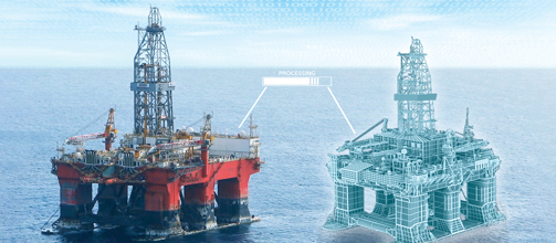
DIGITAL TWIN
Asset integrity management programs are dependent on a combination of labor-intensive inspection, analysis and measured data. A digital twin is a digital replica of the physical asset, in this case the drilling riser system and MODU. This digital representation of the system provides the basis of how the asset responds under various operating conditions. The system digital twin integrates a computer model of the physical system together with response data of the system, and data analytics, to create a living digital simulation of the system as the asset undergoes various operations.
A digital twin model of the global drilling riser and MODU has been developed and can be used to view the fatigue loading of the actual drilling riser joints; as SVDLs collect data, the SVDL data is used to update the digital twin. The digital twin is meant to be an up-to-date and accurate copy of the drilling riser and MODU’s properties and response status.
The digital twin also can be used for monitoring and diagnostics to optimize asset performance and utilization. The sensor data (SVDL, rig response) can be combined with historical data, human expertise, and fleet and simulation learning, to optimize performance and improve productivity.
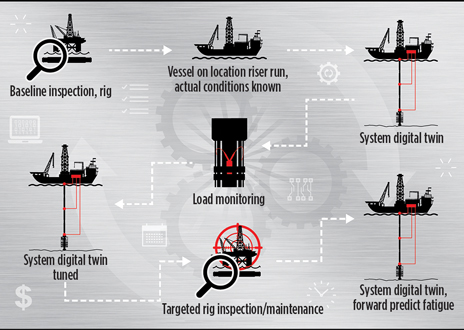
The fatigue damage along the drilling riser is tracked in a digital twin from rig data, such as vessel heading, current profile, sea states, top tension and mud weights. The stresses and hence fatigue loading experienced throughout the string are simulated, using the data collected from the vessel, Fig. 3.
Using fatigue analysis methods and fracture mechanics, together with rain-flow cycle counting, the cumulative fatigue damage on each riser joint is estimated. The specific joints that accrue high levels of fatigue damage are then scheduled for further inspection, based on usage metrics rather than a calendar basis.
PROGRAM BENEFITS
The end users of the program are the drilling contractor and operator. The drilling contractor stands to experience lower inspection costs, as major inspections are performed per operating conditions versus set time intervals. The drilling contractor’s riser asset management is enhanced, with fewer spares required, due to fewer instances of risers being out of service. Lower logistical costs are experienced, with less call for risers being transported back and forth by boat (this saving is even more critical in remote campaigns). Reduced inventory swapping may reduce between-well time and rig non-productive time, saving the operator significant expenditure.
CONCLUSION
The approach to moving to a life cycle condition-based maintenance, monitoring and inspection system, which can be deployed on the MODU, removes uncertainties surrounding damage of riser joints and will allow the owner to determine whether a riser should be redeployed or replaced. This is the only process that is ABS-approved for condition-based monitoring of drilling riser systems. The system is compatible with all present owners’ maintenance programs and ensures that maintenance requirements are supported with robust engineering. WO
- Advancing offshore decarbonization through electrification of FPSOs (March 2024)
- Digital transformation/Late-life optimization: Harnessing data-driven strategies for late-life optimization (March 2024)
- The reserves replacement dilemma: Can intelligent digital technologies fill the supply gap? (March 2024)
- Subsea technology- Corrosion monitoring: From failure to success (February 2024)
- Digital tool kit enhances real-time decision-making to improve drilling efficiency and performance (February 2024)
- Digital transformation: Digital twins help to make the invisible, visible in Indonesia’s energy industry (January 2024)
- Applying ultra-deep LWD resistivity technology successfully in a SAGD operation (May 2019)
- Adoption of wireless intelligent completions advances (May 2019)
- Majors double down as takeaway crunch eases (April 2019)
- What’s new in well logging and formation evaluation (April 2019)
- Qualification of a 20,000-psi subsea BOP: A collaborative approach (February 2019)
- ConocoPhillips’ Greg Leveille sees rapid trajectory of technical advancement continuing (February 2019)

