A new generation of HPHT sand screens developed
Sand control is an essential component of many wells. Each year, operators are forced to expend significant amounts of capital to prevent and repair downhole sand control failures. Additional revenue is lost in reduced production time and less-than-optimal daily rates.
Several downhole sand control technologies have been developed over the years, with stand-alone and gravel pack screens being the most common. Unfortunately, these systems have been afflicted by erosion and/or corrosion issues. Hostile fluid environments across the pH and salt spectra can corrode, and limit, life expectancy of screen parts, while the constant barrage of hard/abrasive sand particles erodes the screen and widens its slots. This leads to partial or total loss of sand control throughout the hydrocarbon production cycle. And HPHT environments, typically defined as >150°C and >10,000 psi/bar, exacerbate these problems.
CERAMIC SCREEN DEVELOPMENT
The lack of universal standards for sand screens made it difficult for science and technology companies to define a suite of globally accepted testing protocols to aid technology development. In spite of this situation, a Danish oil and gas company began a collaboration with ESK Ceramics (now 3M Advanced Materials Division) in 2008, to develop a new sand screen material, using technology derived from 3M’s existing technical ceramics platform including:
- Military armor—material is lighter/harder than metals and alloys.
- Mining sector—ceramics’ erosion-resistant characteristics reduce NPT.
- Oil and gas—topside applications.
After two years of determining measurement parameters and testing various designs, the first ceramic sand screens, using silicon carbide, were deployed successfully. To date, ceramic sand screens have been installed in 30-plus wells, in various worldwide locations, including producers where conventional sand screens have failed. The screens also have been used successfully in gas wells with high-rate erosion velocities (>100 ft/sec) in the perforations, and on production sites where a costly deployment of gravel pack was avoided.
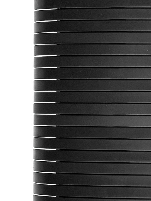
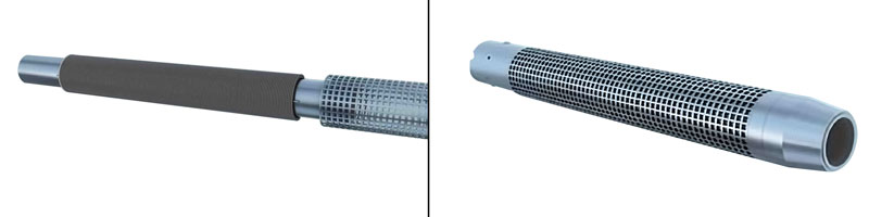
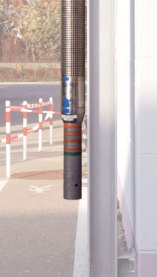
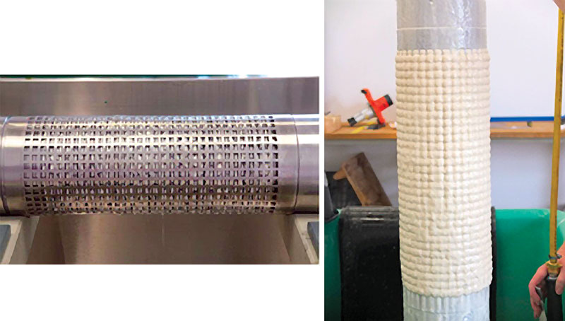
The ceramic sand screens employ a flexible stack of ceramic rings, Fig. 1. A customized V-shaped gap between the rings is based on the particle size distribution of the sand at the drilling site. The ring stack is covered with a protective shroud (Fig. 2a), while end caps capture and protect the ceramic stack and anchor the assembly to the base pipe, Fig. 2b. This design encourages a natural sand pack formation around the ceramic sand screen while reducing the risk of compromised productivity.
Methodology of qualification criteria. The biggest challenge to effectively defining sand screen qualification and validation criteria for HPHT environments was defining relevant benchmarks. Engineers also had to design a method to reliably transition from laboratory testing and surface technical qualification to specifications suitable to meeting downhole HPHT production requirements. Although some testing qualifications could be derived from ISO 17824 (19s), a more complete qualification methodology had to be developed in partnership with operating companies.
Each operator selected different critical parameters to be tested and qualified, to endorse a technology for field conditions. After data analysis, parameters for erosion, robustness, corrosion, burst/collapse, and bending qualifications were agreed upon, which ensured risk-mitigated deployment and placement in hole. This approach required understanding from both the operators and the screen manufacturer to ensure alignment of objectives, transparency of testing protocol, and a shared understanding of downhole conditions and the required specifications of the product.
Qualification protocol. The following testing was defined as necessary by operators and the manufacturer, to qualify a ceramic screen for general HPHT applications.
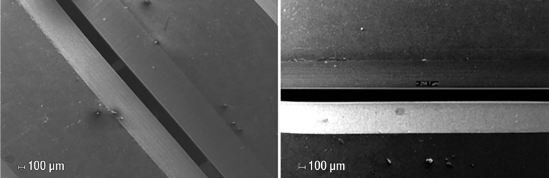
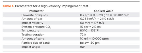
Erosion. For sand screens, high-velocity impingement testing entails projecting sand particles at a representative coupon. Testing parameters are listed in Table 1, and were mutually defined by the project team, based on operator well requirements. Tests were conducted on ceramic coupons with a 250-µm slot opening. The post-test ceramic coupon was magnified with a SEM, Fig. 3. No deformation, fracturing of the coupon, or a widening of the slot opening was detectable.
Robustness. Because HPHT generally exhibits deeper and more complex well architectures, and wellheads can be on a platform and subsea, impact tests were performed to ensure that the integrity and functionality of the screens would be preserved under normal deployment conditions. Complete HPHT sand screen assemblies were driven into a hard surface to mimic exaggerated sand screen deployment conditions, Fig. 4. After 100 impacts, no critical damage occurred.
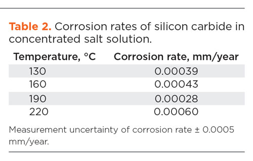
Corrosion. High H2S and CO2 concentrations and salt-rich environments are common in HPHT wells. The base silicon carbide material was tested in a 96% H2SO4 solution at two temperatures between 150°C and 220°C. Even at the higher temperature, only minimal loss was measured within the limit of detection, Fig. 5. Corrosion also was measured after 28 days in a highly concentrated salt solution. Again, even at high temperatures, loss was negligible, Table 2.
Collapse and burst. Aligned to ISO 17824 (API 19s), which covers sand screen collapse and burst testing, ceramic sand screens were tested, both at the screen manufacturer’s qualification testing facility and at third-party laboratories. The manufacturer developed a plugging pill aligned with the ISO standard, which could withstand a burst pressure of 1,500 psi and differential collapse pressure above 7,500 psi, which was the test rig’s limitation, Fig. 6. These results fulfill the known requirements
for HPHT.
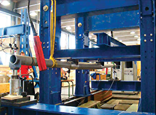
Bending. The integrity of ceramic rings and deformation of metal parts were investigated after bending. Figure 7 shows the testing set-up. The aim was for the change in mean slot opening to be less than two gauge (50µm), post-relaxation of the bending forces.
TEST PROCEDURE/RESULTS
After establishing an operator/manufacturer-derived set of HPHT qualification and validation criteria, the following test procedures were implemented.
- Mount the screen with in-situ measurement system on the test rig.
- Measure the distance between inner supports of the test rig.
- Adjust the displacement transducers and connect to a data recording system.
- Bend the screen by pressurizing the hydraulic jacks until the
displacement measured at the ceramic rings corresponds to the dogleg. - Measure the slot opening, before and after applying loads to measure the change in the slot opening.
Test results on a 4½-in. base pipe, ceramic screen assembly:
- The change of slot opening measured at a dogleg of 12.7°/100 ft was maximum 10 µm.
- The change of slot opening measured at a dogleg of 25.2°/100 ft was maximum 23 µm.
- After relaxing the loads, there was no change in slot opening from the defined design specifications.
- Theoretical finite element modeling for the same screen size was performed, and it produced similar results.
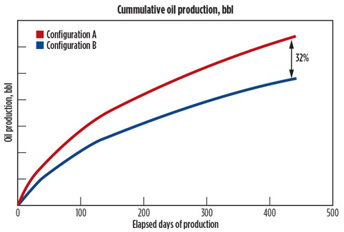
Case study. An operator required a method to limit topside investment and contain proppant downhole in a high-velocity environment where production rates ranged between 25 to 35 MMscfgd. Two wells were equipped with a ceramic sand screen system. A wireline was deployed and the screens were hung from a packer then set across the upper perforation zone. The wells have been on-line since the end of 2014 and have continued producing with no proppant flowback seen at the surface. Future wells will be completed in the same manner.
SUMMARY
The qualification process to specifications in a HPHT sand screen design was successful. The defined changes ensured that each testing scope was relevant for general HPHT environments.
Defining the qualification steps was an iterative learning process, with constant input from the operators to fully understand the requirements pertinent to HPHT sand control. This discussion transferred operator competency and knowledge to the manufacturer.
The ability to use particle testing competence and ISO norm specification for ceramic sand screens enabled 3M to define testing protocols, to ensure correct qualification within the HPHT sand control market. The resulting specifications in design are for an envelope of operation of 200°C and 20,000 psi bottomhole static pressure.
This new technology adoption, through a defined project management process and partnership with the market, will help transform sand control in HPHT projects, which generally have more adverse operating conditions than conventional projects. ![]()
- What's new in production (February 2024)
- U.S. operators reduce activity as crude prices plunge (February 2024)
- U.S. producing gas wells increase despite low prices (February 2024)
- U.S. oil and natural gas production hits record highs (February 2024)
- Dallas Fed: E&P activity essentially unchanged; optimism wanes as uncertainty jumps (January 2024)
- Enhancing preparedness: The critical role of well control system surveys (December 2023)
- Applying ultra-deep LWD resistivity technology successfully in a SAGD operation (May 2019)
- Adoption of wireless intelligent completions advances (May 2019)
- Majors double down as takeaway crunch eases (April 2019)
- What’s new in well logging and formation evaluation (April 2019)
- Qualification of a 20,000-psi subsea BOP: A collaborative approach (February 2019)
- ConocoPhillips’ Greg Leveille sees rapid trajectory of technical advancement continuing (February 2019)

