Torque and drag system enables automated casing monitoring
Casing design has evolved significantly over the years, with recent developments attempting to address the needs of the extended-reach drilling market segment. In particular, the main focus of casing design improvements has been the pursuit of ideal methods to get the casing to bottom more effectively and safely. One underlying issue that impacts whether a casing run is successful, or not, is the influence of torque and drag on the casing. While there have been some developments in casing features that are designed to reduce torque and drag, a need was determined for a system that can truly track torque and drag trends, in real time, during a casing run.
To drive the implementation and impact of new technology and address the fluctuating economic and operational environment, National Oilwell Varco developed an automated system, based on a complex software algorithm, that captures torque and drag data and monitors casing. The real-time system provides information on downhole friction and hole issues during deviated drilling operations, with real-time guided- and automatic-capture modes eliminating the need for manual data entry and reducing the risk of human error. Remote access enables shared capabilities at the rig site and collaboration from anywhere in the world.
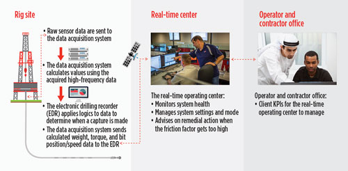
Though it is crucial that operators mitigate drag issues while running a variety of wellsite operations, maintaining the casing’s integrity is usually a priority. The automated torque and drag system enables simple monitoring and troubleshooting of the casing run while operations are in progress. The system is designed to alert the driller to impending issues in real time, with an operating center utilizing live torque and drag data to conduct analyses and make recommendations, Fig. 1.
The system works in conjunction with rig site instrumentation, using existing high-frequency surface sensor data to sample hookload and torque, and intelligently determine torque and drag data. These data are sent to the driller and displayed on a rig floor-mounted screen, where they can be managed remotely by the real-time operating center. This ensures that the driller is provided with feedback and recommendations on remedial actions, based on observed wellbore conditions.
A major challenge for remote, real-time drilling optimization, and a real-time operating center, is to determine how to have a significant, positive impact on operations. In addition, it is critical that the time between identifying a potential incident, and acting to resolve it, be minimized. Typically, real-time operating centers have relied upon real-time analysis and advanced optimization software to view drilling data and manage the planned-versus-actual results. Though there is merit to using these systems, and the information they provide is useful, the data loses applicability by being unavailable to the drilling crew and the driller in real time.
Tracking actual torque and drag values has, traditionally, been done manually during drilling, tripping and casing runs, and not always at every stand. This method, generally, yields lower-density data, and is subject to human interpretation. One driller, for example, might record hookload at a different time when slacking off than another. In this scenario, implementation of an automated system would remove subjectivity from the equation. In addition, the system removes a redundant task from the driller’s routine and allows for instant back-office visibility.
In the past, torque and drag data that were recorded manually were sent to the office after a run was partially completed, or when standard morning reports were submitted. Eliminating the time lag between recording the data and delivering them has become a distinct desire of companies needing to increase efficiency, in ways that haven’t been considered previously.
In worst-case scenarios, failing to quickly address torque and drag concerns can lead to significant losses of drilling time, and severe damage to casing and downhole equipment. Post-run analysis of torque and drag data after catastrophic casing run-in issues, in fact, usually shows that some warning signs presented themselves in the time leading up to the event. By having an automated “push-through” of data to the back office, rather than waiting for periodic reports, those catastrophic events are visible to the engineering team and/or the real-time operating center at the instant they occur. Being able to see the data so quickly allows for a swift analysis of the problem and a recommendation of remedial action to the drilling crew, allowing them to reach total depth (TD) without damaging the equipment and/or the casing.
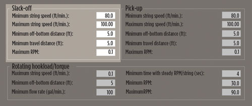
The automated torque and drag system follows a logical test to determine key torque and drag data points, such as pick-up and slack-off hookload, free-hanging weight, off-bottom torque, break-over torque and break-over hookload values, Fig. 2. In the context of running casing, each connection is detected automatically by the system, and slack-off hookload is recorded and superimposed over the friction-factor roadmap. If string speed remains within a defined boundary, the casing string is off bottom, and the blocks travel a certain distance, hookload is captured and recorded as a slack-off weight. The minimum hookload also can be plotted to aid in the determination of events, such as differential sticking.
While on the rig floor, it is beneficial if the driller can quickly understand what hookload is acceptable at a given depth while running casing. The automated torque and drag system features a smart hookload alarm system that scales with depth, rather than with an absolute set minimum. The user can select a defined friction that has been uploaded to the system and a threshold above which is considered a safety tolerance. If hookload drops below this threshold when running in the hole with casing, an alarm is sounded. This feature can alert the driller at the instant he approaches a limit, such as that of helical buckling, and allows him to pick up and take remedial action to prevent the buckling from occurring.
Friction is the most critical issue that limits drilling beyond a certain depth in complex trajectories. As the modeling of drillstring mechanics has become more advanced, it has become clearer that friction has a noticeable impact on the buckling phenomenon. More specifically, one of the most significant factors impacting casing operations is helical buckling, an extreme form of buckling that occurs as axial compressive load increases beyond that of sinusoidal buckling and exceeds the helical buckling limit.
The major concern with helical buckling is that it causes more contact between the pipe and wellbore, thus causing the casing to coil within the wellbore and reach a level of axial friction that cannot be overcome with its own weight. Drillstring fatigue and interference with weight transfer to the bit are the most common results of helical buckling, and when the hookload crosses the helical threshold, the casing can “stack out,” or fail to progress further downhole. The automated torque and drag system addresses these concerns by allowing visualization of hookload trends, which indicates that the helical limit is being approached before it is actually reached.
PERMIAN BASIN
Automated casing monitoring using the torque and drag system has already seen application in several projects. Three Rivers Operating Company (3ROC), working in Culberson County, Texas, needed to acquire and evaluate accurate torque and drag data in real time, to automatically monitor casing and quickly identify operational dysfunctions. The automated torque and drag system was deployed during ongoing operations, allowing the operator to identify over-pulls, tight spots, and other drag issues in real time, enabling swift and efficient corrective action while ensuring that equipment integrity remained intact. The system also allowed 3ROC to automatically capture data, create a casing roadmap, and minimize early casing setting, due to stuck issues.
A casing model was designed, using finite element analysis software and the technical specifications provided by 3ROC. During drilling operations, torque and drag values validated the model and aided in correction of friction factors and weights, causing the model to run as close to real values as possible. After the friction factors were corrected and validated, they were used to model the casing run, which enabled drilling engineers to have a more accurate prediction of how drag would affect the run. In addition, the casing model provided the drilling engineers with more confidence on whether or not the casing would reach TD, and gave an early warning of drag concerns before they became a major issue.
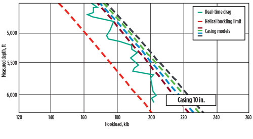
On 3ROC’s production casing run, which had an outer diameter of 4.5 in. the casing model was produced, using the corrected friction factors from the last trip out of hole by the drilling BHA, well before the casing run started. The casing model and data captures were compared in real time, using the automated torque and drag system to observe trends, allowing 3ROC to proactively engage in mitigating any drilling dysfunctions that could affect the casing. 3ROC was casing the hole up to 6,400 ft and filling up the liner every 10 stands.
At approximately 3,537 ft, 3ROC was notified of changes in tripping speed from 50 ft/min. to 30 ft/min. during the operation. At approximately 5,681 ft, the hole became tight, where the real-time data captures approached the helical buckling limit. Personnel in a real-time operating center notified 3ROC immediately, whereupon the rig began washing and reaming down to make the casing operation successful. 3ROC avoided the casing passing the tensile limit capacity of rig site/pipe equipment and reached TD without any damage to the equipment or casing, Fig. 3.
MONTNEY SHALE
A client operating in Canada’s Montney shale needed to acquire torque and drag data in real time, to ensure good hole cleaning, eliminate nonproductive time (NPT), and enable control and monitoring of wellbore friction. To achieve this, the automated torque and drag system was used in the client’s three-well batch-drilling campaign to develop a real-time production casing model and automatically follow the casing run.
The operation consisted of three intermediate sections, where the well would build from vertical, to land at 90° inclination and three lateral production sections of more than 6,562 ft. The client was able to use the automated system to effectively monitor torque and drag while drilling, ensuring good hole cleaning that enabled the driller to further increase ROP. Drilling and tripping data also were used in real time to automatically update friction factors for casing operations, allowing each casing run to reach TD.
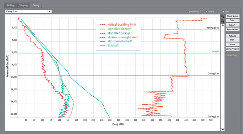
All three wells of the campaign were drilled without NPT caused by tight holes, poor hole cleaning, or stuck pipe while drilling, and all casing runs reached TD successfully. The automated system proved valuable in monitoring wellbore conditions, both at the rig site and remotely, equipping all members of the drilling team with an effective solution for addressing torque and drag concerns, Fig. 4. By automating casing monitoring and obtaining downhole data in real time for immediate analysis, the client was able to take action effectively, as drag drew into close proximity of the helical buckling limit. Though that limit was passed at certain points near the end of the run, the client took corrective action quickly enough to prevent the buckling from becoming critical and reached TD without issue.
Though the oil and gas industry is changing constantly, casing monitoring and protection will continue to be one of the most critical components of the drilling process. Moving forward, it will be important to develop improvements, not only to the casing itself, but to the technologies that complement casing operations. As pipe movement in deviated wellbores is guaranteed to produce torque and drag along the drillstring, operators must ensure that such torque and drag is utilized effectively, and does not exceed certain limits, to avoid costly equipment damage and operational delays.
Developing a casing model to assess torque and drag values in real time, and their relation to casing integrity, is the first critical component of innovation in this space. The second is implementing automatic casing wear monitoring, which alleviates the burden placed on the driller to manually capture, and record, torque and drag values. Together, they represent a casing advancement that reinvents and optimizes a very traditional process. ![]()
- Driving MPD adoption with performance-enhancing technologies (January 2024)
- Rig electrification drives down emissions, bolsters efficiency while improving onshore drilling economics (October 2023)
- Wellbore seal control and monitoring enhance deepwater MPD operations (October 2023)
- Advancing casing drilling to deepwater: Rethinking top hole well construction (August 2023)
- Mobile electric microgrids address power demands of high-intensity fracing (July 2023)
- Utilizing electronic data captured at the bit improves PDC design and drilling performance (July 2023)

