Classification rules aim to advance deepwater MPD applications
Over the past decade, managed pressure drilling (MPD) techniques have gained wider acceptance for deepwater applications.1,2,3 Their success is attributed largely to the ability of rotating control devices (RCDs) and other MPD pressure-control technologies to create a closed-loop drilling environment with instantaneous adjustment of backpressure. While MPD methods are relatively routine for drilling land and shallow-water wells that employ a surface BOP, the extension of MPD to deepwater applications has left many operators with questions about reliability, barriers, riser gas management (RGM) and general riser interface issues.
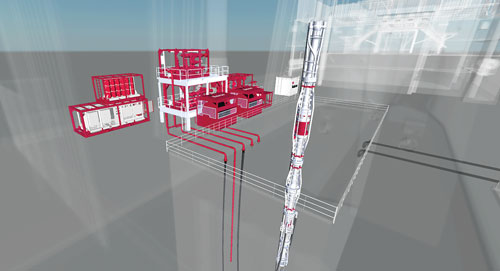
Generally, the industry considers any proposed MPD integration on a deepwater rig to simply be a modified extension of its onshore counterpart, Fig. 1. However, the equipment, and the uniquely complex rig-up on semisubmersibles and drillships that it requires, have not been covered explicitly in any offshore-specific rules, regulations or class-society requirements. A new drilling rig classification protocol for deepwater pressure control systems was required, to provide systematic guidelines for the installation, commissioning, approval and execution of multiple, closed-loop drilling techniques on classed mobile offshore drilling units (MODUs).
CLASSIFICATION RATIONALE
The forthcoming 2018 American Bureau of Shipping (ABS) Guide for the Classification of Drilling Systems (CDS guide) includes the latest safety standards applicable to MPD systems used in global shallow-water and floating-rig applications. The guide’s framework for standardization of the equipment, distinctive rig-up challenges, and operation of MPD packages for floating drilling rigs, arose from extensive offshore integration experience and learnings from working with MPD providers and regulatory agencies.4,5 The value of class notation and certification for drilling systems is important, because it provides offshore operators and regulators an increased level of confidence in the safety and integrity of pressure control systems commissioned for drilling challenging wells.
The MPD appendix to the CDS guide addresses the temporary and permanent conversion of rigs from conventional drilling equipment to pressure control systems suitable for MPD. The process begins with front-end engineering design, followed by a review of the operator’s documentation of hazards and safety concerns specific to the MPD equipment to be deployed. Multiple levels of safety assessment are carried out including: 1) hazard identification (HAZID); 2) hazard and operability analysis (HAZOP); 3) failure mode, effects and criticality analysis (FMECA); and 4) safety integrity level (SIL) assessment.
Once the ABS and the drilling contractor have identified existing marine and offshore requirements and standards, a gap analysis is conducted on the integrated rig and MPD systems to identify areas of the proposed design for which no relevant marine standards exist. From there, the MPD provider, drilling contractor and ABS jointly apply first principles of engineering and risk assessment methodologies to identify and manage hazards. However, ABS standardization addresses only mechanical integrity, reliability and safety aspects, and does not provide guidance for design optimization with respect to drilling efficiencies or economic returns.
The CDS guide appendix addresses a number of significant challenges. For instance, a below-tension-ring RCD is exposed to hydrodynamic loading, as well as hydrostatic pressure, induced tension, vortex-induced-vibration, heave, and torsional weather-vaning loads not present in onshore applications. In addition, the integration of an MPD package on a MODU designed with a conventional open-to-atmosphere circulating system requires fail-safe systems with full redundancy. A number of additional areas of study are being considered to improve offshore safety:
- Interfaces for flow and control lines
- Changes to the network of piping, umbilicals and hoses in the moon-pool area
- A nodal safety assessment of the system
- The adoption of a unified well-control philosophy by the operator, contractor and service company.
While global offshore safety falls under numerous layers of regulatory oversight, from the International Maritime Organization to more centralized flag-state and local jurisdictions, MPD-specific issues typically are addressed sparingly with often overlapping requirements. Further, limited documentation pertaining directly to offshore MPD can be found among the myriad of technical standards adopted by the American Petroleum Institute (API), International Organization for Standardization, American Society of Mechanical Engineers, European Norm, International Association of Drilling Contractors (IADC) and other industry groups.
The absence of applicable, published recommended practices or standards created an opportunity for the development of an MPD appendix to the 2017 ABS CDS guide. The key objectives of the new appendix are to enhance safety, integrity and reliability, and to instill increased confidence in the use of MPD technologies in shallow-water and deepwater wells worldwide.
NEW MPD CLASSIFICATIONS
The appendix spells out the core steps and considerations required to achieve classification of an MPD system for a classed MODU. The standards are the result of an interdisciplinary collaboration centered on the major equipment and process categories that differentiate the integration of MPD in an offshore, and particularly a deepwater environment. To obtain regulatory buy-in and avoid deployment delays, it is critical that the classification society and the respective flag-state regulatory agencies be engaged at the onset of a proposed MPD integration project. For example, in U.S. territorial waters, relevant parties would include the Bureau of Safety and Environmental Enforcement (BSEE) and U.S. Coast Guard authority.
Technology evaluation. For an MPD system to receive ABS certification for offshore installation, it must, at a minimum, satisfy the new criteria outlined in the appendix to the CDS guide. First, ABS and the equipment supplier must jointly identify the risks and concur on the appropriate mitigation measures. Risk assessment techniques must be used to address site-specific and other concerns not included in existing ABS rules or other international standards, rig contractor standards, or operator standards. Once the risks have been identified, the equipment provider must apply appropriate mitigation measures to reduce overall risk to an acceptable level. This means that the primary barrier envelope for the well is at least as effective as, or better than, the envelope for conventional offshore drilling practices.
Process safety. Conventional well-design philosophies are based on ensuring functionally independent primary and secondary barriers, as stipulated in the API Recommended Practice (RP) 59 for well-control operations. API RP 59 defines primary well control as the maintenance of hydrostatic pressure in the wellbore, equal to or greater than the formation pressure to prevent formation influx. Since MPD creates a closed well-circulation system that contributes directly and actively to the prevention of an influx, MPD systems logically should be considered a part of the primary well barrier.6 MPD systems are designed in accordance with API 6A, 16A, 16C, 16D, 7K, 17K and 92 series and as such are equal in integrity to the well-control systems already installed on rigs. Because of this capability, downhole events can be circulated safely through the MPD pressure control system to avoid nonproductive time.
As part of a dynamic pressure control process, MPD systems can control dynamic wellbore pressures with considerably greater levels of precision, compared to conventional drilling techniques. This is achieved by rapid, precise control of bottomhole pressure, and measurement of mud flow, in and out of the wellbore. The precision of MPD measurement and control has been shown to materially improve drilling efficiencies by segregating well monitoring and pressure control from the mechanical drilling operation. Full-time surveillance and pressure control services increase real-time awareness of subsurface conditions, and allow the application of the best combination of operating and safety philosophies.
The safety philosophy underlying MPD operations on MODUs is to reduce the risk of uncontrolled well flows, with two differing approaches being adopted: 1) the first focuses on detection, control and riser gas mitigation (RGM); 2) the second uses riser gas handling (RGH). Both approaches rely on the BOP as the ultimate means for securing the well. While these methods appear similar at first glance, the two approaches are fundamentally different with respect to the basic strategy for handling gas in the riser. The RGM approach relies on manual and automated pressure control, and early-kick-detection techniques, to limit the amount of gas entering the riser.
If riser de-gassing is required, the MPD system is used to continually boost the riser and keep the gas event strung out in the well, lowering the intensity of the peak pressure before the gas reaches the surface. In contrast, advocates for the RGH approach require that the riser, flow spool, flowlines, MPD choke manifold, and mud-gas separator are capable of safely handling a large influx volume. This approach is not automated and requires human intervention to activate. It also relies on the drilling contractor maintaining the integrity of a gas-handling system that is essentially on cold stand-by. Using this approach, a riser unloading event may terminate before the RGH system can be activated.
Well control. The primary well barrier for a deepwater MPD operation is provided by the fluid column and choke-applied surface backpressure. Thus, the riser, RCD, flow spool, hoses, MPD choke manifold and other elements of the primary well barrier should be designed as pressure-containing and pressure-controlling components. This is according to terminology contained in the API standard for maximum anticipated surface pressure, tension, dynamic loading, erosion, peak-event intensity and mud-gas-separator throughput.
For onshore wells, the limit for surface pressure is determined by a specific company’s operating philosophy. However, in deepwater pressure control systems, the design capacity should be calculated, based on conservative estimates of maximum allowable kick volume and kick intensity. Substantial increases, either of volume or intensity, or both, are then comfortably within the system’s design envelope. Therefore, any boundary condition imposed by the operator, or drilling contractor, via the MPD matrix, is likely to be significantly less than 100% of the true system capacity. This large safety factor should provide a sufficient margin for the system to safely contain any unforeseen incidents.
The operator-imposed surface pressure relief valve (PRV) settings also provide an added layer of safety assurance to protect personnel, assets and the well from overpressure. This presumes that a well’s pressure profile is actively managed by detecting influx volumes that might exceed normal associated gas fractions. The combination of conservative limits on influx volume, combined with pressure relief, ensures that the riser is protected against an inflow capable of exceeding the riser’s nominal pressure rating.
Pressure protection. One factor that must be addressed, at the onset of MPD integration into a floater, is assurance that the marine riser will not be overpressured under normal or emergency operating conditions. The control systems used to actively manage the well’s pressure profile must, therefore, rely on automated software algorithms and hardware. Any failures involving these components could result in a loss of hydrostatic control, leading to an influx that exceeds the normal operating thresholds set for nuisance gas and controllable influxes. The automated system safety and equipment architecture must use design principles embodied in surface production facilities. The resulting MPD system will include functionally and physically independent basic process control systems, safety-instrumented systems and safeguarding systems.
The advantage gained from adopting this philosophy is the presence of two independent barriers, and subsequent verification that properly engineered safeguards are in place to reduce the risk of over-pressuring the riser. As always, the BOP provides the driller with a means to secure the well in the event of a loss-of-control event.
Others advocate using a specialized PRV to protect the riser from overpressure. While this may be suitable for an RGH system that utilizes sufficiently sized flowlines and a mud-gas separator, for an MPD pressure-control system, the design premise and functional design specification of the entire system are built around an understanding that the peak event is controlled to within design limits. When an event is greater than the system can handle, the rig must revert to conventional well control. To address this situation, each operator must develop and communicate an MPD well control matrix that takes the well’s actual limiting conditions into consideration, and the functional design specification of the MPD pressure control.
Tiered hazard analysis. The process of integrating an MPD system onto a deepwater MODU must adhere to all regulatory requirements and assure that all HSE safeguards have been assessed and, when required, implemented. To this end, a comprehensive hazard analysis and risk assessment are undertaken and tested against accepted concepts, such as “best available safest technology” and “as low as reasonably practicable.” The ABS guidelines include tiered hazard analyses, starting with HAZID followed by FMECA and, finally, HAZOP, once preliminary piping and instrumentation diagrams are available. Engineering, operations and field personnel typically participate in these risk-assessment steps.
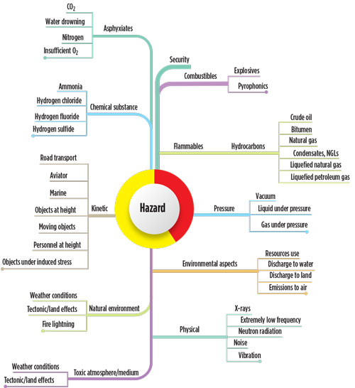
As MPD operations introduce new hazards on a floating MODU, it is important to identify these risks and determine the measures needed for prevention, detection, control and recovery. Accordingly, a HAZID should be carried out early in the feasibility design phase of a project, and structured around hazard checklists that help identify the effects of failures or process upsets, Fig. 2.
As equipment component failures can cause a loss of critical operability or safety function, a functional or component FMECA is highly recommended. Experience has shown measurable differences between the fault tolerance of similar equipment provided by different vendors. FMECA, therefore, is an essential step in demonstrating the equipment is reliable and fault-tolerant. FMECA should be carried out after detailed designs are completed, and ideally before manufacturing commences.
Safeguards to control or mitigate process upsets should be identified and assessed, using HAZOP, once all preliminary piping and instrumentation diagrams are available. HAZOP serves to ensure that credible causes of deviations are identified for each primary flow path, or node, and shows how each deviation will be brought under control using hardware or procedural measures.
Depending on the experience and knowledge levels of the teams carrying out critical, especially non-routine, activities, a procedural HAZOP may be undertaken. To avoid having to reissue the procedures, this process should take place before the drill-well-on-paper exercise has been completed.
A safety and operating envelope provides an opportune way of summarizing the key requirements determined during hazard analysis. Early on, the boundary conditions under which the MPD system would be deployed played a key role in educating ABS about the unique equipment and systems. This boundary, likewise, was fundamental in the development of a matrix for engineering design reviews, installation, testing, class survey inspections, and, ultimately, final acceptance.
Typically, the MPD service provider, operator subject-matter experts or a third-party engineering company, will develop an MPD well control matrix that outlines the boundary conditions under which the MPD system would be deployed. Early matrices played a key role in educating ABS about the unique equipment and systems.
The most important matrix is the nodal operations matrix, comprising the components used in each node with their respective serial numbers, pressure ratings, weaknesses, pressure protections, set points, maximum anticipated operating pressures and hydro-test values.
INTEGRATING RGH-MPD
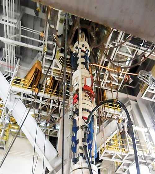
A real-world example of employing hazard analysis is illustrated in the retrofitting of an MPD package into a new RGH device on a recently launched drillship, Fig. 3. The rig came equipped with a gas handler integrated into the riser, which provided part of the components required for MPD pressure control. However, the fundamental design of the riser gas handler added technical and operational challenges. An RGH device is designed to fail closed at the outlet valves to keep gas in the riser until it can be vented overboard safely. When operating in MPD mode, it is preferable that these valves should fail as-is, because the trapped pressure could exceed the rated limits of both the RCD and riser. Another issue is that in MPD mode, the rig is drilling and pumps are running; therefore having fail-closed valves in the system could result in rapid over-pressuring of the riser, if they close unintentionally.
A full FMECA was undertaken to understand how the integrated system would fail, and how its failure modes and criticality would affect the safety of the system as a whole. Because it was impossible to change the fail position of the valves on the RGH package, the FMECA instead focused on understanding the severity of the failure and the means available to initiate operator intervention. A survey plan was then developed that included timing pump shutdown, valve closing, system identification, and operator response.
After the risk assessment was completed, and the testing witnessed and recorded, the data were submitted to ABS for review and approval. For future MPD upgrades, it is necessary to engage the RGH vendor and to develop a setup, wherein the valve fails as-is. This may be as simple as changing actuators when the equipment is used in conjunction with MPD. When MPD is not in use, and the riser gas handler is being used as originally designed, the original actuators can be reinstalled, tested and used. ![]()
REFERENCES
- Nas, S., J. S. Toralde, and C. Wuest, “Offshore managed pressure drilling experiences in Asia Pacific,” SPE/IADC paper 119875, presented at the SPE/IADC Drilling Conference and Exhibition, Amsterdam, The Netherlands, March 17–19, 2009.
- Barbee, B., C.H. Wuest, S. Bremner, and J.S.S Shaun, “In-situ retrofit sets milestone in deepwater MPD evolution,” published in World Oil, March 2016, pp 41–44.
- Hannegan, D. and K. Fisher, “Managed pressure drilling in marine environments” IPTC paper 10173, presented at the International Petroleum Technology Conference, Doha, Qatar, Nov. 21–23, 2005.
- Bruton, J. W., J. Lin, and H. N. Patel, “Practical MPD deployment considerations for floating drilling,” OTC paper 26227, presented at the Offshore Technology Conference, Brazil, Rio de Janeiro, Brazil, Oct. 27–29, 2015.
- Bruton, J. W., H. Patel, E. Dietrich and R. Prince-Wright, “Lessons learned and safety considerations for installation and operation of a managed pressure drilling system on classed floating drilling rigs” OTC paper 25946, presented at the Offshore Technology Conference, Houston, Texas, May 4–7, 2015.
- Jablonowski, C.J. and A.L. Podio, “The impact of rotating control devices on the incidence of blowouts: A case study for onshore Texas, USA,” SPE paper 133019, presented at the SPE Trinidad and Tobago Energy Resources Conference, Port of Spain, Trinidad, June 27–30, 2010.
- Advancing offshore decarbonization through electrification of FPSOs (March 2024)
- Subsea technology- Corrosion monitoring: From failure to success (February 2024)
- Driving MPD adoption with performance-enhancing technologies (January 2024)
- Digital transformation: A breakthrough year for digitalization in the offshore sector (January 2024)
- Offshore technology: Platform design: Is the next generation of offshore platforms changing offshore energy? (December 2023)
- 2024: A policy crossroads for American offshore energy (December 2023)
- Applying ultra-deep LWD resistivity technology successfully in a SAGD operation (May 2019)
- Adoption of wireless intelligent completions advances (May 2019)
- Majors double down as takeaway crunch eases (April 2019)
- What’s new in well logging and formation evaluation (April 2019)
- Qualification of a 20,000-psi subsea BOP: A collaborative approach (February 2019)
- ConocoPhillips’ Greg Leveille sees rapid trajectory of technical advancement continuing (February 2019)

