Structural vibrations of subsea piping systems stem from either external currents passing the structure (vortex-induced vibration, or VIV), or from transient flows of mixtures inside the pipes (flow-induced vibration, or FIV). These vibrations compromise the structural integrity of subsea systems and, in extreme circumstances, can reduce their fatigue lives from years to weeks.
The transient multi-phase flow inside subsea piping is complex, and gaining insight through physical measurements is expensive and challenging. As a result, the industry has relied heavily on simple analysis methods to predict the effects of FIV. These approaches tend to be overly conservative, making the decision process, concerning structural integrity of subsea piping systems, difficult. This has had a significant economic impact on the oil and gas industry, as failure is not an option, and expensive over-design is common practice for reducing risk. In extreme cases, failure to quantify FIV problems accurately can lead to reduced production rates, costing hundreds of millions of dollars.
CD-adapco is working closely with the industry to develop a set of best practices for modeling FIV. This work describes an example of how CFD is being used to complement other analysis methods, by providing higher-fidelity information that is otherwise unattainable, to reduce risk, reduce over-design and increase profit margins.
TACKLING THE PROBLEM
CD-adapco was formed, to establish or validate best practices for FIV. The ultimate goal is to contribute to the industrial capability of determining the likelihood of piping fatigue, due to excitation from multi-phase flow. Potential benefits could include screening improvement, simulation and prediction models through the use of CFD, and empirical methods.
This work is an example of slug flow in a jumper, modeled with two-way, fully-coupled fluid-structure-interaction (FSI).
The multi-phase flow encountered in jumpers covers the complete flow map, including slug, annular, dispersed, stratified and wavy flow. For simulation of FIV, it is critical that the movement of interfaces between different phases in the pipes is captured accurately, which means a multi-phase model is required. The volume of fluid (VOF) multi-phase model available in STAR-CCM+ was used to simulate the transient behavior of the mixture, and the development of slugs in the jumper. VOF uses the Eulerian framework. It is a practical approach for applications containing two or more immiscible fluid phases, where each phase constitutes a large structure in the system.
A key objective of this work was to address the need to understand the role that FSI plays in the fatigue life of subsea structures. The dynamic open architecture in STAR-CCM+ makes it well-suited to help provide answers, because it seamlessly enables FSI simulations, ranging from one-way coupling of either FIV or VIV, all the way up to two-way coupling, including the internal mixture and external flow of the pipes.
The focus of the simulation work is on FIV, using co-simulation (fully-coupled, two-way interaction), where STAR-CCM+ handles the multi-phase flow and Abaqus FEA is used for predicting the dynamic structural deformations of the jumper. The two domains are interconnected, using the SIMULIA co-simulation engine. Although this method is computationally intensive, it demonstrates a more general approach to the end user, because it can be deployed for predicting the behavior of complex systems, including non-linear structures and highly complicated geometries.
Alternatively, because the generic jumper geometry for this work is geometrically and structurally uncomplicated (e.g. there is no contact with the sea floor), this particular simulation also could be performed with a simpler approach by modeling the jumper with beam elements, using one-way coupling or completely performing the FSI problem in STAR-CCM+, using its structural stress analysis model.
In addition to direct co-simulation coupling with Abaqus, STAR-CCM+ also offers the ability to customize FSI simulations by leveraging the power of JAVA, which allows them to easily integrate their own legacy codes or FEA software for FSI simulations.
COMPUTATIONAL JUMPER GEOMETRY
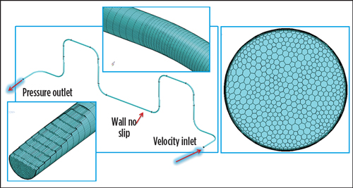
The generic jumper geometry in this study is made of steel, with a circular cross-section and a traditional M-shape. The jumper is clamped on both ends, and the multi-phase flow passing through the pipes consists of a 50-50 volume mixture of air and water. Fluid domain is extended, compared to the deformable structure, to avoid influence of boundary conditions on the flow inside.
For the VOF mesh, the generalized cylinder mesher available in STAR-CCM+ was used in conjunction with the polyhedral volume mesher. This approach works well for this particular application, because the geometry consists of cylindrical sections, and the direction of the flow is parallel to the vessel wall. Using extruded prismatic cells reduces the overall cell count, ensures orthogonal cells and improves the rate of convergence. The final VOF mesh has up to 4 million polyhedral cells and is depicted in Fig. 1.
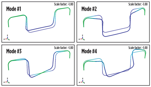
The Abaqus finite element model for the co-simulation consists of 21,000 four-node shell elements. First, a stand-alone, structural modal analysis was performed to characterize the dynamic behavior of the structure. The stiffness in each coordinate direction was computed by applying a load to the pipe to get the resulting force-displacement relationship, and an eigenvalue analysis was done to obtain the natural frequencies of the jumper. For this case, an equivalent mass, representing both the mass from the flow inside the pipes (assuming a uniform mixture of air and water), and the added mass resulting from the displacement of the water surrounding the pipe, was used. Figure 2 shows the first four natural modes of the jumper, and Table 1 lists the frequencies of each mode.
FIV ANALYSIS
STAR-CCM+ was first executed in a stand-alone mode, assuming a rigid, fixed structure. These rigid results were used to gain a better understanding of the internal forces, due to the mixture in the system, and served as the initial solution for the two-way, coupled co-simulation.

For co-simulation, on the VOF side, the second-order implicit segregated solver, using the k-omega SST turbulence model, was run unsteady with a time step providing a convective courant number value of up to 0.5 on most of the phase separation surface. This corresponds to 1/100th of the period of the fourth natural mode, and 1/63rd of the period of the seventh natural mode of the structure, and up to 1/150th of time for the mixture to travel along the pipe bend. Gravity was included in the simulation, and the inlet velocity was set to 3 m/sec, defined as 50-50 stratified flow, with water on the bottom and air on top.
The undeformed structure was used as the initial condition for the Abaqus runs. In addition to the added mass described above, the structural model also included a mass proportional damping to account for damping from the external water surrounding the pipes, as well as some additional damping in joints on jumper ends. The value of the damping coefficient, representing the mass proportional damping, was obtained by running a fully two-way coupled simulation on a flexible round pipe placed in water. For all simulations, attention was focused on the first seven natural modes of the structure, with their natural frequencies ranging from 0.59 to 2.82 Hz, Table 1.
The bends in the jumper are the primary locations, where significant loading occurs as a result of the large momentum from the change in direction of flow. Plotted test results identified the forces and their fast Fourier Transform (FFT) on each of the bends. It is clear that the multi-phase flow encountered by the bends is highly complex, with many identifiable peaks in frequency. This means that there are transient pressure loadings that have the potential to give rise to changing stresses and oscillatory vibrations, therefore affecting fatigue and lifespan of the jumper.
The primary, dominant frequencies observed in the FFT from the forces on the bends were low, with time scales of up to 10 sec, due to the separation of the phases in the mixture (development of slugs), as it flows through the jumper. Although these frequencies are much lower than the natural modes of the structure, they are a critical component for predicting the fatigue life of the jumper.
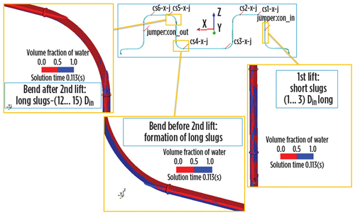
Figure 3 visually depicts the water volume fraction for each of the sections in the jumper and shows the evolution of the slugs, starting with the formation of short slugs, with an average length of up to 2 pipe diameters in the first lift. As the mixture moves through the jumper and arrives at the fourth bend, longer slugs are forming and, as they pass the second lift, they have reached a length of up to 12 pipe diameters long.

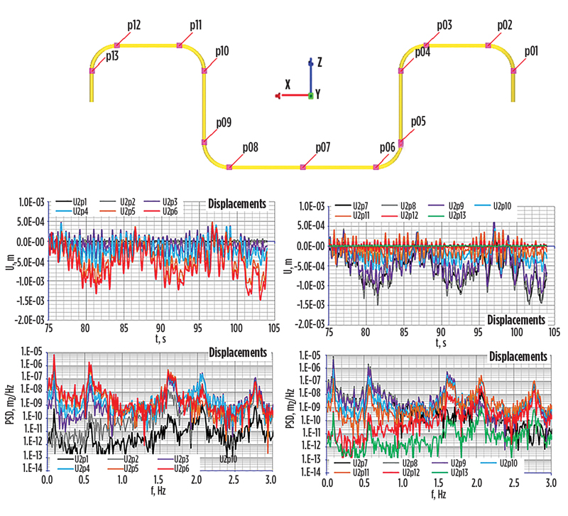
When taking a closer look at the dominant slug frequencies (Table 2), once again, it is observed that the slugs have relatively large time scales, with the first dominant frequency around 0.09 Hz. Because of this, each separate slug moving along the pipe produces impulse loading, resulting in structural vibrations, mainly with structural frequencies. This can be seen from the FFT of jumper displacements at controlled points, Fig. 4. In addition, one of the slug frequencies is observed to be close to the first fundamental mode of the system at 0.54 Hz, Table 2.
FATIGUE FAILURE PREDICTION
Von Mises stresses and displacements for the system were computed, and the largest tensile stresses were observed in the cantilevered section of the pipe that is clamped in the simulation and hooks into neighboring equipment in real-life scenarios. This location was identified as an ideal point for prediction of fatigue failure of the jumper, because a weld is usually located at this place, and it is subjected to tension at this point. The time-dependent behavior of the stress at this location, and its FFT, are shown in Fig. 5. A distinct peak with a dominant frequency occurs at 1.3 Hz and falls close to the frequency of the second natural mode.
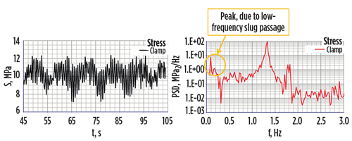
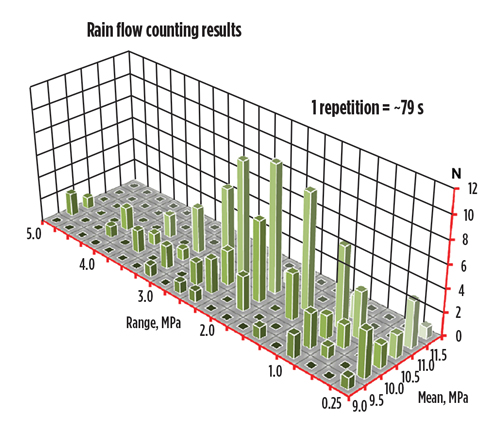
In addition, a low-frequency response of 0.09 Hz is once again present, due to the transient motion of slugs in the jumper. Using the results of the stresses at this critical location as an input, the rain flow counting technique was used to estimate the damage to the jumper from the presented portion of altering stress. The result, showing range in stress relative to the mean stress and number of cycles, is depicted in Fig. 6.
The Palmgren-Miner rule, using the S-N curve, predicted a short fatigue life of only about 5½ years. This is a good example that demonstrates the value of using high-fidelity simulation to assess fatigue life early in the design process. A potential, structural vibration problem is identified up front, and additional simulations can be performed at a low cost, to redesign the jumper and mitigate the problem.
Flow-induced vibration, and its effect on fatigue life of a generic jumper, were assessed using a two-way, coupled FSI simulation with STAR-CCM+ and Abaqus FEA. Simulations were performed with the multi-phase VOF model in STAR-CCM+, and were found to be very robust with minimal numerical problems. The dominant frequencies from the slug formation in this particular jumper geometry were much lower than the natural frequencies of the structure.
This suggests that a coupling between the fluid and structure could be treated via a one-way coupling. For a one-way coupling, however, the added fluid mass and added fluid damping, due to the internal VOF flow, would be particularly difficult to assess in any predictive manner. Therefore, these fully two-way, coupled simulations provide insight into the expected damping which, in turn, greatly influence the lifespan estimates.
Investment in more expensive simulation tools will be beneficial in failure analysis prediction and prevention for subsea systems. Anticipation of structural integrity early in the design space is expected to help quantify and reduce the amount of conservatism currently used by the oil and gas industry, keeping production flowrates as high as possible. ![]()
REFERENCES
- http://www.xodusgroup.com/press/press-releases.html
- “Guide for the fatigue assessment of offshore structures,” American Bureau of Shipping, Houston, Texas, 2010.
- Chica, L., “Fluid structure interaction analysis of two-phase flow in an M-shaped jumper,” University of Houston, College of Technology, Mechanical Engineering Technology. Star Global Conference, 2012.
- Pontaza, J.P., B. Abuali, G.W. Brown and F.J. Smith, “Flow-induced vibrations of subsea piping: A screening approach based on numerical simulation,” SPE paper 166661, Shell International Exploration and Production Inc., Shell UK Ltd., 2013.
- Pontaza, J.P. and R.G. Menon, “Flow-induced vibrations of subsea jumpers, due to internal multi-phase flow,” Shell Projects & Technology, OMAE2011-50062.
- Advancing offshore decarbonization through electrification of FPSOs (March 2024)
- Subsea technology- Corrosion monitoring: From failure to success (February 2024)
- Driving MPD adoption with performance-enhancing technologies (January 2024)
- Digital transformation: A breakthrough year for digitalization in the offshore sector (January 2024)
- Offshore technology: Platform design: Is the next generation of offshore platforms changing offshore energy? (December 2023)
- 2024: A policy crossroads for American offshore energy (December 2023)
- Applying ultra-deep LWD resistivity technology successfully in a SAGD operation (May 2019)
- Adoption of wireless intelligent completions advances (May 2019)
- Majors double down as takeaway crunch eases (April 2019)
- What’s new in well logging and formation evaluation (April 2019)
- Qualification of a 20,000-psi subsea BOP: A collaborative approach (February 2019)
- ConocoPhillips’ Greg Leveille sees rapid trajectory of technical advancement continuing (February 2019)

