Select optimum configuration for an offshore MEG recovery unit

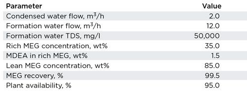
A newly discovered field, 50 km offshore, will be developed over the next five years, with production expected to come online in 2019. The production will be brought onshore, where it will be processed and delivered to customers. Given the location of the subsea wells and the production pressure/temperature profile, mono ethylene glycol (MEG) injection will be used to prevent the formation of hydrates. The Process Design Basis shows the information received from the Flow Assurance engineer, Table 1.
Rich MEG, delivered to the MEG recovery unit, typically comes from the plant slug catcher and inlet separator. This liquid feed typically contains a high level of dissolved hydrocarbons (0.5–2.0 vol%), including a high concentration of CO2. If left in solution, these hydrocarbons could accumulate in the process, leading to foaming, reduced boiling, or throughput issues with the vacuum compressor. To remove these dissolved hydrocarbons, a rich, MEG flash vessel will be included in the design.
MEG RECOVERY UNIT CONFIGURATION
The Rich MEG has a salt content of 2.4 wt%, while the Lean MEG specification is 85 wt% MEG on a salt-free basis. Assuming the Regenerator section of the MRU only removes water, the Lean MEG exiting the Regenerator will contain 5.82 wt% salts. At this level of salt content, the Lean MEG will contain free solids, which will precipitate inside the Regenerator. This precipitation will likely occur on the outside of the tubes in the kettle reboiler, which will lead to scaling, fouling, local hot spots, and reduced throughput.
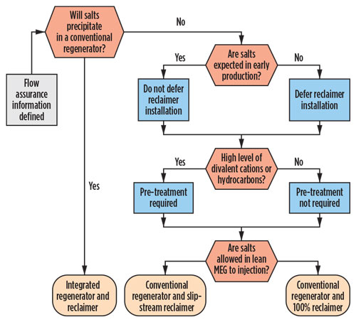
There are several different configurations and options that can be considered as part of the MEG Recovery Unit. Figure 1 provides a high-level decision tree that can be used to determine which configuration and options are appropriate for any application. There is some leeway in the application of this tool, which is based on experience gained during the last 15 years.
It already has been determined that a conventional Regenerator will result in precipitated salts, which leads us to an Integrated Regenerator and Reclaimer design. The Integrated unit achieves the water removal (regeneration) and salt removal (reclamation) in a single process. The design team identified also that there would be the need for some level of pre-treatment, due to the high level of dissolved hydrocarbons. A process flow diagram of the chosen configuration is shown in Fig. 2.
If this selection process comes up with a Conventional Regenerator and Slipstream Reclaimer, a detailed salt study should be carried out. The salt study is intended to investigate the individual salt species (cations and anions) and determine their accumulation, solubility, and likelihood of scaling throughout the entire flow assurance loop. Using the results of this study, the optimum amount of salt removal can be determined, which will result in a smaller Reclaimer process. The study will also determine what level of Divalent Cation Removal (DCR) is necessary.
SELECTED PROCESS DESCRIPTION
The rich MEG is fed to the unit from the upstream facilities and let down across the inlet level control valve. This valve reduces the rich MEG pressure, allowing some of the dissolved hydrocarbons to vaporize out of the solution.
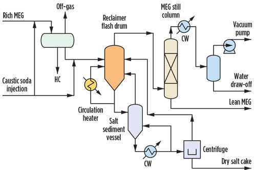
Sufficient residence time is included in the design of the rich MEG vessel, such that three product streams exit the vessel. The hydrocarbon liquids and vapors are directed off-skid to appropriate hydrocarbon handling systems, such as a low-pressure flare or hydrocarbon drain system. The pH-adjusted rich MEG is directed into the Reclaimer Flash Drum.
Vapors exiting the Reclaimer Flash Drum are directed into the MEG Still Column. Both of these vessels operate at sub-atmospheric pressure. This action allows the MEG/water mixture entering the vessel to vaporize at a temperature well below the MEG degradation temperature (about 165°C). Upon flashing into the column, water and MEG will vaporize, while salts and other solids contained in the inlet stream will not vaporize and will, instead, become concentrated in the slurry within the Reclaimer Flash Drum.
MEG/H2O/salt slurry is continuously pumped from the bottom of the Reclaimer Flash Vessel through the Reclaimer Circulation Heater by a horizontal, centrifugal circulation pump. Boiling of the slurry circulating through the Reclaimer Circulation Heater is undesirable as it would result in solids deposition, which would rapidly foul the heat transfer surfaces. Therefore, boiling is suppressed deliberately by imposing a “backpressure” on the heater, using a specific device. In addition, a large circulation rate is maintained through the heater to minimize the temperature rise of the slurry, the skin temperature inside the exchanger, and the time the slurry is in contact with the heat transfer surfaces. Use of these design techniques nearly eliminates the potential of fouling of the heat transfer surfaces, even with divalent cations present.
Upon entering the Reclaimer Flash Vessel, the water and MEG contained in the slurry will vaporize and flow upward through the vessel, while the residual droplets of MEG/H2O/salt slurry fall into the liquid pool in the base of the vessel. As a result, the salt and solids concentration of the liquid
pool increases.
To maintain an acceptable level of solids in the circulation loop, a portion of the MEG/H2O/salt slurry flowing through the recirculation loop is diverted to the solids handling area. A continuous “purge loop” of slurry is pumped to the solids handling system of the plant and back to the reclaimer. Maintaining a continuous flow ensures that solids do not settle in the lines, leading to the solids handling system during low-flow, or intermittent-flow conditions. In this manner, the free solids content in the recirculation loop can be maintained within a tight control band that results in optimal operating conditions for each specific application.
The purpose of the Salt Sediment Vessel is to allow sufficient time for the solids in the process to separate and concentrate before removal from the system. The slurry is removed from the bottom section and directed into the Slurry Cooler and back to the Salt Sediment Vessel. When the solid levels increase to a predetermined set point, a portion of the slurry at the bottom of the vessel is directed off-skid
for disposal.
Vapors that exit the Reclaimer Flash Vessel travel upward through a packed section within the MEG Still Column. These vapors are contacted with reflux water, which is injected at the top of the column. This results in a virtually salt-free Lean MEG product stream that exits the bottom of the MEG Still Column. A distilled water vapor stream exits through the top of the MEG Still Column.
Vapors exiting the top of the MEG Still Column are liquefied in a condenser. The condensed water then enters the reflux drum of the MEG Still Column, where liquid water is separated from any non-condensable vapors and pumped via reflux pumps, either back to the tower as reflux, or off-skid as a Water Draw-Off.
In the Reclaimer, the non-condensable vapors are drawn into a Vacuum Pump and compressed. The bulk of the vent gas stream exiting the Vacuum Pump may then be delivered to the battery limit tie point for discharge to vent or into a LP Flare Header, as required.
OPTIMIZING MEG RECOVERY UNIT
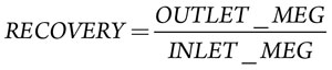
The process design basis (Table 1) provided by the client, has established several performance criteria, which must be met. These criteria include MEG Recovery (>99.5%) and Process Availability (>95%). MEG Recovery is a performance criterion, which is typically established by the client and is determined by Equation 1.
 (1)
(1)
The Inlet MEG has a mass flowrate of 8,724 kg/h. The MEG content in the Desalted Lean MEG product is 8,210 kg/h. Using Equation 1, the calculated MEG recovery is 94.1%. This is below the MEG Recovery dictated in the Process Design Basis. As such, the process must be modified to improve the MEG Recovery.
Glycol is lost from the process through two main exit streams, with the majority lost with the produced salts. In this configuration, the MEG lost in the Slurry Discharge is 514 kg/h. Table 2 shows the glycol losses and recovery for a few different process configurations. To meet the MEG Recovery level of 99.5%, a centrifuge with water wash must be considered. A centrifuge is capable of producing a much drier (less glycol) salt cake stream than what the Salt Sediment Vessel can achieve. To further enhance glycol recovery, a wash step can be included in the centrifuge design. This wash step sprays the dried salt cake with produced water or, recycled brine, if it is part of the process. This action displaces the glycol from the salt cake, reducing the glycol losses to a very low level.
NEXT STEPS
Now that the preliminary design has been completed, and the MRU configuration has been selected, additional details can be developed. Using the process model generated and proprietary equipment sizing procedures, a detailed Equipment List can be assembled. PROSERNAT’s team of engineers and estimators can put together a preliminary cost estimate and can inform the client about the site footprint, weight, utilities requirement and layout.
During the project execution stage, and at the client’s request, PROSERNAT can adopt a flexible approach including license supply, together with basic engineering and some limited proprietary items supply, or the complete modular turnkey unit supply. In both cases, PROSERNAT makes available to the licensee, assistance at commissioning and start-up, and after-sales services, such as regular technical assistance, analysis, training, supply of spare parts, and revamp studies. ![]()
- Advancing offshore decarbonization through electrification of FPSOs (March 2024)
- What's new in production (February 2024)
- Subsea technology- Corrosion monitoring: From failure to success (February 2024)
- U.S. operators reduce activity as crude prices plunge (February 2024)
- U.S. producing gas wells increase despite low prices (February 2024)
- U.S. oil and natural gas production hits record highs (February 2024)

