In this year’s Part 1, we highlight several items related to beam/rod lift systems, motor controllers, plungers, sucker rods, paraffin removal, linear lift pumps, hydraulic jet and piston pumps, and more. We end Part 1 with information regarding pending changes in API’s “Recommended Practice for the Care and Handling of Sucker Rods” (API 11BR).
As mentioned in this feature in May 2013, there are three categories of artificial lift systems: 1) pump-assisted systems; 2) fluid-assisted systems; and 3) flow enhancement techniques. Within these three categories, there are 11 types of lift technologies. In each category, there also exist unconventional or emerging technologies for lift. Table 1 identifies the three main categories and the corresponding methods of artificial lift within each category.
| Table 1. Categories and types of artificial lift systems. |
|

|
Beam/rod pumping is still the most common form of artificial lift. Profiles of several recent developments in rod lift systems follow. First, we provide a reminder regarding considerations for rod pump optimization.
ROD PUMP OPTIMIZATION
Lift system optimization is a fine art that should be conducted at the beginning of any new play. The first objective should be to select a surface unit with enough capacity for the high producing period in a well’s life, but with enough flexibility to operate effectively during the low producing period in the life cycle. Pumping unit optimization includes the proper selection of gearbox size, beam rating, stroke length options and pumping unit geometry.
While overloading a gear box for a short time period may be tolerable, over long periods of time this practice will reduce the gear box life expectancy and is, therefore, not recommended. Due to the implications of a wrist pin failure, overloading the beam or structure of a pumping unit is never acceptable. Doing so may result in the pumping unit flipping over, damaging the wellhead, and possibly endangering human life. The size of the unit and gear reducer is determined by the well depth and the weight of the fluid column, including the rod string weight.
If possible, operators should select a unit that has stroke length options that allow for the high end and the low end of the expected production range. Often, operators purchase surface pumping units with stroke length options longer than necessary. In some cases, the production may drop to the point where producing a well without pounding fluid requires some form of pump-off control. Hence, the range of the stroke length should be considered carefully during the selection process.
Pumping unit geometry also should be considered. If neglected, operators may end up with a pumping unit gearbox that is one to two sizes larger than necessary. There are basically three different beam pump geometry types: conventional, improved and enhanced geometry. Each type results in unique shapes of the permissible load diagram. The unique combination of well depths and production rates in a given field or play will tend to “fit” better into the permissible load diagrams related to one of the three geometry types. This should result in optimal gearbox sizing.
Conventional geometry. Conventional geometry beam pumps are, by far, the most common type of surface pumping unit. Two types of units fall into this category: crank-balanced pumping units (Fig. 1) and beam-balanced pumping units, Fig. 2. These units are often called the “workhorses” of the oil field. If they are properly designed, sized and maintained, they will provide many decades of useful service life.
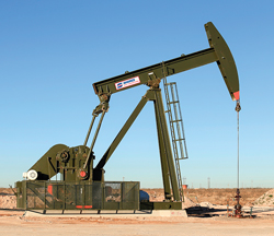 |
| Fig. 1. Conventional crank-balanced pumping unit (courtesy of Shores Lift Solutions). |
|
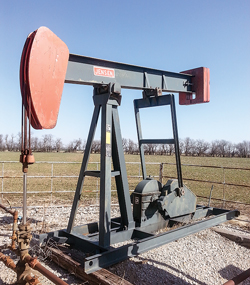 |
| Fig. 2. Conventional beam-balanced pumping unit (courtesy of Jensen Oilfield Equipment). |
|
Both of these units represent a Type 1 lever system, where the pivot (fulcrum) is between the effort and the load. In an off-center Type 1 lever (like a crowbar or pliers), the load is larger than the effort, but it is moved through a smaller distance.
Crank-balanced and beam-balanced surface pumps employ large cast-iron counterweights, placed on the crank arms or on the tail-end of the walking beam, respectively, to provide a counterbalance that partially offsets the well load. This crank or beam balancing helps minimize the torque requirements of the unit’s gear reducer. Torque and power are related. A smaller torque requirement results in less power needed to operate the unit. The correct use of counterbalance allows for a smaller, less-expensive gear reducer and prime mover, as well as less consumption of electricity or fuel. There are numerous manufacturers of conventional surface units and a wide range of sizes from 6.4-28-12 to 1824-305-240.
Improved geometry. There are fewer surface beam pumps that fall into a category often referred to as “improved geometry.” These units usually employ a Type 3 lever system, where the effort is between the pivot, or fulcrum, and the load (like tweezers).
The Mark II Unitorque pumping unit (from Lufkin, a unit of GE Oil & Gas) represents a Type 3 lever design, Fig. 3. According to the company’s catalog, these units are available in 50 different sizes, up to an 1824-427-216. While the Mark II employs crank weights for counterbalance like conventional units, the unique geometry of these units includes three design characteristics that aim to reduce rod load and peak torque:
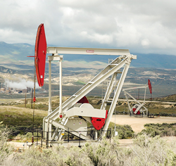 |
| Fig. 3. Mark II Unitorque pumping unit (courtesy of Lufkin Industries). |
|
- Shifting the gearbox from under the equalizer toward the Samson post and the crank arms, turning in a counter-clockwise rotation.
- Placing the equalizer bearing between the horsehead and the Samson post creates a “push-up,” or a Type 3 lever system.
- An angular offset in the crank produces a more effective counterbalance torque.
According to Lufkin, these features, independently, would not produce a relatively uniform torque. However, when they work together, a “uni-torque” system is obtained. This effect can reduce the torque on the gearbox up to 35%, as well as lowering power costs and, often, prime mover size.
Enhanced geometry. Weatherford’s Maximizer II (Fig. 4), the Lufkin RM (the so-called “Reverse Mark”) and the TorqMax from Shores Lift Solutions (a Schlumberger company) all employ enhanced-type geometry and offer benefits typically not found in conventional units. Although similar in appearance to conventional crank-balanced pumping units, the enhanced geometry of these units can reduce the torque and power requirements on many pumping applications. In some instances, a smaller reducer and prime mover can be used. Accordingly, the makers of enhanced geometry units promise to deliver greater productivity at a highly efficient rate.
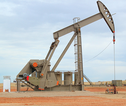 |
| Fig. 4. Maximizer II enhanced geometry pumping unit (courtesy of Weatherford). |
|
Increased efficiencies are achieved by shifting the gear reducer aft to improve the interaction of well and counterbalance torque. Timing of the counterbalance torque is adjusted by angling the crank pin location on the crank arm. These two changes create a pumping unit geometry that yields lower, smoother net torque on the gear reducer and upstream drive elements. Another effect of these design enhancements is that the upstroke polished rod speed is slightly slower than for the downstroke.
Tangible benefits over conventional geometry include:
- Gearbox reducer torque is lower in some cases, allowing for a smaller unit
- Lower horsepower requirements enable the use of a smaller prime mover to reduce lifting costs
- A slower upstroke allows more time for pump fillage.
In contrast to the Mark II design, these units provide more open area around the wellhead for personnel and equipment when workover is required, and they require less energy to lift the same amount of fluid. Enhanced geometry units are available with gear-reducer sizes from 228 to 1824.
Finally, operators should be aware that the first iteration of pumping unit selection and optimization may not result in optimal well performance. As more data become available for a given field or play, the optimization exercise should be performed again, to verify that the lift selection decision is still proper for well/field optimization.
Hardware/software supports system optimization. Theta Oilfield Services’ XSPOC smart automation management system and Spirit Global Energy Solutions’ Genesis Intelligent Asset Manager (both offerings from Dover Artificial Lift, formerly Norris Production Solutions) are two very different products. However, when paired together, they work hand-in-hand to help maximize well performance and increase efficiency through a comprehensive examination of well conditions at field level.
Theta’s XSPOC is a leading, automated, well management software system that uses modern communication channels to link real-time data to powerful diagnostic and design tools. While XSPOC supports many wellhead devices, it is most commonly paired with pump-off controllers.
Spirit’s pump-off controller, the Genesis (Fig. 5), provides operators exclusive technology advancements, including a magnet-mounted laser for precise remote position measurement of the surface pumping unit. The technology dynamically matches the operation of artificial lift equipment to the production from a subsurface formation, extending the productive life cycles of typical artificial lift systems.
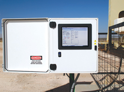 |
| Fig. 5. Genesis Intelligent Asset Manager displays real-time field data. |
|
The ability to pinpoint the absolute position of the surface pumping unit with the company’s pump-off controller leads to more precise data input into XSPOC. Better input data dramatically improves well diagnosis and analysis. An additional benefit of the combined technologies is the animation features that give operators a visual picture of what is going on downhole.
The XSPOC software is distinctive in that the well analysis and data received are in both numerical and narrative or paragraph form. After diagnosis, the resulting data reports advise on pump conditions, fluid levels and many other factors related to well analysis and optimization.
In real time, operators can remotely view an entire production field in a snapshot, while isolating and trouble-shooting potential problem wells. This can result in huge savings of both time and money.
Some software systems require a lot of configuration and management by specially trained personnel; not so with XSPOC. It is truly an intuitive “plug-and-play” tool. Production personnel can take command and make informed decisions as soon as communication is launched, and the system begins to grab key data from various data input points.
In April, Norris Production Solutions (NPS) changed its name to Dover Artificial Lift (see announcement in this issue, on the “Companies in the News” page). The updated brand seeks to better acknowledge the various operating units within the company’s portfolio that specialize in artificial lift, including Spirit Global Energy Solutions and Theta Oilfield Services.
ROD LIFT DEVELOPMENTS
Product profiles of several recent developments in beam/rod pump and linear lift rod systems follow.
Constant speed motor controller. It is estimated that AC electric motors used with surface pumping units or “pumpjacks” consume greater than 70% of the total energy used in producing oil fields. Because increasing electric loads tends to trend in the opposite direction from the net oil recovered, those charged with developing innovative ways to reduce electric power usage have made improving electric induction motor efficiency a top priority.
Induction AC motors typically used on pumpjacks are inherently efficient when fully loaded, but they are very inefficient and wasteful when intermittently or partially loaded. Unfortunately, pumpjack motors are typically operated under intermittently or partially loaded conditions. Consequently, these motors waste energy and place an unnecessary burden on power infrastructures.
Weatherford recently introduced the MotorWise constant speed motor controller (Fig. 6), an AC induction motor energy management and control system. Its patented technology uses the latest Digital Signal Processing (DSP) energy management technology. The units identify partial and intermittent loading conditions and reduce the motor’s voltage to an optimal level. Its operation not only reduces energy costs, it also enables motors to run more smoothly and cooler. This eliminates waste in the form of heat, noise and vibration while maintaining proper operation—collectively decreasing maintenance costs and improving the reliability and longevity of the motor, as well as the pumpjack’s gear box and load bearing components.
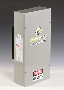 |
| Fig. 6. MotorWise constant speed motor controller. |
|
Running an AC motor below 75% of its rated horsepower is less efficient and thus wastes energy. It is not always possible to match the application to the rated load of the motor. In the AC circuit for a pumpjack motor, power is used most efficiently when the current is aligned with the voltage. The loads vary considerably, so this new DSP controller is very fast while dynamically controlling the energy being used by the motor. If a sudden increase in loading occurs, the controller can increase the voltage quickly, to match the motor power requirements without stalling. It also dynamically sets the optimal voltage or energy setting many times per second.
Generally, on each stroke of a pumpjack, there are two moments where the balance of the motor moves from fully loaded to a light load or even a negative load, where the motor actually acts as a brake or a generator. The controller senses when the motor is very lightly loaded and will actually turn off the motor for a very short period. To achieve that obvious, significant reduction in energy usage, the DSP controller has sophisticated algorithms to determine when/if to turn off the motor safely. The off time corresponds to the braking period, when the motor is being overhauled by the counterweights. This technique has made dramatic efficiency improvements in the continual loaded and unloaded phases of pumpjack motors.
MotorWise energy-saving motor controllers are specifically designed for three-phase motors (up to 100 hp) used on oilfield pumpjacks. They are compatible with conventional, improved and enhanced geometry pumpjacks. They are used in a variety of three-phase power distribution schemes, including wye, delta and grounded-delta configurations.
Depending upon the application, the manufacturer states that these controllers can improve the efficiency of an induction motor immediately, by as much as 25%. They employ a proprietary soft-start motor algorithm to reduce the daily wear-and-tear caused by the many start/stop operations. This can improve the life of the motor significantly, as well as that of the gear box and belts connected to the motor. The soft-start feature also reduces the high-demand penalty cost charged by utility companies.
MotorWise motor controller’s wall- or pole-mounted design is easily installed between the power mains, with or without a rod pump controller (RPC) and no other needed equipment. Its rugged design allows placement in the harshest environments, and a variety of models are available to best suit the size of the pumping unit.
Its autonomous no-service operation enables years of trouble-free operation. Current installations have resulted in 15% to 25% reductions in actual electrical energy costs, while seeing improved reliability and less production downtime. Many users are reporting 15-to-18-month payback, as their pumping units now run quieter and the need for electric motor maintenance has been reduced.
New plunger adaptor. Formation solids in a well are always a problem with rod pumping. Since hydraulic fracturing has become routine in shale wells, increased sand or proppant from the procedure only serves to amplify the problems. Hence, a common method for dealing with solids in the well is to use the cheapest plunger pump available, assuming it won’t last long in such a hostile environment.
Formation solids and frac sand will shorten the life of any downhole plunger pump. When sand enters between the plunger and barrel, sand cut allows slippage that gets worse over time from fluid erosion. Addressing this common problem typically consists of adding various accessories, adjusting plunger fits, implementing chrome barrels, or using specialty plungers (grooved-body, hardened, FARR, etc.). With this in mind, anything that extends rod pump runtimes and delays pulling crew expenses for even an extra day of production is desirable.
In continuing attempts to extend plunger pump runtimes, Don-Nan’s new patented Sand Diverter plunger adaptor (Fig. 7), has caught the attention of several Permian basin operators. This new plunger adaptor comes with the same spray-coating that Don-Nan plungers receive for extra durability and longevity. When coupled with a tapered seal plug on the bottom of the plunger, this assembly literally diverts sand and solids through the plunger, thus minimizing any sand cut between the barrel and plunger.
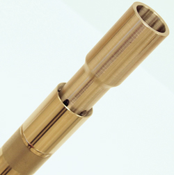 |
| Fig. 7. Sand Diverter adaptor attached to a plunger. |
|
Rick Roderick, technical advisor for Don-Nan, says “the FARR plungers have done really well for us, but we ran into limitations when it came to a lot of the new drills, where the average well depth was putting us at 10,000 ft. The plunger wall of the FARR wasn’t holding up as long (as a regular plunger) with the immense pressure of the fluid column in deeper wells.”
By creating a plunger adaptor with a larger spray-coated outer diameter, all downhole fluid flow and solids are directed through the plunger instead of travelling between the plunger and barrel. Standard plunger adaptors have a smaller base than plungers, which allows particulates of all sizes to form around the base of the plunger adaptor. Once the plunger is stroked, sand cut ensues on both the plunger and barrel.
To delay damage, the use of a chrome coating can help protect the barrel against sand-cut, but even chrome becomes problematic if the downhole environment is highly corrosive and requires any acidizing. Alternatively, operators can opt for specialized plungers at various costs to extend plunger life. “In either of these cases, the risk of altering the largest components of the pump can weigh on operators’ minds hoping the runtime extension will justify the added expense,” Roderick said.
James Idell, Laredo Petroleum production foreman, echoed this when he said, “I’ve tried grooved body plungers, pressure-actuated plungers…everything. The Sand Diverter has really worked well for us. There are a couple of products that work well, but they are usually more expensive. This one seems to have some longevity to it. Recently, we had to pull a well, due to a rod part or a tubing leak, and we pulled the pump out that had a Sand Diverter in it. We noticed that, even with all the sand down there, that the pump was going to last longer, since it was protecting the plunger better.”
Premium sucker rods. Tenaris’ BlueRod premium sucker rod (Fig. 8) incorporates an innovative rod connection thread specially designed for higher loads and extremely deep wells. This new technology is designed to improve the rod’s fatigue life and promote pumping efficiency. These and other benefits make the rods fit for challenging shale operations, where beam pumping is required.
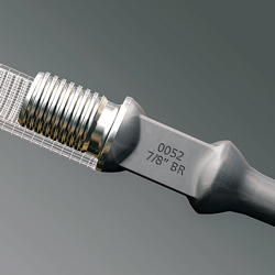 |
| Fig. 8. BlueRod premium sucker rod. |
|
The product’s main features include:
- Tapered trapezium thread profile
- Diametrical interference with flank-to-flank contact
- Improved stress distribution along the thread profile
- Higher load capacity, due to reduced pin make-up pretension.
Shale wells are characterized by multiphase flow regimes, deep pump seating, high deviation and steep production declines over time. In the first stages of oil production, shale plays have high production rates, due to high reservoir energy, so hydrocarbons flow naturally up the wellbore to the surface. However, depletion rates are high. When the energy decreases, and the pressure is not enough to lift the fluids, artificial lift systems come into play. At the beginning, transitional methods, such as electric submersible pumps (ESP) or gas lift, help operators maintain the level of production, but it soon becomes necessary to use another form of artificial lift. Beam/rod pumping (reciprocating pumping) is the most common option at this stage.
When a reciprocating pumping system is installed in shale applications, the sucker rods face several challenges simultaneously.
The use of 23/8-in. diameter tubing strings is widely extended in shale installations. Thus, a 7/8-in. slimhole coupling is the larger diameter available to be used in the tubing string, limiting the size of the rod that can be used.
Conventional rods are limited in the maximum cyclic load that they can withstand, and this impacts the system’s pumping and production capabilities. Also, because of the deviated geometry of most unconventional wells, molded guides must be added in the sections with high dogleg severity. The contact of the guides with the tubing increases the load in the sucker rod above the contact zone, so the improved fatigue resistance of special connections becomes essential for these applications. In addition, corrosion prevents the use of high steel grades that provide superior resistance to cycling loads.
Under these conditions, the conventional sucker rod connection becomes the weakest point of the installation. Standard connections have uneven stress distribution along the thread profile and, therefore, present high stress concentration zones. They have a tendency to back off and show increased risk of being easily over- or under-torqued. Since conventional rod connections were not designed to handle extreme loads, operators frequently face premature connection failures.
These premium sucker rods were developed to overcome conventional connections’ design limitations. The flank-to-flank contact decreases the tendency to loosen, because it eliminates the gap present in the conventional thread profile and increases the interference level. Their tapered trapezium thread profiles with diametrical interference reduce the pre-tension stress in the pin make-up, increasing fatigue life. In addition, the lower displacement during make-up and uniform contact between the flanks allows a better stress distribution and reduces the permanent deformations created in threads during both make-up and operation.
Due to these features, BlueRod premium sucker rods provide a wide number of benefits. They expand the traditional working capacity of the rod pumping system to operations that are normally restricted to ESPs; improve performance in high-load operations by using a lighter rod string composed of sucker rods with smaller diameters; and reduce the stress level, together with the energy consumption in the surface pumping unit. In addition, premium sucker rods with 4320 KD steel grade perform in mild corrosive environments with significant mechanical loads, where standard high-strength rods usually would be required. These benefits are aimed at reducing the number of workover operations needed, due to sucker rod failures.
Paraffin abatement system. It is estimated that rod rotators can extend the life of rod guides by 400%. Weatherford has combined its straight-vane rod guides with its Intelligent Rod Rotator (see World Oil, May 2013) as a paraffin abatement system. The result of this equipment combination not only extends the wear-life of rods, but it also clears paraffin build-up on the full internal circumference of the tubing, Fig. 9. When the rod guides are spaced closer than the stroke length, virtually the entire tubing length is cleared of paraffin build-up. The ultimate result is increased production through a reduction in downtime and operating cost savings, by reducing the time and resources required for rod-pulling jobs.
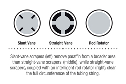 |
| Fig. 9. Slant-vane scrapers (left) remove paraffin from a broader area than straight-vane scrapers (middle), while straight-vane scrapers coupled with an intelligent rod rotator (right) clear the full circumference of the tubing string. |
|
Conventional sucker rod rotators evenly distribute wear around the rods and couplings, rather than limiting the wear to one side. They also can be coupled with paraffin-clearing rod guides. However, a non-functioning rotator reduces the effectiveness of the guides in clearing paraffin and does little or nothing to extend rod life. That is why this system incorporates an internal rotation sensor and a built-in, anti-rotation mount that takes the guesswork out of rotator failures and reduces the likelihood of lost production.
The sensors quickly alert operators to rotator failure, potentially saving weeks of declining production and downtime. That way, the operator knows right away when the rods have ceased rotating, rather than waiting for a pumper’s report, which can be unreliable and untimely,
at best.
This paraffin abatement system is an affordable, durable solution that seamlessly integrates with existing rod-pump controller systems. The system can be integrated with Weatherford’s WellPilot rod pump optimization controller and LOWIS real-time optimization software for a comprehensive rod pump optimization system.
LINEAR LIFT PUMP DEVELOPMENTS
As previously mentioned, sucker rod pumps occasionally encounter solid particles or debris during operation. Often, these solids pass harmlessly through the pump, but sometimes the pump travelling and/or standing valves become stuck or will not properly seat, causing the pump to malfunction.
Occasionally, the debris will dislodge or clear as a result of normal operation of the pump, and no intervention is required. Other times, it is necessary to flush or pull the pump. Some operators may attempt a “bump down” procedure, where the pump and rod string are dropped from a short distance in an attempt to dislodge the debris through the shock of the pump plunger striking the bottom.
LRP “Pump Clean” feature. Unico’s LRP linear rod pumping unit (Fig. 10) employ a Pump Clean mode, in which the pump vibrates at strategic frequencies for approximately two minutes to dislodge the trapped debris. This action can be executed in one of three ways: remotely, at the drive keypad or automatically.
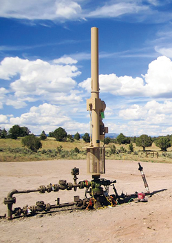 |
| Fig. 10. Unico LRP linear rod pumping unit. |
|
The LRP system consists of a reversing motor coupled to a rack-and-pinion mechanism. The reciprocating action of the rack actuates the rod string via a traditional rod clamp atop the rack. The inverter drive has embedded well optimization software that controls the operating parameters as a function of measured and predicted dynamometer analysis.
When a pump valve is stuck open, the drive’s generated downhole dynamometer graph will go flat. More specifically, if the traveling valve is stuck open, the effective downhole dynamometer load will be stuck near zero, as the pumping unit is merely raising and lowering the weight of the rod string. Conversely, if the standing valve is stuck open, the effective pump load will be stuck near the theoretical fluid load as the unit is raising and lowering the weight of the rods, plus the fluid.
The company’s GMC remote global monitoring control system immediately notifies the operator of a stuck valve condition, at which time the Pump Clean algorithm may be executed. Alternately, the algorithm can be programmed to execute automatically, once per day. Multiple executions may be required, depending upon the severity of the clog. In severe cases, traditional flush by methods are required.
Figure 11 shows the dynamometer trend before and after a Pump Clean mode on a well in southern Illinois. The data were collected by the LRP drive and reported, using the GMC remote well monitoring tool. The operator was alerted to the pump problem by the GMC summary trend, Fig. 12. The estimated bpd had dropped to zero, the pump fill was a negative two (-2) (indicating no fluid lift), and the pump load was zero. After running the Pump Clean mode, the pump fill returned to 100%, and the pump load was restored. Pump Clean mode has the potential to reduce downtime and maintenance costs, and as such has become a commonly used feature in the LRP system.
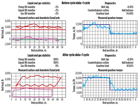 |
| Fig. 11. Drive dynamometer plots before (top) and after (bottom) Pump Clean. |
|
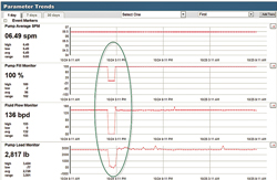 |
| Fig. 12. GMC remote monitoring summary trend, showing the stuck valve episode and subsequent Pump Clean results. |
|
Using predictive modeling to manage sucker rod dynamics. In sucker rod-pumped wells, rod dynamics comprise overshoots and oscillations in rod loads occurring from acceleration forces associated with reciprocation of the rod string mass. Sucker rod dynamics often contribute to problems, such as premature rod breaks, rod fatigue and rod box/tubing wear caused by rod buckling.
In recent years, improved rod string designs, and better rod and coupler materials, have increased the longevity of downhole equipment. However, little effort has been made to address a major contributor to downhole wear—the motion profile of the surface pumping equipment.
The motion profile of a beam/rod pumping unit is fixed by its geometry and crank speed, irrespective of particular well characteristics. Rod velocity and acceleration are dependant variables governed by the rotational speed of the crank. The resulting motion profile may or may not be best suited for a particular well.
Unico’s LRP system, by design, allows more degrees of freedom with independently adjustable velocity, and acceleration rates and variable profiles. Low inertia mechanics allow for a responsive, adaptive speed control. Servo motion profiling and closed loop damping algorithms manage resonant loads, allowing direct control of the downhole pump, much like a robotic end effector. Downhole equipment is protected better by attenuated peak loads and increased minimum loads.
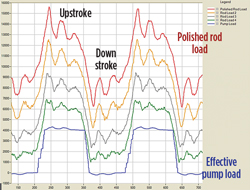
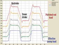
To demonstrate the effect of sucker rod dynamics on the pumping system, a conventional Class I crank-balanced unit and a Unico LRP unit of identical stroke length were simulated. Average pumping speed was identical. The reservoir inflow, pump action, rod string behavior, surface pumping equipment, and motor/drive response was simulated using industry-accepted predictive modeling techniques.
In both cases, the pump stroke was 100 in. Average pumping speed was 6 strokes/min. The well was 5,000 ft deep, with a 1.5-in. pump. The rod string was tapered: 0.875-in. diameter for 3,000 ft and 0.75-in. diameter for 2,000 ft. The conventional unit was running at a fixed crank speed. The LRP unit incorporated an active damping control.
To demonstrate the rod damping effect along the entire rod string, Figs. 13 and 14 illustrate rod string loads from surface to pump (at various points down the length of the rod). Figure 13 shows the conventional unit. Figure 14 shows the LRP unit. Effective pump load convention is used (i.e., buoyancy is ignored).
 |
| Fig. 13. Rod string load distribution with conventional pumping unit |
|
 |
| Fig. 14. Rod string load distribution with LRP rod load damping. |
|
The rod damping case shows a considerable reduction in rod dynamics along the entire string. Peak polished rod load is reduced. Minimum polished rod load is increased, reducing rod buckling potential by decreasing the length of rod subjected to compression (by lowering the neutral stress line). The undershoot in rod load with a conventional pumping unit causes the neutral stress line in the rod string to be raised. This causes a longer length of rod to be subject to compression. If the length exceeds the critical buckling point, obviously the rod will buckle. Hence, there is an advantage to shortening that length.
There are other advantages to surface motion profiling. For example, a “soft landing” feature can reduce the speed of the downhole pump just prior to fluid impact, once again reducing the buckling tendency by lowering the neutral line. In a similar fashion, peak upstroke pump speeds can be limited to reduce viscous flow pressure drop across the pump intake.
HYDRAULIC JET PUMP DEVELOPMENTS
Hydraulic jet pumps are an effective way to remove fluids from a wellbore. Jet pumps utilize the Venturi principle, converting high-pressure fluid to a low-pressure, high-velocity stream, which draws in the formation fluid. The power fluid and formation fluid commingle inside the throat and move through a diffuser increasing the pressure for lift. To operate effectively and without cavitation, the jet pump requires a certain amount of inflow or suction pressure, depending on the required lift. In a wellbore, the inflow pressure directly correlates to the fluid level above the pump. Depending on the depth of pump, the pump intake pressure required could be significant, which in some instances is not available, due to poor wellbore pressure.
Multi-stage jet pump. Accelerated Production Services’ patent-pending, multi-stage jet pump design utilizes one smaller jet pump combination to discharge into the suction of a larger jet pump combination, Fig. 15. The smaller stage can handle lower pump intake pressure, in turn reducing the possibility of cavitation. With the increased pressure from the first stage’s discharge, the second stage can use a large combination to lift fluid to surface for wells that were not candidates previously, due to their low wellbore pressure.
 |
| Fig. 15. Multi-stage jet pump schematic. |
|
Tests were recently conducted in a controlled setting under lower pressures than a typical jet pump would operate. Results varied with some multi-stage jet pumps outperforming their corresponding single-stage jet pump, while some underperformed, showing no improvement. The tests proved that the multi-stage jet pump can lower the pump intake pressure further than the single jet pump, because it uses a smaller throat and nozzle combination to create the lower-pressure area.
The tests concluded that the two-stage jet pump can outperform the single stage in drawdown, if sized correctly. The multi-stage jet pump should open the application window for jet pumps, as a whole. It retains the main advantages of a typical single-stage hydraulic jet pump: no moving parts; hydraulically retrievable; easily adaptable to changing well conditions; tolerates solids; and can be repaired at the well site, if necessary.
HYDRAULIC PISTON PUMP DEVELOPMENTS
The concept of dewatering natural gas wells with hydraulic pumps continues to evolve as a viable artificial lift technology. Gas market prices and production experience are stratifying the application ranges of dewatering technologies. Hydraulic dewatering is a desired solution, at the point in a well’s life where added energy lifts water to the surface, and does not rely solely on the well’s energy. The concept of using hydraulic power to lift wellbore fluids is not new. In fact, it dates back to the early part of the last century. To a large degree, economics have kept the concept from broad market acceptance.
Retrievable hydraulic piston pump. Cormorant Engineering has focused on developing hydraulic dewatering technology since late 2008. The company has developed and deployed multiple products to address a wide range of needs, including depths to 10,000 ft and water production volumes up to 150 bpd. The ability to deploy these units via coiled tubing (CT) extends the technology beyond vertical wellbores to horizontal wellbores, up to a 25°+ dogleg severity.
In the past, the cost of multiple-string coils, the cost of CT rig time for deployment, and the cost of rig time for pump replacement, coupled with recent gas prices, has made it difficult to profitably dewater some gas wells.
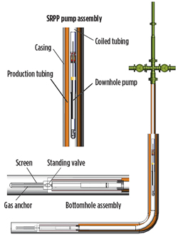
However, a new product and concept—the SRPP (self-reciprocating production pump)—was introduced at the recent Denver ALRDC Gas Well Deliquification conference, which addresses most, if not all, of the economic and technical challenges of hydraulic dewatering. The SRPP is made up of three basic parts, as described below.
The pump–The pump is powered by pressurized wellbore fluid. It contains a new ceramic-based valve system for directing the pressurized fluid. It sits in the BHA and is held in place by the pressurized wellbore fluid above it. The SRPP is deployed and retrieved, simply by pumping the unit, to and from the surface, through the attached coiled tubing string. It is received at the wellhead in a typical API lubricator/catcher and at the bottom of the string in the BHA housing.
Bottomhole assembly–The bottom-hole assembly (Fig. 16) consists of a housing, which sits in a conventional pump-seating nipple and attaches to a coiled tubing string.
 |
| Fig. 16. SRPP completion detail with BHA, coiled tubing and wellhead. |
|
Surface power unit–The power for the downhole pump is provided from the surface unit by recirculation of some of the produced wellbore fluids. A hydraulically driven, conventional rod pump supplies a continuous flow of pressurized fluid. The fluid flows through the CT, drives the downhole pump and is comingled with produced fluids in the production tubing/CT annulus, then flows to the surface. There are no complex controls to operate, simply an on/off switch and variable-speed drive. The system is optimized easily by field personnel.
The initial investment and cost of installing the SRPP are substantially less than a rod pump system, which is the most common baseline for comparing artificial lift systems. Essentially, this complete system can be installed, including the CT, well head modifications, CT services, pump, surface unit and initial pump deployment, for less than the cost of a conventional rod pumping unit, without considering the cost of workover, cost of rods, etc. A typical installation requires one day for a well with production tubing installed and a landing nipple.
The downhole pump can be replaced with a new or rebuilt pump. Using the SRPP surface system, simply pump the downhole unit from the wellbore, and then pump the new unit into place with the same surface system.
Due to the very low cost of deployment and retrieval, any material, corrosion and configuration changes can be made quickly and inexpensively, reducing any learning curves for a given well by orders of magnitude.
Liquid rod pumping system. Although not a piston pump, the Liquid Rod Pump (from the Liquid Rod Company LLC) is a form of hydraulic pump designed to increase efficiency without the use of sucker rods from the surface unit to the downhole unit, hence the name. The potential cost savings of no sucker rods allows for marginal wells that may have been abandoned prematurely, due to high energy and maintenance costs, to be returned to profitable production.
With no moving parts between the surface unit and the downhole unit, the pump can operate equally well in vertical, deviated or horizontal wells. The pump can be installed much like a traditional insert pump with a power fluid string of smaller tubing run inside standard 23/8-in. or 27/8-in. tubing. The smaller tubing allows for the transfer of the power fluid, while creating an annular space within the tubing for production. The insert pump allows for the entire pump to be pulled without pulling the tubing. This design also allows for simultaneous injection into a disposal zone that may be located either above or below the active producing zone.
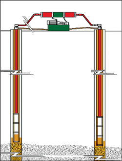
The power drive system on the surface is a closed system of hydraulic fluid that does not co-mingle with the power fluid (water) or production fluid. The surface unit, consisting of the power pack and the pulsar, can be installed at or below ground level, where it is not visible from the surface, allowing the appearance and contour of the terrain to be maintained.
One test installation utilized a single surface unit to pump two separate wells—a new concept in pump technology, Fig. 17. The two wells were approximately 5,000 ft deep and 3,500 ft apart. A 15-hp motor was used in this application, with insert-style pumps, to achieve volumes of approximately 140 bpd. It is projected that the technology can be utilized at much greater depths, and the tubing pump design can be utilized to achieve much greater volumes.
 |
| Fig. 17. The Liquid Rod Pump surface unit can be used to pump multiple wells. |
|
OTHER DEVELOPMENTS
In 2008, CJS Production Technologies developed a vertical umbilical product, called FlatPak, to simplify the installation and actuation of hydraulic pumping systems (see World Oil, May 2013).
ArmorPak umbilical. In the fall of 2013, CJS expanded its umbilical technology to include ArmorPak, an all-metal umbilical solution for deeper depth and thermal applications. ArmorPak is a dual coiled tubing umbilical (Fig. 18), intended to install hydraulic (Fig. 19) and electric pumps (Fig. 20). It also is used in conjunction with a modified hydraulic jet pump for use in wellbore cleanout applications, Fig. 21.
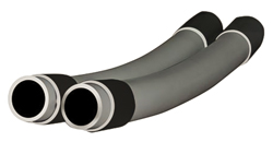 |
| Fig. 18. ArmorPak dual CT umbilical. |
|
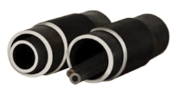 |
| Fig. 19. ArmorPak triple CT umbilical with injection capillary conduit and data transmission cable. |
|
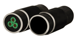 |
| Fig. 20. ArmorPak with 3-phase electrical cable. |
|
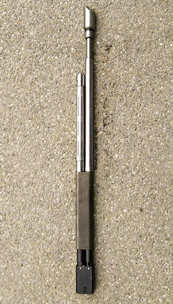 |
| Fig. 21. Modified jet pump used with CJS umbilical to perform wellbore cleanouts. |
|
ArmorPak is manufactured in Canada by CJS. Specialized processes for assembling the umbilical, combined with a novel suspension system used in the CT injector, were developed by CJS to offer this technology. Additional developments connected to ArmorPak include a specialized stripper and BOP system to facilitate live-well ArmorPak installation. ArmorPak, like FlatPak, can be configured to include injection capillary conduits, along with data transmission cables.
When a closed-loop hydraulic circuit is required to power a downhole pump, such as the company’s HydraPak PCP or HydraPak HSP, installing a third tube into the hydraulic side of the dual-umbilical permits injection and receipt of hydraulic motor fluid through the concentric side to power the pump.
ArmorPak also can be configured to install, and act, as the carrier of electric power to function an electric submersible pump, where one coil is pre-loaded with electric cable to power the downhole ESP.
ArmorPak can be utilized at any depth, and under any wellbore conditions previously validated by conventional coiled or jointed tubing.
Pending change in API RP 11BR. API is updating the “Recommended Practice for the Care and Handling of Sucker Rods” (API 11BR). One of the changes under consideration is updating the Modified Goodman diagram, based on current industry practices and recent manufacturer testing. If this change is approved (which is highly likely), the design of rod strings will undergo significant changes.
The Goodman relation is an equation used to quantify the interaction of alternating stresses on the fatigue life of a material. Sucker rods do not simply undergo a single load or stress; rather, they cycle between a maximum load (stress) and minimum load (stress) several times in a day. This cyclic loading of a sucker rod will fatigue the metal and, with time, result in a failure at a load or stress lower than the maximum tensile strength rating of the metal.
In the late 19th century, both J. Goodman and W. Gerber developed equations/graphs that showed the relationship of failures due to cyclic loading. They both used experimental data, plotted as mean stress versus peak stress-at-failure. The resulting diagrams were a plot with a y-axis of tensile strength versus an x-axis of stress containing three lines (maximum stress, mean stress and minimum stress versus tensile strength), Fig. 22.
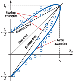 |
| Fig. 22. J. Goodman and W. Gerber developed equations/graphs that showed the relationship of failures, due to cyclic loading. |
|
As more data became available, the minimum stress line was dropped from the Goodman diagram. This resulted in a modified Goodman diagram, with a straight line relationship of maximum stress and mean stress versus tensile strength to allow for infinite-life in a noncorrosive environment, Fig. 23. As illustrated, the lower stress limit intercepts zero stress and zero tensile strength, and is a straight line with a slope of one, ending at a tensile value equal to the tensile strength of the metal. The upper stress limit intercepts the vertical line at a value T/2 (tensile/2), with the second point of the straight line being at the intersection of the lower stress limit, at a value of T.
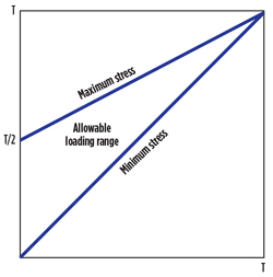 |
| Fig. 23. Original Goodman diagram. |
|
In the 1960s, API adopted the Modified Goodman diagram to account for the corrosion, abrasion and bending moments that are common in an oil well. There had been very little testing done, and limited, documented field data existed. The committee decided to modify the diagram by reducing the y-intercept to T/4 and to change the slope of the maximum allowable load from T to T/1.75. A comparison of the original Goodman diagram and the API Modified Goodman diagram is illustrated in Fig. 24.
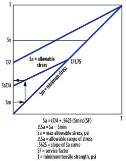 |
| Fig. 24. API Modified Goodman diagram. |
|
Over the years, as well depths increased, rod loading began to increase to points where API D rods were being loaded beyond 100%, per the API Modified Goodman diagram. Since API D rods represented the highest tensile/strength rods available at the time, manufacturers developed new “high-strength” rods. These new rods were not API-recognized and, therefore, were not limited to the API modified diagram. Manufacturers of high-strength rods modified the Goodman diagram and instead of T/4, the y-intercept was increased to T/2.8 (more conservative than the original Goodman diagram but less so than the API Modified Goodman diagram).
As the industry started using more of the high-strength rods, it became evident that the higher-strength material was more notch-sensitive, and failure rates in some corrosive environments were much higher than desired. Along with the fact that T/2.8 was being used successfully in non-corrosive environments for high-strength rods, various producers began pushing the API D and KD rods beyond the API Modified Goodman diagram. The early results were favorable, and failure frequencies in certain corrosive environments improved, even though the API D rods were being designed with service factors as high as 1.35.
The current Task Group working to update API Spec 11B—“Specification for Sucker Rods”—has decided to adopt high-strength rods as an API recognized grade. This can help ensure producers that they are receiving rods that meet physical, chemical and dimensional properties necessary for quality control. During the Task Group’s review process, the need to standardize on one Modified Goodman diagram became evident, and several producers suggested that the less conservative value of T/2.8 be used for all grades of API rods. At least one manufacturer conducted fatigue tests at a load that indicates T/2.5 could be used without any concerns about pure fatigue failure.
Therefore, the new, proposed, Modified Goodman diagram for the next release of API Spec 11BR will use T/2.8 as the y-intercept and T/1.75 for the maximum allowable load. Once the document has passed ballot and is adopted by API, all design software should begin incorporating these values for all grades of API rods. The expected release date is the fourth quarter of 2015. 
|


