Continuing last month’s “What’s new in artificial lift?” discussion, this report covers recent developments in the areas of electric submersible pumps (ESPs), progressive cavity pumps (PCPs) and plunger lift developments.
The method used in choosing an artificial lift system is too often a “we’ve always done it this way” decision process, rather than a strategic plan based on thorough operational and cost analyses. Hence, before profiling several product developments, we want to underscore yet again the importance of proper lift system selection.
To that end, Weatherford provided us a recent case history involving what might typically have been an ESP application. However, upon analysis, the operator determined there was a good alternative.
ESP vs. LONG-STROKE ROD PUMP
In the oil field, conventional wisdom holds that the rod lift artificial lift method is suitable for wells producing at rates of 200 bpd or less. Of course this is heavily dependant on the depth of the well and weight of the fluid column. So, under the right conditions, some might put this rate as high as 400 bpd or even 600 bpd.
However, most low-rate ESPs (up to 1,000 bpd to 1,500 bpd) feature low efficiencies compared to higher rate ESPs. This can result in increased power costs and reduced runlife. From a cost structure perspective, the bulk of ESP system costs are concentrated in the downhole equipment, which generally can have a lower runlife compared to surface-centric lift systems. Hence, investing in an ESP system might appear to be riskier than investing in alternative lift methods, whose cost structure is concentrated in the surface equipment with a runlife of 20 years or more.
Like conventional beam/rod pump systems, long-stroke pumping units employ sucker rods connected to a downhole pump. However, the surface equipment is fundamentally different for the long-stroke unit, as the pumpjack is replaced with a vertical unit that is shipped and installed at the wellsite in one piece, Fig. 1.
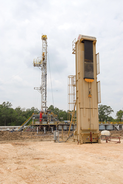 |
| Fig. 1. The Weatherford Rotaflex long-stroke pumping unit (foreground). |
|
As its name implies, when compared to a beam pumping unit, a long-stroke system has a longer stroke length. These units also operate at fewer strokes or cycles per minute (an average of 3.75 strokes/min. vs. an average of 8 strokes/min. for conventional surface pumps). During a large part of its pump cycle, the long-stroke unit’s rod string moves at a relatively steady velocity. This results in fewer acceleration-deceleration cycles and fewer rod reversals.
Long-stroke units use a torque arm with a shorter radius than the distance between the saddle bearing and the horsehead on a beam/rod unit. This transmits power at a lower torque, and extends the applicability of the long-stroke unit to a wider range of production rates and well depths.
For well servicing, after disconnecting the bridle and carrier bar from the polished rod, the long-stroke unit is rolled away from the wellhead without any further disassembly. When a workover is completed, the unit is rolled back into place, and the carrier bar is reconnected to the polished rod. Hence, the long-stroke units often can provide simpler well servicing.
Long-stroke units routinely achieve up to 1,500 bpd at 6,000 ft (1,800 m) and 100 bpd at 10,000 ft (3,000 m). In shallow wells, which are typically non-ESP applications, long-stroke units can deliver production rates exceeding 4,000 bpd, Fig. 2. In some cases, they can provide greater operational efficiency than ESPs at similar depths.
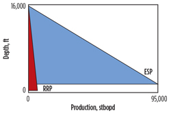 |
| Fig. 2. General operating ranges for ESPs vs. reciprocating rod pumps (RPP). |
|
While ESPs can be prone to premature failures, a long-stroke’s downhole rod pump is usually more tolerant to extreme downhole conditions.
In this case history, a mature oil well provided an opportunity to compare operating expenses (OPEX) of an ESP and a long-stroke pumping unit. The well’s production had slowly declined from an initial rate of 3,000 bpd to less than 1,200 bpd. The existing ESP pump was nearing the end of its operating life and running at 30 Hz in a down-thrust condition. The operator was forced to replace the downhole lift system ahead of imminent ESP failure. The well parameters for the evaluation process are shown in Table 1.
| Table 1. Well parameters for the candidate well. |
|

|
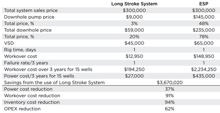
Both lift systems in this geographic region have essentially the same sales price, but the overall OPEX associated with the ESP is $3,670,020 higher, Table 2.
| Table 2. OPEX comparisons for the ESP and the long-stroke pumping unit. |
|
|
The reason for the significant OPEX difference is in the price breakdown of both systems. For the long-stroke system, total downhole price comprises the cost of the rod pump and sucker rods, while the ESP price comprises the downhole pump assembly (multi-stage centrifugal pump, intake, protector, motor and power cable).
Focusing on the long-stroke system, the $9,000 represents the price of the downhole reciprocating rod pump. The total downhole price represents the price of the rod pump plus the sucker rods ($9,000 + $50,000 = $59,000). For the long stroke system, the cost of the variable speed drive (VSD) represents only the price of the drive, since a step-up transformer is not required.
For the ESP, $145,000 represents the price of the downhole pump, intake, protector and motor. The total downhole price ($235,000) includes the downhole assembly ($145,000) plus the power cable ($90,000). The VSD price includes a load filter and a step-up transformer.
Additionally, the workover cost for the ESP is 91% higher than for the long-stroke unit. Workover costs include rig rental cost, cost of deferred production and the replacement price of a downhole pump.
OPEX is estimated as a sum of workover cost (assuming a reasonable rate of one failure per three years), power cost for three years, and the cost of three downhole pumps used as inventory for an oilfield consisting of 15 such wells.
For the ESP, for example, this works out to $2,234,250 (workover cost over three years for 15 wells considering run life of three years per well) + $3,271,860 (power cost of ESP wells in this region for a life span of three years) + $435,000 (three ESP pumps at $145,000 each).
This exercise demonstrated that the long-stroke pumping unit could provide significant financial benefits in wells that were traditionally considered to be low- and medium-flow ESP applications. While both the ESP and the long-stroke pumping unit can deliver a 1,180-bpd production rate, the OPEX associated with the long-stroke unit proved lower, due to benefits in three major areas:
- Power cost reduced 37%
- Workover cost reduced 91%
- Inventory cost reduced 94%.
This case history provides a good example of artificial lift system selection. For a more detailed discussion regarding artificial lift system selection, refer to SPE paper 52157 entitled “Selection of Artificial Lift” by James Lea and Henry Nickens. Also, more useful system selection information can be found in the Petroleum Engineering Handbook, Volume IV: Production Operations Engineering.
ESP DEVELOPMENTS
An ESP downhole assembly will typically include the electric submersible pump, a gas handler/separator or standard intake, a seal section, a submersible motor with a connected power cable that runs to the surface, and often a downhole sensor package that communicates pump and wellbore performance information back to a surface interface system. The surface equipment may include a VSD or switchboard, a motor protection system and/or an intelligent control system. This year, we feature several submissions related to ESP systems.
High-efficiency ESP motors. Summit ESP has released a new line of motors, dramatically increasing horsepower per rotor, efficiency and performance over legacy design motor technology. The new Corsair motors (Fig. 3) in both 456 series and 562 series have several distinct advantages that allow for increased horsepower ratings along with reduced operating temperatures, promoting reliability and extending run life.
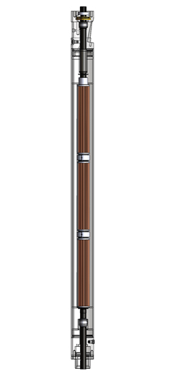 |
| Fig. 3. Summit Corsair high-efficiency ESP motor. |
|
In these new motors, Summit has eliminated the recessed rotor, which required motor bearings to be inserted into the rotor increasing friction, reducing cooling exposure and increasing heat to the system. Eliminating the recessed rotor allows for utilization of a wider motor bearing facilitating better heat transfer and internal cooling properties.
The new motors offer positive locking bearings that are non-magnetic, which eliminates concerns of bearings operating outside of the brass lams used in other motors. Additionally, the motor shaft has added lubrication slots for each bearing. This improves lubrication between the bearing and sleeve and reduces internally generated heat and wear.
The motors employ coffin-shaped rotor bars (which increase the copper content by 22%), closed slot all steel stator laminations and double-wrapped polyimide insulated windings. For extreme temperatures the double-wrapped polyimide windings can be extruded with patent-pending Peek insulation, which provides the benefits of the insulation’s higher temperature rating and maintains the advantages of the polyimide’s dielectric strength.
Improved seal section. As previously mentioned, major downhole components of an ESP system are an electric motor, seal section, pump intake and centrifugal pump. The motor is designed to operate in well fluid and is generally protected from well fluid ingress by means of a seal section that is bolted directly to the top of the motor. The seal section provides four main functions: 1) provides a fluid barrier between the well fluid and motor oil, 2) allows for motor oil expansion, 3) provides pressure equalization, and 4) carries the thrust of the pump bolted directly above the seal.
In many instances, produced fluids contain frac sand and/or formation reservoir sand, which enters the pump along with the fluid. While sand may wear the pump, it generally does not pose a problem to the seal, as long as the pump is operating. However, during shutdown the sand carried in the produced fluids will fall back through the pump and pump-intake, due to gravity. The sand will accumulate at the top of the seal section, which contains a mechanical seal and vent port.
When the pump is put back into operation accumulated sand will remain at the top of the seal. Over time, accumulation of the sand will plug the vent port and prevent well fluid from making good contact with the mechanical seal faces, which must be in contact with well fluid in order to cool the faces. The sand can compact around the mechanical seal and prevent well fluid from transferring heat. The sealing faces will overheat and lead to failure.
The vent port is used to vent expanding motor oil to the wellbore to maintain equalized pressure. The expanding oil is released through an internal check valve located inside the seal. If, as described above, the vent port is blocked off, the seal cannot equalize pressure effectively. This will cause a pressure build-up inside the seal to such a degree that it will separate the mechanical seal faces. When this occurs, well fluid and sand will enter the clean oil section of the seal.
A bronze bushing in most legacy manufactured seals is located inside the seal section head, just below the mechanical seal. Well fluid contamination and sand will rapidly destroy the bronze bushing causing a catastrophic failure due to loss of shaft support. Most seals contain multiple chambers for redundancy. As the seal chambers fail, eventually the shaft will fail, due to side loads causing buckling.
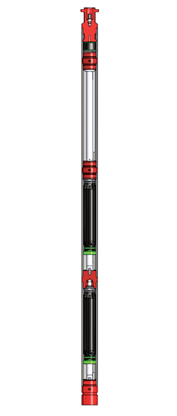
The new patent-pending Defender Super Sand seal section (Fig. 4) is a revolutionary design from Summit ESP that eliminates concerns from sand contamination, upper mechanical seal failure and shaft bushing overload due to incipient buckling of the shaft. The top end of this new seal has “sand exclusion technology” added just above the mechanical seal. This technology prevents sand from falling into the mechanical seal eliminating the initial mode for seal failures.
 |
| Fig. 4. Summit Defender Super Sand seal section. |
|
Additionally, a well fluid thrust bearing has been added to the design, along with an improved head design, which allows for increased well fluid lubrication to cool the bearing.
Relocating the thrust bearing to the top of the seal greatly reduces any concerns of buckling the shaft. The seal includes additional improvements that flush away any accumulated debris from the mechanical seal when the unit is stopped. The bronze shaft bushing has been replaced with a self-aligning carbide bushing set that will operate in contaminated well fluid conditions and offers radial shaft support.
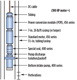
Power cable-deployable ESP system. Zeitecs, Inc. recently announced the initial field installation of the Nautilus power cable deployable ESP system, Fig. 5. The second-generation system requires no tubing-deployed semi-permanent components. Instead, it allows standard ESPs to be deployed on ultra-strong DC coaxial power cable. The equipment includes a downhole power conversion module to convert DC current back to AC to power the standard, 3-phase induction motor. This system is undergoing final field tests.
 |
| Fig. 5. Nautilus power cable deployable ESP system for 51/2-in. tubing/casing. |
|
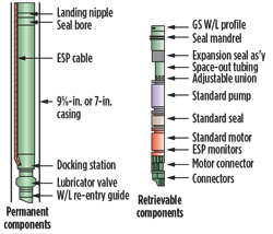
ESP shuttle system. Zeitecs also announced new installations of its “rigless” ESP Shuttle System, Fig. 6. A downhole docking station with a three-phase electrical wet-connector system is first deployed at the bottom end of the production tubing and then the standard ESP system (pump, seal and motor) is run into the tubing on either wireline, coiled tubing or sucker rods. Until recently the system required larger tubing sizes, but it is now commercially available to deploy the complete range of standard ESP sizes from 562 series in 7-in. casing to newly developed designs for 375 series in 41/2-in. tubing. The value proposition of this technology was confirmed recently at an SPE Workshop, where a paper was presented on the first rigless replacement of an ESP on CT in response to an unexpected ESP failure.
 |
| Fig. 6. Zeitecs rigless ESP Shuttle System. |
|
Improved ‘non-invasive’ ESP conveyance system. The Artificial Lift Company (ALC) has released its new V2 Advantage non-invasive ESP conveyance system. This unique technology further simplifies the ability of an operator to quickly and easily install and retrieve ESP systems on slickline, without a rig. The system is designed specifically for high-value wells, where access to the location is difficult, rig interventions are cost-prohibitive and where subsequent delays in production cannot be accepted. It is not unusual in these environments for an operator to lose up to 10% of production to ESP downtime, in addition to the high cost of replacing failed ESPs.
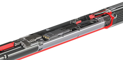
This “rigless” conveyance system combines a robust production-tubing landing string with a side-pocket-mounted downhole wet connector (Fig. 7) and a high-power permanent magnet motor (PMM). The system provides easy installation and retrieval of ESP systems up to 400 hp via standard 0.125-in. slickline (or coil or tractor) through 4.5-in. tubing (or higher hp in larger tubing). It is compatible with 7-in. and larger casing, and can be used with all ESP provider pumps (400 series), VSDs, cables, protectors and gauges. With the ESP retrieved, full bore access is achieved through the well, providing for a multitude of intervention options.
 |
| Fig. 7. V2 Advantage system side-pocket mounted downhole wet connector. |
|
Unlike conventional ESP deployment techniques that require the use of a costly workover rig, the V2 Advantage system provides the ability to install and retrieve ESP systems through a standard 4.5-in. lubricator, without killing the well.
The system has been developed to further increase reliability and address the complicated installation processes used with traditional ESP systems. An important component of the system is ALC’s fourth generation permanent magnet motor. The system’s 3.75-in., 135-hp, single-piece motor is only 9.6 ft long (compared to more than 50 ft for a traditional ESP motor). Motors up to 400 hp are available for this system (3.75-in., 26-ft long). The high power density of these PMMs eliminates the need to run tandem and triple ESP motors to achieve the desired power rating.
Baker Hughes software improves ESP gas-handling capabilities. One of the challenges most operators encounter when producing oil wells is high levels of gas entrained in the production fluid. The presence of gas reduces the pumping efficiency of ESP systems and impacts the bottom line. Gas accumulation prevents fluid progression through the pump, which creates gas locking and causes the system to shut down or potentially become damaged, due to overheating. Gas handling is often a slow, sometimes tedious process with only limited success.
The Baker Hughes Electrospeed Advantage VSD has production software with specific solutions for recurring ESP problems, including gas slugs and gas locking. It features MaxRate software, which is designed to mitigate production interference due to high gas content by automatically purging accumulated gas and controlling the draw down rate to achieve the operator’s target.
Gas is a common challenge for most artificial lift systems. When gas collects in low-pressure areas of an ESP system, fluid progression through the pump stages is blocked, resulting in a gas-lock condition. Due to undulations in horizontally drilled wells, gas tends to migrate to the highest point of a horizontal wellbore creating a gas slug. When an ESP encounters a gas slug, the event can last several minutes or longer. The VSD registers a decrease in motor torque, indicating that the pump has encountered enough gas to stop fluid flow.
The MaxRate software automatically slows the system down to allow produced fluid to backflow through the pump, flushing the gas bubbles from behind the impeller vanes. Once the gas lock is cleared, the drive will ramp the motor frequency back up to resume pumping. The software will make several attempts to break the gas lock condition. If it determines that the situation has not been cleared, a system shutdown will occur to prevent any damage to the equipment string. During the gas purge event, the ESP motor slows down while back-flowing fluid runs past the unloaded motor. This cools the motor and results in extended run life for the ESP system.
The software also contains logic to manage drawdown in challenging situations, such as horizontally completed wells or wells with long-duration gas slugging. By using a novel approach to downhole pressure targets and control loops, operators can automatically manage fluid levels and bottomhole pressure.
Halliburton software targets ESP gas handling performance. Halliburton Artificial Lift continues to refine its unconventional well VSD algorithm technology to work in conjunction with its Q-Max GBP gas bypass technology to improve ESP performance.
The Q-max gas bypass has proven to be effective in increasing drawdown characteristics in very high-GOR wells. The company’s proprietary VSD software works in conjunction with the Q-max gas bypass to consistently allow the ESP to draw the working well pressure farther than previously thought possible.
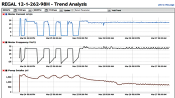
As seen in Fig. 8, this well was shutting down and restarting multiple times in a week. The downtime was costing the operator lost production over a 24-hr period. On March 25, Halliburton’s proprietary VSD program was activated remotely from a computer, hundreds of miles away. The result can be seen from the date of optimization. This well since has run continuously with reduced intake pressures and higher production.
 |
| Fig. 8. Halliburton’s VSD software reduces costly downtime. |
|
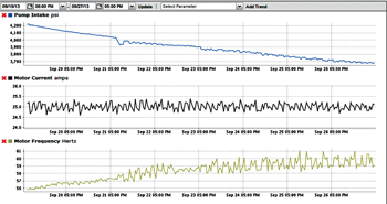
A similar situation is depicted in Fig. 9. After the VSD on the well was programmed to operate using the new VSD algorithm, it stopped cycling and has run continuously. The well continues to slowly draw down the BHP without reducing the stock tank liquid.
 |
| Fig. 9. New VSD software algorithm helps alleviate common gas problems associated with ESP systems. |
|
Since 2010, Halliburton Artificial Lift has installed over 1,800 gas bypass systems in unconventional shale wells. By using proven gas-handling technology coupled with improved VSD algorithms, operators are realizing higher well productivity, a quicker return on investment and a higher degree of reliability from downhole ESP systems.
New software for ESP system optimization. Optimizing artificial lift systems depends on access to accurate and relevant data. While operators and suppliers produce lots of data, some of it may not be relevant to driving artificial lift improvement. Often, if good data do exist, they are so scattered across multiple systems and spreadsheets that they are virtually unusable. Pulling all the critical data together can be problematic.
Artificial Lift Performance Ltd. (ALP) has introduced three new software applications that can be run in the cloud or on a server, all using a core set of relevant data underpinned by application-specific figures to show an operator exactly what a well is doing and what it should be doing. Armed with the difference between the two, action can be taken to maximize well performance at minimal cost.
Well test. Each method of artificial lift differs, but most data-gathering systems primarily tend to focus on collecting production rates. ALP’s Well Test software not only analyzes production data, it also prompts producers which operating parameters to input with the rate information based on the exact form of artificial lift employed, including ESP systems.
Armed with the right data, producers can then base system optimization strategies on results that are specific to their lift system. It’s a more specific approach than standard well test reporting.
Pump checker. According to ALP, this software is specifically designed to optimize ESP production, and diagnose reservoir inflow performance for future ESP system design. The software pinpoints where ESPs are losing production and why. It validates Well Test data (double-checking the input), quantifies lost production and determines bottomhole flowing pressure. It determines whether the lift system is performing as designed.
In Table 3, Pump Checker revealed that this ESP system has degraded by nearly 77% from its performance when installed. That means 180 bpd (or around $18,000/day at $100/bbl) of lost production. With this information, the operator can take appropriate action to maximize well performance.
| Table 3. Pump Checker software calculated that this ESP was under-perfoming. |
|

|
Pump analytics. Using this software, producers can challenge “well conditions” as being the cause of repetitive failures in root cause failure analysis (RCFA) reports from ESP suppliers, by forcing failure categorization through a structured process that drives corrections. The goal is to improve artificial lift performance and ensure fit-for-purpose equipment.
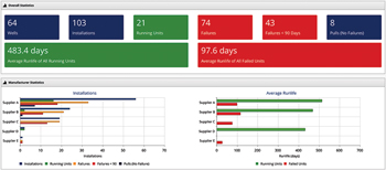
The software helps producers build an easily managed, reliable well and equipment history and failure-tracking database that provides artificial lift system performance for a field over time. With an intuitive “dashboard” (Fig. 10), it facilitates the performance comparison of various systems/equipment.
 |
| Fig. 10. The Pump Analytics user dashboard facilitates the performance comparison of various systems/equipment. |
|
All-in-one ESP control and data acquisition system. Aimed at enhancing productivity and maximizing uptime, Schlumberger has developed a centralized, single platform that provides protection, control and data acquisition for artificially-lifted wells equipped with ESPs.
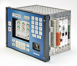
The data-gathering and storage system, the Instruct all-in-one acquisition and control unit (Fig. 11), gathers, analyzes and transmits critical data in real time from surface and downhole sensors to optimize engineering analysis and troubleshooting and manage pump and well performance. The system can monitor up to four wells at once, and transmits data from a variety of sources, eliminating the need for multiple surface components.
 |
| Fig. 11. The Schlumberger Instruct all-in-one protection, control, acquisition and transmission unit with at-a-glance wellsite assessment, and intuitive feedback and control interface. |
|
Users can monitor electrical system data, information from external analog or digital devices, data measured by the downhole monitoring system and remote commands. A modular design provides greater serviceability and expandablitity. The Instruct unit installs directly into the company’s VSDs, and can be configured to automatically make adjustments to optimize well and pump performance, program alarms and trip settings. The unit also has emergency shut-down capability.
For remote monitoring and control, the system can be connected to the Schlumberger 24/7 Artificial Lift Surveillance Center via the LiftWatcher real-time surveillance and optimization service or the SCADA system. The Instruct unit also can operate as a stand-alone device for remote monitoring applications.
Integral to the troubleshooting process, the Instruct unit maintains a record of up to 500 alarms and events in internal memory. By monitoring ESP (or horizontal surface pump) operating data points, it provides protection from fault conditions on any of the monitored signals.
New ESP monitoring system. Schlumberger has developed an ESP monitoring system that ensures continuous communication in case of ground faults, extending ESP run life and reducing failures and operating costs.
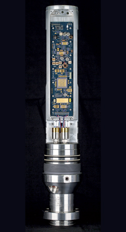
The Endurant ground-fault-immune ESP monitoring system (Fig. 12), represents a significant step-change in addressing one of the biggest causes of failure in ESP monitoring systems, which historically have been highly susceptible to ground faults or electrical shorts. Designed for the high-cost intervention market (including offshore, subsea and harsh environments), the system can continue operating and transmitting measurements even during ground fault cable failure and in high-temperature downhole environments.
 |
| Fig. 12. The new Schlumberger Endurant ground-fault-immune ESP monitoring system. |
|
The system is especially suited for fields prone to ground faults and wells experiencing startup and instability problems, erratic production or needing reservoir build-up analysis. It delivers high reliability in the harshest environments, engineered for high-performance high-temperature downhole monitoring. Designed with metal-to-metal Inconel transducers, a stainless steel body and high-temperature circuitry, the system can operate continuously and reliably in temperatures up to 150°C.
A dual power supply prevents the gauge breakdown caused by ground faults so the system can continue communicating to surface, without interruption. In real time the system receives and transmits intake pressure and temperature, motor winding temperature and pump discharge pressure.
The monitoring system also enhances reservoir understanding by providing an advanced, high-speed telemetry uplink for continuous data transmission at rates of 100 bits per second, even if the ESP is shut down. This facilitates high-resolution, high-sample-rate monitoring of reservoir fluid build-up to determine reservoir performance.
The downhole gauge communicates with a surface acquisition system by way of the ESP power cable. Alarms can be set for individual parameters appropriate to each ESP completion.
PCP DEVELOPMENTS
It was not until the late 1970s that a concerted effort was made to use progessive (or progressing) cavity pumps (PCP) as a method of artificial lift in the petroleum industry. With technical contributions and persistence from many individuals and companies, PCP systems have experienced a gradual emergence as a common form of artificial lift.
Permanent magnet motor PCP top drive. Over the past decade, manufacturers tried developing a direct-drive PCP top drive motor that can perform reliably in demanding applications. Several attempts have achieved moderate success in controlled environments, but none have displayed long-term, field-proven results.
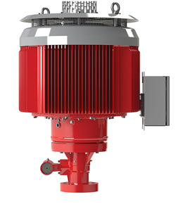
A permanent magnet motor (PMM) PCP top drive (Fig. 13), developed by General Magnetic Group (GMG), is the first commercially successful solution in the market, according to its manufacturer. Due to a partnership between GMG and National Oilwell Varco (NOV) Mono, this product is now part of NOV Mono’s worldwide Artificial Lift Solutions offering.
 |
| Fig. 13. NOV’s permanent magnet motor PCP Top Drive. |
|
Currently available M-75-PMM and M-105-PMM models feature easy installation, reduced electrical consumption and no gearboxes or external moving parts to create potential hazards. These drives help optimize oilfield operations by reducing maintenance, minimizing costly stoppages, and increasing jobsite safety.
Because conventional electric motors only have operating efficiencies over limited operating speeds, even with a VFD, any significant changes in RPMs ultimately require changes in the gear ratio between the motor and pump. PMM driveheads are engineered specifically for PCP applications. Using a permanent magnet motor topology, they are ideal for low- and variable-speed applications.
With a 92.9% system efficiency, these driveheads deliver higher production volumes without increased energy consumption. They also integrate seamlessly with external optimization equipment such as pump-off controllers. With reduced green-house gas emissions and low noise output (68 decibels at 10 ft), they are considered to be environmentally-friendly top drives.
The slightly higher manufacturing cost of creating a permanent magnetic field in the rotor is offset by quantifiable lifecycle savings resulting from lower operating costs, reduced energy consumption and higher system efficiencies brought on by the elimination of speed-reduction equipment.
Because it does not require any electrical current to create a magnetic field in the rotor or losses from speed reduction equipment, the PMM PCP top drive is capable of operating at high efficiencies throughout its entire speed range spectrum.
Changing speed with a PMM drive is as simple as pushing a button on the VFD, which eliminates time-consuming, manpower-intensive well shutdown activities. The PMM can also be integrated with a number of other products, allowing owners to further customize their operations and boost production rates.
The NOV Mono PMM drivehead line delivers full power and torque continuously from 30 to 450 RPM. The driveheads have rated torques up to 1,000 ft-lb and deliver 92.9% efficiency from utility to rod string.
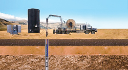
HydraPak PCP. The HydraPak PCP system (Fig. 14) developed by CJS Production Technologies incorporates a coiled tubing umbilical and hydraulically powered submersible motor that connects to a PCP. The submersible motor and pump are conveyed into the well via CJS’s FlatPak or ArmorPak umbilical tubing. Two of the tubes in the umbilical power the submersible motor driving the PCP to force production fluids to the surface. The motor and pump can be reversed to flush solids out of the pump back into the well cellar. The HydraPak PCP system can include a conduit for injecting additives to reduce production fluid viscosity, break down paraffin and other beneficial processes.
 |
| Fig. 14. The HydraPak PCP system includes the CJS triple coiled tubing umbilical, hydraulic submersible motor and PCP. |
|
Using an optional data cable with downhole data sensors, the HydraPak PCP system allows well optimization with information like pump intake pressure, discharge pressure and temperature readings.
The umbilical and PCP system is lowered into the well via a conventional coiled tubing unit. The submersible motor and downhole pump can be positioned in the heel or lateral of the well.
CJS also offers hydraulic surface control automation to monitor and control pump speed and fluid level to prevent well “pump off.”
Flow control technology. To ensure steady and reliable PCP performance, it’s essential to properly regulate the pump speed. Pump too fast and you risk outpacing well inflow, which can lead to pump off and consequential pump failure. Alternatively, if you pump too slowly, you can reduce production to levels far below the well’s potential.
WellPilot flow control technology (FCT) from Weatherford eliminates the guesswork and optimizes PCP performance by constantly comparing pump speed to the monitored flowrate. Used with a variable-speed controller, the WellPilot FCT continuously fine-tunes pump speed to achieve optimal production while protecting against flow loss.
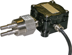
The WellPilot FCT (Fig. 15) has no moving parts. Based on the principle of thermal cooling, the system uses two stainless-steel probes to determine changes in flowrate. One probe generates heat and detects heat absorption, while the other is unheated and acts as a high-precision thermometer. The probes alternate roles periodically, switching between heated and unheated functions, to deter scale and paraffin buildup.
 |
| Fig. 15. Weatherford WellPilot flow control technology. |
|
To determine flowrates, the heated probe detects how much heat is being absorbed by the passing fluid. The higher the flow, the more heat is absorbed, which creates a greater cooling effect. The unheated probe helps fine-tune the flow detection by reading the fluid’s ambient, in-motion temperature. The controller continually analyzes changes in temperature readings from the probes. Based on this information, it signals the variable speed drive, to adjust pump speed in relation to the production capabilities of the well.
The WellPilot FCT is an auto-calibrating instrument. Once installed and powered on, it begins controlling the well immediately. The objective is to always operate the pump at the lowest speed required to deliver maximum production from a well. To find this speed, the instrument follows a patented process called “climb and double-back.” This process assures optimal control and reliability for the PCP. If an increase in pump speed causes flow rate to decline, or if the flowrate remains unchanged as a result of a speed increase, WellPilot FCT automatically compensates. It doubles back, searching through its progressive table of climbing speeds and corresponding flow rates, comparing the current flowrate against those observed at lower speeds. It then starts the climbing process again, selecting the lowest recorded speed that resulted in a flowrate at or above the current production rate of the well. When the control indicates a situation where adequate flow is not being produced, the FCT can be set to shut down the well.
Because gas absorbs heat at a much lower rate than oil or water, the instrument can easily identify gas in the flow line and make automatic adjustments to avoid a pumpoff condition.
When integrated with the WellPilot VSD, the WellPilot FCT delivers a complete set of available safety options to protect the pump in response to well-related problems.
PLUNGER LIFT DEVELOPMENTS
Increasing the range of candidate wells for plunger lift gives operators more options for optimizing well performance and lift economics. Instead of looking at one or maybe two artificial lift methods, operators can analyze costs on multiple methods to see which one may work best, based on the candidate wells.
Plunger design evens fluid production in erratic wells. Multi Products Company focuses on advancing plunger lift technology to increase versatility and fluid handling capability in a wider range of wells.
One of their new technologies recently commercialized is the Steady-Flo plunger (Fig. 16), designed for midrange wells that produce high fluid volumes but lack the reservoir energy to evacuate the fluid. Steady-Flo is a single-piece plunger without any moving parts, and has fall speeds in between common bar stock plungers and high-rate bypass plungers. Because faster fall speeds translate to more plunger cycles per day, and considering that wells must be shut in for conventional plungers to fall to bottom; utilizing this new plunger increases the amount of well uptime, resulting in more production.
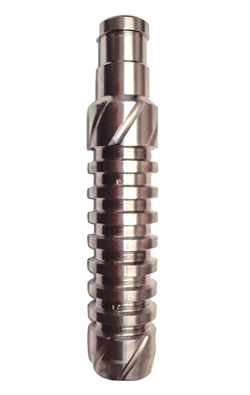 |
| Fig. 16. Multi Products’ new Steady-Flo plunger (12-in. length). |
|
The Steady-Flo plunger incorporates a through-bore design, which allows the plunger to find a hydrostatic equilibrium point in the wellbore by slipping fluid as the plunger rises. With this design, the plunger uses the well’s available energy to produce an even amount of fluid on each plunger cycle, resulting in consistent removal of the fluid load from the wellbore. This helps eliminate the situation of having a well that might bring in a large fluid load on one plunger trip, and then very little fluid on the next trip.
The through-bore design also helps ensure that the plunger falls faster than conventional plungers, which decreases well shut-in time and increases the number of plunger runs per day. It provides more predictable, easily tracked runs, allowing operators to optimize production so that each run delivers a similar fluid volume.
On one highly-deviated 8,000-ft well in the Rockies, an operator was able to increase production 15% by replacing a bar stock plunger with the Steady-Flo plunger. In another near-by well with low reservoir pressure, an operator was required to inject compressed gas to effect fluid production. After installing the Steady-Flo plunger, the operator was able to eliminate compressor use. Fluid production stabilized at 45 bpd and gas production increased by 120% to 220 Mcfd.
Jetted pad plunger. Recently, a major part of Well Master’s effort to increase the effectiveness of plunger lift technology has included the use of computational fluid dynamics (CFD) to evaluate designs and model physical phenomena associated with plunger lift. The use of CFD resulted in a new patents-pending, jetted pad plunger, Fig. 17.
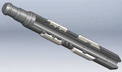 |
| Fig. 17. Jetted pad plunger (note the bore through the center and holes under pads). |
|
CFD’s great advantages are that it can model flow in a CAD model quickly and consistently, and provide an intuitive means of reviewing data as well as quantifying results, which makes side by side comparison of designs a manageable task.
While CFD has a wide variety of applications in plunger lift, Well Master highlights its role in design while considering an issue encountered with padded plungers in horizontal and deviated wells.
At angles above 20° or so, plunger pads collapse, compromising seal and severely limiting performance. A new Well Master plunger design combats this effect by jetting flow from a bore in the plunger to the underside of the pads. This creates an expansion effect, closing the gaps that occur with pad collapse and increasing efficiency. The mechanics of the jetted pad are illustrated using the CFD post-processing, Fig. 18.
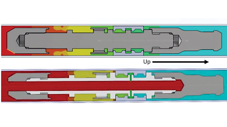 |
| Fig. 18. The pressure cut plot for a regular pad plunger (above) vs. the pressure cut plot for the jetted pad version of the same plunger (below). |
|
In Fig. 19, two cut plots map the pressure for two plunger designs on a plane that bisects through the center of the plunger (warm colors indicate areas of high pressure, cool indicate low pressure). The new jetted pad plunger features a hollow bore with holes that jet fluid from the bore to the underside of the pads. As a principal of fluid dynamics, flow travels from high pressure to low pressure. Here, the high pressure fluid in the bore exerts an outward force on the pad as it leaves the jet before slipping under the upward side of the pad.
 |
| Fig. 19. Flow trajectories isolated to flow that passes through two jets; one in the lower pad set, another in the upper set. |
|
While pressure cut plots are useful for examining how certain features enhance a plunger’s seal, a more intuitive way to observe the flow direction and patterns is by looking at flow trajectories. One of the features of flow trajectories is being able to select an area and see only the flow that interacts with that area: where it came from and where it’s going.
The flow trajectories demonstrate that flow is inducted into the bore of the plunger and forced out of the holes. It shoots through the jet holes against the underside of the pad, mushrooming, and slips out towards the fishing neck. The flow through the jets clearly pushes the pads outward. This closes the gaps created by collapsed pads, increasing efficiency.
OTHER DEVELOPMENTS
Baker Hughes recently opened a $60-million electrical submersible pump research and development facility in Claremore, Okla., Fig. 20. The 80,000-sq ft facility is called the Artificial Lift Research and Technology Center (ALRTC). It is next to the company’s manufacturing center. According to company officials, locating the ALRTC adjacent to artificial lift manufacturing allows engineers from R&D, manufacturing, and the company’s quality and reliability teams to work synergistically to:
- Accelerate new product development and commercialization
- Conduct total system integration testing prior to field installation
- Test alternative intervention methods to mitigate change-out costs
- Meet material traceability requirements.
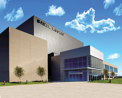 |
| Fig. 20. The new Baker Hughes Artificial Lift Research and Technology Center in Claremore, Okla. |
|
The ALRTC features equipment and system testing options in a wide variety of simulated downhole conditions. At the center’s core are vertical test wells of various diameters and depths to test everything from a single ESP system component to the full production system comprised of artificial lift and other well equipment. 
|


