 |
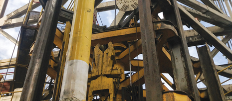
| The 113/4-in. ELHP was deployed successfully after a short design and development cycle. |
|
When a wildcat is drilled in deep water, the challenge is magnified by the distortion and unpredictability of geopressure and temperature gradients produced by the presence of salt diapirs, and stressed pre- and post-salt formation layers. So, when Saudi Aramco drilled its first well in the Red Sea, a rank wildcat deepwater well, it was with the knowledge that the well and casing designs would need to be robust enough to withstand all drilling and production loads, yet be flexible enough to accommodate possible variations. Many of the variations were unknown, because of the nature of the well, and the fact that it was the first in the deepwater Red Sea.
The decision to work with Baker Hughes, to develop and deploy an 11¾-in. version of the TORXS ELHP, was based on the expectation that, to reach the proposed bottomhole depth, the wellpath would need to traverse a massive salt section, subtended by an unknown length of rubble zone. The ELHP was designed to meet and exceed requirements for this application.
PROJECT BACKGROUND
The Red Sea, which separates Saudi Arabia from Africa, is a fault depression that traverses 1,300 mi, from Suez in the north to the Bab el-Mandeb strait in the south, where it connects to the Gulf of Aden, and then to the Arabian Sea. The deepest waters are over 6,000 ft, and the seabed is rugged. Saudi Aramco drilled its first exploration well at a 2,100-ft water depth, approximately 48 mi off the west coast of the Kingdom.
TECHNICAL CHALLENGES
Because the well was a rank wildcat, offset well information was nonexistent, and data from shelf wells drilled in the 1960s were insufficient for informed decision-making on temperature and pressure regimes. Formation tops and pressure predictions were based on a pre-drill analysis, carried out on the basis of 3D seismic surveys. The presence of a massive Mansiyah evaporite salt bed was expected. Seabed geophysical analysis, 3D wide-azimuth seismic, and high-definition bathymetric surveys predicted several scenarios, that indicated a very soft seabed, varying estimates of the top and base of the salt layer, and different pressure trends, depending on the formation sequence below the salt.
The project team was confident about the post-salt formation tops and salt thickness and, as a result, developed a successful well design and drilling strategy to the base of the salt layer. However, the pre-salt environment was less discernible. It is below the salt that the thin margin between pore pressure (PP) and fracture gradient (FG) occurs. The mud density exerts hydrostatic equivalent to the drilling fluid column back to the rig. FG, which results from the overburden of sediments, starts to build, only below the seabed. Because salt has a high FG, it can be drilled with higher mud weight to handle possible creeping or inclusions. This geopressure continuum reverses in the rubble zone. Here, a lower FG is accompanied by high levels of losses. According to the Red Sea geological column series, the Mansiyah salt is subtended by multilayered anhydrite-shale-anhydrite beds. This bedding sequence distorts normal geopressure trends. Correspondingly, PP-FG prediction and mud weight (MW) selection for the exploration well would require astute analytical and predictive geophysical insights ahead of the bit, Fig. 1.
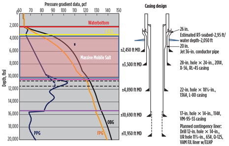 |
| Fig. 1. Pre-drill PP-FG prediction and casing design. |
|
To address the additional challenge of poor imaging and velocity contrast at the base of the salt layer, high-resolution vertical seismic profiling (VSP) surveys were acquired. The high-resolution VSP data were inverted for acoustic impedance; the acoustic impedance profile was converted to interval velocities; and, subsequently, the formation velocity profile was transformed to a PP prediction and minimum MW recommendation.
The predictive utility and workflow of incorporating pressure sampling from a quad combo logging-while-drilling (LWD) tool, and VSP inversion for MW prediction and lithostratigraphic delineation were explored. The combination of VSP inversion and formation pressure tester (FPT) pressure test points was highly instrumental in picking the PP regression. With some precision and operational parameters, MW and projections to the PP-FG trend were adjusted on a timely basis, and as appropriate.
Drilling strategies for this well needed to minimize equivalent circulating density (ECD) and surge pressures, which meant that real-time measurements of hydrostatic pressure and formation pressure would be required for quick decision-making. Depending on formation characteristics and pressures, drilling a slim hole in thin-margin sections of the well could be a contingency option, if any other casing had to be short-landed. However, an important well objective was to reach the planned depth without a slim hole. This objective could be achieved only with contingency liners. The most desirable solution was a liner system, that could be run in tight tolerance, provide required hang-off capacity, create minimum surge, and provide clear indications of setting and disengaging the liner.
EXPANDABLE LINER HANGER AND PACKER
Expandable liner hanger systems in the 7⅝-in. range have been deployed in deepwater wells since the 1990s. The ELHP system for the Saudi Aramco Red Sea well was developed to extend ELHP capabilities to handle hydraulics and large-sized formation evaluation tools, as well as subsea test strings for production test flowrates. Additionally, the thick-walled casing, inherent to sour service-rated tubulars and high production pressures, above and across reservoir sections, required a system that would not be compromised and not be burst- or collapse-limited within structural and geometric constraints.
The deepwater well was planned with five strings of casing below the 18¾-in. high-pressure housing, to which the 18⅝-in. casing was attached. As is the practice in casing design exercises, seismic-derived PP and FG for shale and derived FG for permeable intervals were used to identify casing points.
To reach the proposed bottomhole depth, the wellpath was expected to traverse a normal PP-FG trend to the top of salt (ToS), an unknown length of rubble zone subtending a massive salt section, regression of trend at base of salt (BoS), and—at the time of well planning—three divergent PP pathways that included a total reversal to below hydrostatic trend, if kerogens were present in the deeper formations.
The marked inflection/regression in the PP-FG suggested the need to use a strong 14-in. casing with a 12.213-in. drift to straddle the salt interval and the farthest extent of the rubble zone. The geometric constraint posed by this drift required an uncompromising technical solution. Not knowing what further challenges might exist below the PP-FG regression, the ELHP offered the technical and deployment attributes to exceed the required hang-off capacity and isolation integrity desired. The 11¾-in. ELHP system was planned as a contingency string, primarily to extend isolation of the rubble zone below the salt, should the 14-in. intermediate casing be short-landed. For the unknown length of the rubble zone, the planned 11¾-in. ELHP contingency string could preserve the use of the preferred 9⅝-in. high-collapse casing size across the upper reservoir section. The project team believed that using the next casing size at this depth—9⅝ in.—may have presented through-borehole restrictions, should it become necessary to call for the casing point before reaching or traversing the reservoir sections.
ELHP TECHNICAL DETAILS
The TORXS ELHP system comprises two specific subsystems: the hanger packer and the setting tool, also called the running tool. The hanger packer consists of metal slips and a Baker Hughes ZX-style seal element. The slips provide the hanging capacity, while the ZX element seals the liner top. The hanger packer incorporates a liner top extension, with a polished bore receptacle for stabbing seals of a tieback assembly and also includes a special profile for transmitting torque to the liner string through the drill pipe and setting tool.
Unlike conventional liner systems, both the hanger packer slips and ZX seal are set by expansion forces generated by the setting tool, which consists of an adjustable swage with a hydraulic stroker, an anchor, a flapper assembly, and a cement pack-off. The running tool can be released before cementing the liner, to eliminate the possibility of not being able to release from the hanger after cementing, Fig. 2.
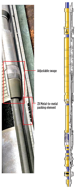 |
| Fig. 2. Close -up view of TORXS setting tool (left) and setting tool schematic. |
|
The ELHP running procedure involves rotating and/or reciprocating the system, while running in hole, if it is required. Once TD has been reached, a ball is dropped and landed on a ball seat within the setting tool. Pressure is applied to the hydraulic stroker by dropping a ball or closing the system, which causes the adjustable swage to travel and expand the hanger body. An overpull test will provide a good indication that the hanger is set, and the running tool is released. Pressure is then increased to extrude the ball through the ball seat within the setting tool to reestablish circulation, release the anchor, and reset the stroker. Cementing operations can now be completed.
After the cementing, the flapper is closed within the setting tool, just with pipe movement, and pressure is again applied to the stroker. This second expansion stroke is performed to further expand the hanger body to set the ZX seal. Pressure is then elevated to burst a rupture disc within the flapper to reestablish circulation. The packer seal should be tested at this point, and the setting tool then retrieved.
Development of the 11¾-in. ELHP necessitated full concept-to-prototype engineering development and up-scaling of several previous ELHP components for deepwater application. An extensive design qualification process during the short concept-to-prototype cycle included finite element analysis and modeling, and exhaustive tests on components and assemblies that made up the integral hanger/packer and tieback extension system and the setting tool. Full function tests also were performed for the entire hanger packer setting sequence, followed by a pressure test of the packer at full collapse and burst pressures. The resulting system combines wellbore isolation and deployment performance most suitable for preserving through-bore casing size, without compromising pipe strength, hanger capacity, or leak-path seal integrity.
The simplicity of the new ELHP downhole components enhances reliability by reducing susceptibility to additional leak paths that are inherent with conventional liner equipment. Because the running tool applies the setting force hydraulically and is load-neutral during run-in-hole (RIH), the system can be set in highly deviated and horizontal wells, and subjected to high circulation pressures, with no risk of prematurely activating the setting mechanism. Additional advantages include less limitation to the setting force applied to the hanging slips, rapid confirmation that the hanger is set and the liner is in place, and greater wall cross-sectional contact, giving the system the potential for higher pressure and hanging capacity.
WELL CONSTRUCTION
The homogeneity of the salt section, consistency, and low temperature (262°F VSP temp.) created benign conditions for drilling across the salt. Approximately 5,800 ft of salt—mostly halite—was drilled with a 17-in. hole. At 900 ft, from the predicted BoS, a walkaway VSP survey was carried out to provide a look-ahead for formation and pressure transitions.
Rubble zones, rugose transition planes, seams, welds, and protracted occurrences of anhydrite/shale/sand sequences were anticipated at BoS, as is expected in most subsalt exploration wells. After analysis of the VSP and quad-combo log data, a precise location for isolating the salt rubble zone was identified.
A string of 14-in. casing was set at 10,689 ft, at a casing point below where a second streak of anhydrites was confirmed. With the salt behind casing, the next set of challenges was to determine where the PP transgression and regression inflexion point occurred, make correct MW adjustments, and refine predrill PP-FG predictions. The drilling engineering and exploration teams decided to use as many formation-while-drilling measurements as possible, to carefully navigate the PP ramp and reversal, while managing drilling parameters and MW on the fly.
In preparation to ride the ramp, MW was adjusted from 113 pounds per cubic ft (pcf) to 118 pcf. As drilling progressed from the bottom of the 14-in. casing, circulation losses occurred, despite several analytical models indicating an 18-pcf window between PP and FG. Lost circulation material (LCM) was pumped and, with some soak time, hole circulation was regained, momentarily. Because only 200 ft of new hole had been drilled below the 14-in. casing shoe, the option to run a liner to isolate losses was not acceptable. Additionally, it was important to know the vertical extent of this loss zone.
The drilling BHA was modified, and drilling continued with less-sensitive LWD components, and a bit with bigger jets for spotting LCM. Difficulty troubleshooting the losses was three-fold: 1) a lack of returns to surface precluded physical description of the formation using cuttings; 2) drilling ahead with losses prevented placing LWD sensors to get petrophysical data; and 3) pressure-while-drilling (PWD) data were erratic without a stable annular fluid column.
Mud weight was reduced from 118 pcf to 115 pcf, and then to 110 pcf, to enable pumping at a higher flowrate. Dynamic losses subsided at various modeled and indicative fracture closure ECDs, and at optimal flowrates. With a new equilibrium established between drilling parameters and formation mechanical and hydraulic capacity, drilling progressed to section TD and a total, drilled interval length of 1,345 ft. The hole was then underreamed from 12 in. to 14 in., to minimize surge effects with ample annular clearance for the 11¾-in. liner and to help increase trip speed. As MW was adjusted to achieve the overbalance to hold the gas back, the kick tolerance of the hole section diminished precariously, especially relative to the 18⅝-in. casing shoe strength, Fig. 3.
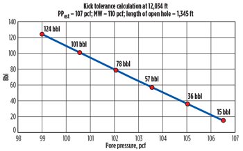 |
| Fig. 3. Kick tolerance plot, showing diminishing tolerance margin with increasing PP. |
|
Given the preceding well construction progression, the decision to run the liner was underscored by the desire to: 1) improve the kick tolerance in the hole section; 2) isolate the lower-pressured shale formation just below the previous shoe; and 3) increase mud weight to maintain well control in the progressively higher-pressured zone at the bottom of the interval. As drilling progressed beyond the depth of PP regression, the well encountered a progressively higher-pressured sandstone zone, as indicated by increasing background gas (average 10 to 70 units).
ELHP DEPLOYMENT
Job design and planning for the first deployment of the evolutionary ELHP technology required a meticulous assessment of well status, load envelopes and paths, operational hazards, and application exigencies.
A Baker Hughes development engineer inspected the ELHP in the shop, and noted the larger cross-sectional area across one of the setting tool assemblies, which necessitated a cautionary run-in-hole note to be added to the ELHP job program.
At the wellsite, after rigging up the top drive head, the shoe track was run in hole and the 11¾-in. joints were then run in at a rate of 5 min. per joint. After the ELHP assembly had been made up to the liner string, a weight check was conducted, and a pick-up of 320,000 lb and slack-off of 340,000 lb (including 240,000 lb for the top drive) were recorded. The hanger/packer assembly was visually inspected for any damage, and was assessed to be in excellent condition. The liner hanger assembly was then lowered through the rotary, and the drill pipe (DP) slips were set on the lift nubbin. To prevent collapse or damage, care was taken not to set slips on the liner hanger/packer tieback extension.
As the liner assembly progressed downhole, mud began flowing from the drill pipe because of liner filling and the reduced internal diameter of the DP, compared to that of the liner. Trip speed was reduced from 5 to 25 min. per stand, to manage surge and piston effects of the 11¾-in. liner in the 12.213-in. drift of the 14-in. casing. With the liner string at the 14-in. casing shoe, one liner volume of mud was circulated at 400 gpm.
After a second weight check, 510,000 lb of pick-up weight and 500,000 lb of slack-off weight were recorded. It was decided not to rotate the liner string, and tripping proceeded into the 14-in. underreamed open hole.
Three stands before reaching TD, a 1¾-in. ball was dropped and chased with 2-bpm mud, to help it reach the float collar and convert from autofill to conventional. A final weight check recorded pick-up of 530,000 lb and slack-off of 520,000 lb. The space-out of the liner string was carried out with depths tide-corrected to ensure location of the liner shoe at the required depth of 11,950 ft. The packer element was placed, as close as possible, in the middle of a casing joint.
Pumps were activated to clear flow bypass areas and move fluid around the liner. While circulating, returns were monitored continuously to ensure that bridging in the annulus would be detected promptly, should it occur. Cementing lines were aligned and flushed, while circulating to, further condition the hole and the mud. With circulation completed, the 11¾-in. liner guide shoe was placed at 11,950 ft, and the 2⅛-in. OD hanger setting ball was released.
Approximately 34 min. after being launched, a slight pressure indication on surface confirmed that the setting ball had landed on the ball seat. Pressure was gradually applied to 3,500 psi, then to 4,300 psi, and finally to 4,750 psi. The running tool was released automatically from the liner, and the hanger was set.
After cementing, the stroker was lowered into reset position, and the anchor was set. Pressure was brought up to 3,500 psi. Collet release was observed at 2,800 psi, and stroke action began downhole, with pressure rising to 4,800 psi, to indicate that the packer expansion process was complete. Setting pressure was held at the running tool for 30 sec, to allow the tool to complete the second full stroke, Fig. 4.
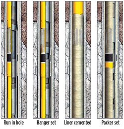 |
| Fig. 4. TORXS expandable liner hanger packer deployment process. |
|
PROJECT SUCCESS
Following a very short design and development cycle, the 11¾-in. ELHP was deployed flawlessly in its first field application. 
ACKNOWLEDGMENT
This article is adapted from SPE/IADC paper 166803, “World’s first successful deployment of an advanced 11¾-in. expandable liner hanger in a deepwater exploration well,” presented at the SPE-IADC Middle East Drilling Technology Conference and Exhibition, Dubai, UAE, Oct. 7-9, 2013.
REFERENCES
- Al-Husseini, M.I. 2008, “Middle East geological timescale,” GeoArabia, Journal of Middle East Petroleum Geosciences, 2008, Vol. 13, No. 4, Gulf Petrolink, Bahrain.
|


