 |
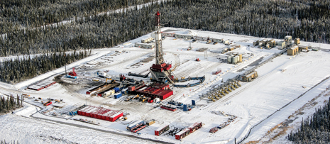
| Aerial view of the c-1-J well pad at Dilly Creek in northeastern British Columbia. Average total length was 5,100 m, including the Horn River well which, at 5,633 m, set the record as the longest Horn River well in Nexen’s history. |
|
Drilling productivity has improved multifold in the Horn River basin, since activity began about four years ago. In its early days, a typical well took about 40 days to drill from spud to cementing the production casing. A range of improvements has been implemented, reducing drilling time three-fold, despite the increasing complexity of the wells.
Examples of these improvements include a pad rig moving system, bigger drill pipe, rotary-steerable and managed-pressure drilling, and high-temperature motor elastomers, along with project management practices of performance monitoring and improvement, by comparison with yardsticks established to challenge the status quo.
One such measure of performance is ROP achieved from spud to rig release. Some of the recent wells, which were drilled to about 5,000 m, were accomplished at 438 m/day, which is a record in the Horn River basin. The same performance was repeated on the next two wells. In comparison to the early wells, the recent performance offers a cost reduction of $40 million over the course of a 20-well pad.
HORN RIVER BASIN
Located in the northeasten part of British Columbia, Horn River basin is the third largest resource play in North America. The shale package, at about 2,500 m, TVD, is up to 320 m thick in the Fort Nelson area. The targets are three gas-bearing formations—Muskwa, OtterPark and Evie—which are tight shales requiring fracturing to release the gas. The field development plan calls for multiple, parallel horizontal wells, drilled at 300–400 m spacing, determined by the fracture propagation lengths in each formation, Fig. 1. The horizontal portion is then fractured at regular intervals. A number of horizontal wells are grouped and drilled from one surface location to minimize the environment impact. These surface locations are called pads, which are typically built for 20 wells, in two rows of 10 wells, each.
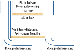 |
| Fig. 1. Initial well design with intermediate casing (left) and current well design (right). |
|
TECHNOLOGY IMPROVEMENTS
Walking rig reduces flat time. The first wells were drilled with a conventional rig. Drilling multiple wells from the same pad brought rig move time onto the critical path and resulted in rig upgrades for moving systems, Fig. 2. Four hydraulic jacks essentially lift up the entire substructure and mast with full complement of tubular. The jacks have the ability to stroke in any direction, up to 1 m at a time. Wellheads are spaced 5 m apart. Consequently, a typical move between two wells was reduced to 2–3 hr.
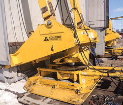 |
| Fig. 2. The rig is lifted on four of the Columbia lifting system pads, one installed per corner of the rig floor. |
|
The next step was to avoid positioning all the rig equipment to facilitate the move. This was accomplished by designing an umbilical system based on moving suitcases, Fig. 3. Each suitcase comprises mud lines, well control fluid lines, and all electrical lines connecting the centrally located rig complex to the drill floor. The number of suitcases required is determined by the distance between the central rig compound and the farthest well on the pad. This farthest well is normally chosen to be the first one to drill, so that the suitcases and lines can be tested in their most extended configuration.
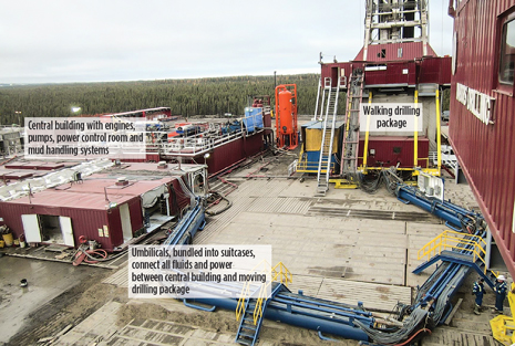 |
| Fig. 3. Umbilicals connect the central complex to the moving rig package. |
|
On the last four pads, the flat time from bumping the plug to drilling out the shoe track on the subsequent well was less than 24 hr. This included laying down the landing string; moving the rig to the next well; nipple and pressure test the BOP and choke manifold; run in the hole and drill out the surface casing shoe track. BOP nipple-up time was reduced through a speed-loc type of connection between the top wellhead flange and bottom BOP flange. This connection could be taken apart in a matter of minutes, as opposed to a conventional flanged connection.
Slim well design. Early wells utilized a conventional, 3-string casing design with surface, intermediate and production casing strings. The surface casing was used to cover the ground water and would be set above the loss-bearing zone. The intermediate casing was set just inside the Muskwa target formation. Then, the production casing was designed for fracing and set at the well’s TD. Earlier well design and the slimmed down version are shown in Fig. 1. It was possible to eliminate the intermediate casing, when it was established that the increase in mud weight does not help to keep gas in the formation pores. The surface casing was pushed into the Shunda formation, just below the loss zone in the Debolt formation, as the initial wells showed no evidence of hydrocarbon-bearing zones above. The formation strength of 18–21 KPa/m in the Shunda proved to be sufficient for drilling to the well’s TD at ~2,600 m, TVD, with mud weights in the 1,300-to-1,400 kg/m3 range.
The gas contained within the fractures, which was liberated by the drilling process, was circulated out of the system, using a rotating head and a high-capacity separator (65 Mcfd). This allowed drilling with reduced weight while flaring the gas. This process led to carrying two separate drilling fluid systems: drilling weight and kill weight fluids. Drilling weight was typically kept around 1,030–1,080 kg/m3, and kill weight ranged from 1,300 to 1,380 kg/m3. Drilling fluid was used to drill the interval. Prior to tripping, the drilling fluid was displaced to kill fluid, to maintain conventional barriers.
Mitigating drilling risks. Pushing the surface casing below the Debolt formation posed some challenges with cementing above the loss zone. Zonal isolation was required below the loss zone, to allow for drilling to TD and above the loss zone, to protect the groundwater. External casing packers (ECPs) and stage tools were utilized in a two-stage cementing technique. The first stage established isolation below the loss zone, and the second stage was pumped after setting two tandem ECPs above the loss zone through a stage tool.
The reliability of stage tools should be looked at closely. A few lessons were learned in utilizing the balance inventory from a two-year-old project. Even after passing function and pressure testing in the lab, the tools did not hold pressure upon closing in the field and resulted in extra wait-on-cement time in some cases. The placement of ECPs in the wellbore also requires attention. Setting the ECP in a washed-out zone reduces its sealing ability, and in some cases, called for a top-up job from surface.
Lower drilling weight had the potential for instability in the shallower formation overlaying the reservoir zone, namely the Fort Simpson shale. The instability was realized on two occasions, leading to stuck pipe and sidetracks. Further study linked this phenomenon to inclinations exceeding 40° at 30° to 60°, and 210° to 240° azimuth ranges. Subsequent wells were planned to avoid these angles in the Fort Simpson formation.
Maximizing exploited reservoir with negative section. The first-generation wells were drilled vertically down to kick-off point (KOP), and thereafter, a straight build to land in the target formation. The trajectory consumed a vertical section of about 450 m between the surface location and the heel of the lateral section. With pads, the need for drilling the farther, outside lateral sections required some changes to the trajectory. There were two available options:
- Drill straight to a shallower KOP, and then build and turn to land. This approach resulted in deeper KOPs, which was perceived as a benefit from a performance perspective, since it was possible to drill to KOP with minimal sliding. This was the first one to be adopted.
- The second approach was to kick off at a shallower depth and hold a low-angle tangent, to gain the separation required to land at the heel of the lateral section. The tangent section required more sliding and was seen as less favorable. Later, this approach was adopted as a standard, especially as well designs evolved to minimize the unused vertical section.
Figure 4 illustrates a plan view of both approaches implemented on the c-1-J pad. The nine wells drilled in 2010 implemented the first approach and had their heels at about 450 m of vertical section from the surface location. The 2013 wells were planned, using a fish hook design, whereby the heels were at a negative section behind the surface location, on nine out of the 10 new wells, to exploit the full extent of reservoir. The middle well could not be planned with a negative section, due to concerns with proximity of previous wells, which were all on production.
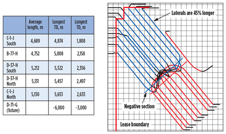 |
| Fig. 4. Wells drilled in 2009 without a negative section (red). Wells drilled in 2013 (blue) were designed with a negative section to exploit the reservoir left underneath the pad’s surface location. The table on the left shows the well design progression, with increasing lateral section lengths, pad over pad. |
|
A newer approach to pad planning is shown in Fig. 5, which shows the plan view of the d-37-H pad. The key difference, here, is that the south row of wells was used to drill the north laterals, and the north row of surface locations was used to drill the south laterals. The approach reduces the extent of the negative section, while maximizing the exploited reservoir underneath the surface location.
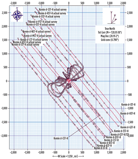 |
| Fig. 5. Plan view of d-37-H pad design, with negative sections and criss-cross pattern. The north side surface locations were used to drill south side laterals, and vice versa. This approach was found to reduce the extent of negative section without compromising the reservoir recovery. |
|
From an operational standpoint, pad drilling poses the challenge of close proximity when drilling surface holes, since the wellheads are only spaced 5 m apart. All the surface holes were drilled as a batch, which meant that the risk of collision with another surface hole was financial only, since none of the close wells had penetrated the reservoir section. The risk was minimized further by managing the drilling sequence and nudging strategy. The nudges were planned, such that by the end of the surface-hole phase, all wells were at least 20 m apart, Fig. 8.
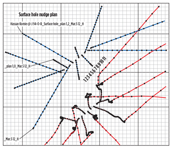 |
| Fig. 8. A surface nudge sequence is illustrated, whereby adjacent wells are nudged in the opposite direction. The first five wells are drilled by skipping over the adjacent slot to maintain a good MWD signal. The missed slots are then nudged, using a scribe line at very shallow depths to minimize steel interference. |
|
Surface holes for wells 1, 3, 5, 7 and 9 were drilled, using conventional MWD, since they were 10 m apart. Surface holes for wells 2, 4, 6, 8 and 10 were drilled, using a scribe line to orient the toolface for the first 200 m, until it was possible to get a clean MWD signal. The technique was cost-effective in managing the risk and was used on all pads. All surface holes were designed to nudge at 75 m, which is 40 m below the surface conductors, and all wells are planned to nudge away in opposite directions.
The main holes were planned with three different dogleg severities. Low doglegs of 2° to 2.5°/30 m were used to get to the tangent angle of 15°–35°, depending on the position of the well on the pad. The final approach to heel utilized 3.5°/30 m in the Fort Simpson formation, and 5°/30 m below the Fort Simpson into the target zone. The Fort Simpson has, historically, proven unpredictable for dogleg response. Initial wells planned with 5°/30 m saw multiple trips in the Fort Simpson, to adjust the motor bend settings. It is an added benefit of the fishhook design that it allows for low angles through the Fort Simpson, without compromising the vertical section.
Drill string selection. The initial wells were drilled with a 4-in. drillstring, which was replaced with 5-in. pipe on the next pad. The main drivers were better toolface control and hydraulics. The c-1-J pad, and a few wells at the start of the b-77-H pad, were drilled using 5-in. E75 and X95 pipe with NC 50 connections. Although the pipe had adequate tensile strength, the torsional limits of the tool joints were reached, especially on the outside wells, while drilling the lateral section. This would lead to drilling with reduced parameters, such as rpm and WOB. Figure 6 shows the operating parameter, in relation to torque limits of different tool joints.
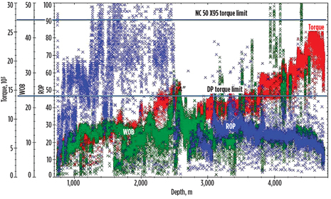 |
| Fig. 6. Drillpipe torque limitations superimposed on the operating torque demonstrate the benefits of utilizing higher torque pipe and connections. |
|
The entire string was replaced with 5-in. string that has a high-torque connection string with two different weight ranges—the conventional 19.5-lb/ft version and the heavier 25.6-lb/ft pipe. The connection torsional limit was high enough for drilling operations. However, the lengths of the wells and their high flowrates required hole cleaning with high ROP, despite the inner diameter restriction of the heavier pipe. A valuable hole cleaning lesson was learned on one of the wells, where insufficient rpm and flow to maintain ROPs in excess of
60 m/hr in the lateral section led to pack-off, stuck pipe and a sidetrack.
A range of practices was implemented to achieve adequate hole cleaning. One of the measures was to alleviate the flow restriction by upgrading the string to a 5.5-in., high-torque connection. The connection was selected, such that its OD matched the NC50 connection, and, therefore, did not reduce the rig’s pipe racking capability. The string of choice for the project, which meets the hydraulic, torque and drag requirements of these wells, is a combination of 5.5-in., 21-lb/ft and 24.7-lb/ft S135 pipe with high torque connection, allowing about 35,000 ft-lb of operating torque.
Directional technologies. To maximize ROP in the first section, which extends from drillout of surface casing to the heel, the extended power section motors were replaced by even-walled motors, due to their superior torque characteristics and better steerability. Longer power section motors (also called greater torque motors), with hard rubber and 7-in. bearing sections, have also been used and are able to provide the same level of torque and steerability performance as even-walled motors. The 7-in. bearing sections has shown better steerability, in comparison with 6¾-in. bearing sections.
The combination of high temperatures and oil-based mud in the reservoir section had the predictable effect on motor elastomers. There was a rash of chunking-related motor failures. These failures were traced back to elastomer swelling and the need to manage the rotor stator fit. Motor life was extended through single oversize (slightly oversize stator, but conventional rotor) and double oversize (undersize rotor in an oversize stator). However, there was a price to be paid in performance. Motor torque capability reduces with oversize, and is further derated by elastomer swelling. The motors were typically operated at about 40% of capability in a conventional, low-temperature environment.
Hole cleaning practices. This discussion concerns the OtterPark B formation, which is rich in clay and organic content, and usually delivers superior ROPs. With faster ROPs, however, hole cleaning becomes a bigger issue. Two consecutive Otter Park B wells required several wiper trips and instances of back reaming. A stuck-pipe incident eventually occurred while drilling a third well. Learning from the incident root cause analysis, the following measures were adopted:
- The build section BHA with 1.83° bent housing is allowed to drill a maximum distance of 200 m after the well is landed. A trip is mandated to change the BHA at this point. The 200-m interval in the lateral is usually a section, where string is rotated from surface for 80% to 90% of the time. This allows cleaning of hole from cuttings potentially accumulated during the build section, where sliding is predominant.
- A rotary steerable BHA is preferred to drill the lateral section, using 160–180 surface rpm. This is backed up by a conventional lateral section BHA with 1.5° bent housing, which also can be rotated at 100 rpm.
- Prior to any trip out of the hole after landing, the well must be circulated for a minimum two full bottoms-up, followed by displacement to kill mud and another two full bottoms-up with heavier kill mud. Maximum rotary speed and pump rate are to be maintained while circulating. Studies were performed to understand the amount of circulation required to clean the hole, which indicated 8–9 bottoms-up. In practice, it was established that 4–5 bottoms-up would accomplish the same result.
- Maintain the 6-rpm and 3-rpm Fann readings of the drilling mud between 8 and 10 throughout the lateral section.
- A downhole drag model utilizing different friction factors must be established, to monitor trends in drag as early warning signs for poor hole cleaning. Once in the lateral section, the drillstring is worked full-stand after five stands of drilling. These up-and-down hookloads are recorded by the driller and compared by the engineer with the model data.
The measures have been largely successful. To date, five more OtterPark wells have been drilled, without any issues, after adopting the new practices. Three of them set new industry records in the Horn River basin, achieving 431m/day, 438 m/day and 442 m/day, from spud to rig release, due largely to the superior ROPs in the lateral section.
CASE FOR ROTARY STEERABLE SYSTEM
Drilling the lateral section with motors has become increasingly inefficient, due to the need to stay in specific formations in longer laterals. The ROP performance with motors also left a lot to be desired, due to differential pressure derating of the elastomers and clearance fit between rotor and stator. This opened the door for experimenting with the rotary steerable system (RSS), whereby it was possible to maintain directional control in the lateral section without using a downhole motor. An additional benefit was better hole cleaning, a key focus after the aforementioned stuck pipe event.
The learning curve while implementing the RSS was fairly long and required some perseverance by the drilling team. The first RSS run saw correct responses from the tool. However, it exposed surface problems with the top drive system (TDS). The control loop was unshielded from power chords, which introduced high-frequency noise when operating the TDS at higher rpm. The noise simulated braking action, resulting in abnormally high torque at the TDS. On that particular well, a separate torque sub was used on an experimental basis below the TDS quill. This was very helpful in relating the source of erratic torque to the surface equipment. After shielding the surface control loop, the problem went away.
One of the difficulties with drilling the build with motors, and then running RSS for the laterals in the same hole size, is the ability to run past the build section. The best-build BHA for these formations is a slick BHA, whereby there is no stabilization on, or above, the motor. It results in somewhat higher tortuosity, but it is preferred, due to interbedded formation sequence, which results in hanging up when using stabilizers. The higher tortuosity, however, posed problems when the same-gauge, stabilized BHA is run through this hole, requiring excessive reaming. The solution to this problem was downsizing the lateral section. The combination that worked utilized a 222-mm hole with slick motor BHA, followed by a 216-mm, fully stabilized RSS BHA to drill the lateral section.
The following benefits were seen from utilizing RSS in the lateral section:
- Consistent on-bottom ROP. Without a downhole motor, there was no motor differential to manage, and therefore, it was possible to maintain consistent WOB and ROP.
- Long bit life. Consistent WOB meant that the bit was not exposed to erratic weight transfer while sliding.
- Less tortuosity. The entire lateral was drilled in rotation, eliminating any micro doglegs from slides.
- Improved hole cleaning. Continuous, high, 160–180 rpm, combined with a high flowrate, allowed better removal of cutting beds from the lateral section.
- Fast casing run. Typical wells drilled with motors left a bed of cuttings in the hole, due to a restriction on rpm imposed by the motor bent housing. Casing runs were longer in wells drilled with motors, as the hookload would deplete down to traveling assembly weight, partway in the lateral, requiring the casing to be worked to bottom. A cleaner lateral section with RSS allows casing all the way to the planned TD, with sufficient hookload to allow for setting the wellhead mandrels, Fig. 7.
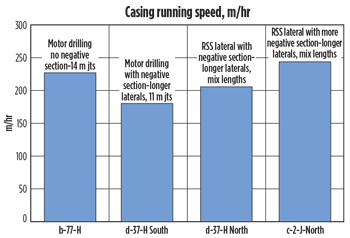 |
| Fig. 7. Casing running speeds plotted for wells drilled with motors, as well as RSS. The wellbore drilled with RSS is generally cleaner, due to higher rpm, and casing can be run to bottom, without the need to slingshot or push with sufficient weight available to land the casing hanger and set the seals. |
|
PERFORMANCE BENCHMARKING
The implementation of new technologies is driven by a rigorous performance monitoring and benchmarking process. Benchmarking of performance data is structured to rank well-to-well performance and set targets to build on the results. Each well is divided into various intervals for tracking depth, duration, and non-productive time (NPT). These data are used in developing AFE time and cost estimates for upcoming pads. The results from all wells on the previous pad are used to determine the average and fastest times for each of the categories described earlier. The shortest durations are added to get the P10, and the average times are used for calculating the P50 estimates.
AFE generation requires a precise estimate for the total number of days needed for drilling the wells being planned. Each well has a unique profile, which results in varying landing points and total depths. In this case, ROP information from similar wells is used to calculate the estimated time for drilling vertical and horizontal sections. The P50 averages for ROP in the build and lateral sections are applied to the actual lengths of each well, to get an accurate time estimate. Aggregated performance KPIs are used for flat times and drilling to the landing point.
However, drilling rates in the target zones, namely Muskwa, OtterPark and Evie, vary. Being a harder formation, Evie generally requires additional bit trips and results in lower ROP. It is, therefore, more realistic to segregate the lateral section KPIs for each formation. A score card is made for every well, utilizing the AFE estimate for each well. The actual performance is compared with the planned performance to identify the high and low lights, which then very often become lessons learned for future wells.
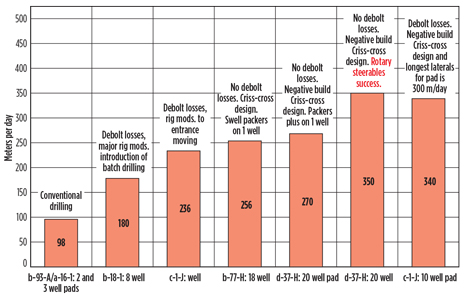 |
| Fig. 9. The m/day performance is compared to the previous pads drilled in the Horn River basin, to show the impact of each new technology implementation. |
|
A metric used for comparing overall pad and well-to-well performance is the m/per day average. It is calculated by taking the ratio of total meters drilled and the duration from spud to rig release. The m/day measure encompasses all activities carried out in the drilling process and includes all NPT events. This is a normalized metric, which can be used to compare any two wells or pads, even if they are drilled in different formations or to varying final TDs. When planning for the next pad, 5% improvement is targeted, compared to the previous, overall meters per day. Figure 9 shows the improvement in m/day achieved through the implementation of new technologies over the various pads drilled in the last four years. 
ACKNOWLEDGMENT
This article is adapted from SPE paper 167725, presented at the SPE/EAGE European Unconventional Conference and Exhibition, Vienna, Austria, Feb. 25–27, 2014.
|


