JAMES F. LEA, PL Tech LLC; HERALD W. WINKLER, Texas Tech University; JOE D. WOODS, International Pinpoint; and MARK S. GARRETT, Marathon Oil
Allow us a moment to say “thank you.” For decades, Jim Lea and Herald Winkler have penned this annual trademarked series on artificial lift. For decades, production engineers have followed the words from these pages into the oil fields of the world. Hundreds, if not thousands, of oil field workers have applied what they discovered in the writings and teachings of Lea and Winkler to well after well. The net effect has been improved well performance and reduced artificial lift costs for many production companies.
Lea and Winkler will soon pass their pens to a new team of contributors, who vow to continue this iconic series. Hence, with this year’s publication, we welcome Joe Woods and Mark Garrett to the team. We also take this opportunity to give a nod of the proverbial pump jack to Jim Lea and Herald Winkler for over 25 years of exemplary service to these pages and, moreover, to the industry at large. Well done, gentlemen. Thank you.
Turning the page. According to a recent study by MarketsandMarkets of Dallas, the global artificial lift market, in terms of revenue, was estimated to be $9.3 billion in 2012 and is expected to reach $16 billion by 2018. Other analysts have estimated the market to be even higher. Sources indicate that Spears & Associates peg it at almost $13 billion in 2013. North America dominates the artificial lift market, accounting for an over-45% revenue share.
Whatever the exact dollar value may be, artificial lift—more than ever—is recognized as a large, growing and technically important segment of the energy industry. For these reasons, perhaps it would be appropriate to pause and review the various forms of artificial lift and to underscore the importance of selecting the proper lift system, while still asking the important question, “What’s new in artificial lift?”
New is a relative term. Often in our industry, as in our society, things that are old become new again. Maybe a good industry example is hydraulic fracturing. Recently, news media reporters from New York to New Mexico have had their audiences believing that “fracing” (or is it “fracking”?) is some newly discovered technology gone awry.
While fluid and proppant systems, equipment horsepower, zone isolation equipment and application trends may change, fracturing techniques have been applied to wells since the 1940s. Following a burst of activity in the mid-1950s and an upsurge in the mid-1980s, hydraulic fracturing became a routine well completion method. Today, fracturing is arguably the most widely used stimulation/well completion method in the world. It has been a crucial factor in improving the recovery of hydrocarbons from many reservoirs for many years.
Similarly, most artificial lift systems would not be considered “new” technology by today’s industry professionals. In recent years, the emphasis has been on lowering the operational costs of production systems and optimizing well performance. This has required focused application engineering, proper system selection, the development of more efficient installation or deployment techniques, and improved operational efficiencies of existing technologies. Moreover, there has been a growing emphasis on the timely monitoring, communicating, and analyzing of well performance and production data.
ARTIFICIAL LIFT OVERVIEW
Many regions and countries have inadequate or inaccessible industry data recording and reporting systems. Hence, estimating the number of producing wells in the world is problematic. By most guesstimates there are well over a million globally. Of those, maybe 5% flow naturally. The remaining 95% of producing wells rely on some form of artificial lift, at some point in their production life cycles.
Artificial lift is required on oil wells, when there is insufficient pressure in the reservoir to propel or lift the produced fluids to the surface. Also, artificial lift systems are frequently used in the dewatering of gas wells.
Artificial lift technologies are wide and varied. The term, artificial lift, applies to numerous tools, equipment, controls, instruments, computer hardware and software, technologies and techniques used to increase the flow of liquids (usually crude oil, water or a mix of oil and water along with natural gas) from a production well. The lift can be achieved mechanically with a pump. It can be as simple as altering the well’s flow regime by installing a velocity string. Alternatively, lift can be achieved by decreasing the hydrostatic column weight in the well by injecting gas into the liquid at the desired depth.
There are three categories of artificial lift systems: 1) pump-assisted systems; 2) fluid-assisted systems; and 3) flow enhancement techniques. Within these three categories, there are eleven types of lift technologies. In each category, there also exist unconventional or emerging technology types of lift. Table 1 identifies the three main categories and the corresponding methods of artificial lift within each category.
| Table 1. Categories and types of artificial lift systems |
|

|
Too often, the method used to select an artificial lift system is a “we’ve always done it this way” decision process, rather than a strategic plan based on well optimization.
System selection. Proper selection of an artificial lift system should include an analysis of the individual well’s parameters and the operational characteristics of the available lift systems. Analysis should start when reservoir, drilling and completion decisions are being made; not after the well has been drilled and completed.
Different pumps and lift systems have unique operational/engineering criteria, but they all require similar data to properly determine application feasibility:
Dimension limitations. The first question is, “Can the lift equipment physically fit into the production casing, liners and/or open hole?”
Wellbore configuration. The general shape of the wellbore can, in itself, eliminate or reduce the effectiveness of various lift types. For example, a horizontal well presents more challenges related to gas inference than a vertical well. Additionally, dogleg severity can be high enough to eliminate some lift options.
Desired rate vs. depth. Some lift types have rate limitations while others have depth limitations. For all forms of lift, the achievable rate decreases as the depth increases. This is due to power requirements, equipment overload, pressure limitations, temperature limitations and/or total dynamic head needs.
Reservoir abandonment pressure. This is an extension of the rate versus depth factor, and it helps to define what the ultimate total dynamic head requirement will be. It also will dictate how deep the equipment will need to be installed.
Temperature. Most lift types have an upper temperature limit, since over-heating of an electrical component or material degradation could cause equipment failure.
Fluid make-up and properties. There are several components included in this factor:
Gas-to-liquid ratio (GLR): Some forms of lift thrive on higher GLR, while others will have performance issues with a high GLR, and still others have a very low tolerance to such.
Chemical properties: Components such as H2S or CO2 can have a
negative impact on lift types that employ elastomers.
Solids/sand: Some forms of lift can tolerate reasonable amounts of sand, while others perform poorly in sandy conditions and may require additional equipment or upgraded components to ensure a measure of reliability.
Infrastructure. Some lift types will require electrical power, while others may need a reliable source of natural gas. The availability of, or cost to install, the necessary infrastructure must be considered during the selection process.
Service/support. System service and support generally involves the manufacturer of the equipment, those who install and maintain the system, and those who will be operating it along with the availability of service equipment. Non-existing or poor support can at times be a determining factor in system selection. In some cases the lack or cost of workover rigs could be a determining factor.
Reliability. Under certain conditions, some forms of lift naturally tend to fail more often than others. The expected failure frequency and cost to repair must be considered. One lift type may have an expected run life twice that of another. However, if the system costs fourfold to repair, it may not be the best choice.
Efficiency. Power consumption is often ignored during the lift selection process. Electrical power costs can be significant and over time can represent the highest cumulative cost of running the artificial lift system. Some systems require twice the horsepower than others for the same amount of production at a given depth. Hence, the cost or consumption of power should be considered during the system selection process.
Footprint. Some physically-constrained land locations or cramped offshore platforms may not be able to accommodate a particular lift type.
Environmental impact. Depending on the location of a well and potential hazards present, there may be times that the otherwise best lift type is eliminated.
Tables 2 to 4 provide a broad perspective on several design criteria and limitations of various lift systems.
| Table 2. High-volume lift systems |
|

|
| Table 3. Low-to-medium-volume lift systems (systems are greatly depth-dependent, when it comes to achievable rate) |
|

|
| Table 4. Flow augmenter or unconventional systems |
|

|
Examples of poor system selection that can lead to under-producing wells and/or high operating costs might include 1) decreased production, due to pump failure from gas-locking or solids production; or 2) high operating costs, due to constant tubing wear and pump maintenance issues that lead to expensive workovers and lost production from excessive downtime.
Proper selection of an artificial lift system can be achieved only with a strategic plan, based on the analysis of individual well characteristics and a lift system’s operational capabilities or constraints. The objectives of optimizing production and decreasing operational costs are interdependent and should be the driving considerations for selecting the best artificial lift system for a given well.
This year, in Part 1 of “What’s new in artificial lift?”, we highlight several items related to beam/rod lift systems, power and control efficiencies, well monitoring, and hydraulic piston pumps. Additionally, we mention a new book on beam lift that many of you may find useful.
BEAM/ROD LIFT DEVELOPMENTS
Beam/rod pumping is the most common form of artificial lift. By many estimates, roughly two-thirds of producing oil wells employ this type of system. The basic beam/rod pump system consists of three components: a surface beam pump, a connecting rod string, and a downhole plunger pump. However, there is a lot more to these systems. Profiles of several recent developments in rod lift systems are worthy of a look and follow.
Intelligent rod rotator. Operators have relied on rod rotators, for decades, to extend the service life of sucker rods and keep rod-pumped wells running at optimal rates. However, short of going to the well site and visually inspecting the rod rotator, methods to accurately and efficiently monitor their function have been virtually nonexistent.
Weatherford’s Intelligent Rod Rotator (IRR) was developed specifically to reduce the time to identify a failed rod rotator by monitoring from a remote location, thus extending the life of the rod and avoiding an unplanned well shutdown. The new rotator system incorporates several sensing technologies that take the guesswork out of rotator failures, in an affordable way that integrates seamlessly with the rod pump controller.
This new rotator (Fig. 1) includes an internal sensor that detects each rod rotation, and a unique cable and connector that transmits the signal to the rod-pump controller. This system also enables the signal from the rod pump’s load sensor to be sent to the controller on the same cable, thus avoiding the need to deploy additional cables for further safety, as well as operational cost savings.
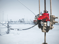 |
| Fig. 1. The intelligent rod rotator and load cell are stacked on top of the surface pump bridle. A cable is connected to the pumping unit to operate the rotator, while a signal cable is run from both devices to the rod-pump controller. |
|
A proprietary software application ties the signal into the rod pump controller. As part of the LOWIS life-of-well-information software—a web-based, well management and production optimization platform—the application tracks specific trends in the collected data. If two consecutive signals that are identical in numbers of rotation are detected, it indicates that the rod has stopped rotating. An alarm is then generated, both locally at the well site and remotely at the field office, indicating a rod-rotator failure and prompting the operator to deploy a team to the well to make necessary repairs.
The IRR system affords the operator deployment flexibility. The full system can be installed with the company’s WellPilot rod-pump controller system, or a modification kit can be installed on wells that already contain another rod rotator. This upgrade kit—consisting of a rotation sensor, sensing magnet and strap, mounting kit, load cell, and ancillary cables—enables operators to take advantage of the monitoring power of the new system, without having to completely discard the rod rotator that is already installed. Any real-time software package already in place to monitor the well can be used to detect the generated signal and track rod-rotator data.
According to Weatherford officials, in a recent field trial the monitoring system consistently and accurately notified the operator within 24 hours of a rod rotator failure. This was a significant improvement from the previous 3-to-4-week detection interval. The operator plans to expand field testing, motivated by the system’s ability to help prioritize maintenance activities, such that they could address rotator failures based on the productivity of the well.
Finally, the system enables an operator to develop and track key performance indicators that go beyond indicating whether or not the rotator is functioning. If the number of rotations recorded is lower than expected, the operator can make changes to increase system efficiency and avoid premature failure, thus avoiding a loss of production and, possibly, an expensive workover.
Capillary injection tubing anchor. Capillary injections of treatment chemicals—such as foaming agents, as well as corrosion, paraffin and scale inhibitors—help keep rod-pumped wells stable and producing at optimal rates. Pumping the right chemical down the well, in the exact location and quantity needed, can significantly lower the risks of premature workovers and lost production, thus reducing an operator’s extraction costs and operating expenses. Weatherford’s new Capillary Injection Tubing Anchor (Fig. 2) allows treatment chemicals to be injected with precision by improving the delivery pathway.
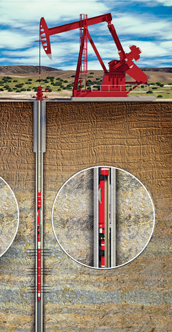 |
| Fig. 2. New Capillary Injection Tubing Anchor provides an improved delivery for treating chemicals. |
|
Traditional treatment methods that apply chemicals on the backside of the tubing sometime have as little as a 10:1 application-to-delivery ratio, meaning that only 10% is actually delivered to the desired treatment location. This severely limits the treatment’s effectiveness and raises the risk of constricted or halted flow, due to the buildup of scale and paraffin. Capillary systems provide an alternative delivery system, but still inject chemicals above the anchor. Weatherford’s tubing anchor is set above the pump and delivers treatment chemicals through a capillary string banded to the outside of the tubing for delivery of the treatment.
Designed to easily accommodate 41/2, 51/2 and 7-in. casing, this combination of tubing anchor and capillary string can reduce the amount of chemicals required to keep rod-pumped wells producing at optimum levels by 30% to 40%. Because the tubing anchor and capillary tubing work together to improve the chemical treatment delivery, they can help decrease operating costs and downtime by minimizing rod and tubing replacements. Expensive, time-consuming well interventions may also be reduced.
Chemical treatment of reservoir fluid is necessary in many wells to minimize operating cost. Getting the right chemical, in the right concentration, to the right spot for effective treatment, can be problematic or cost-prohibitive in many wells.
Treating chemical deployment tool. Basically there have been four methods for chemically treating producing wells: 1) dropping chemical “sticks” down the wellbore; 2) above-ground injection of chemicals into the wellbore from either chemical trucks or via a drip system; 3) pumping chemicals down the “backside” or casing annulus, and 4) using a capillary string (usually a ¼-in. alloy tube attached to the production tubing) to pump treating chemicals downhole at a precise location (see “Capillary injection tubing anchor” discussion above) .
Odessa Separator, Inc., a manufacturer of fluid conditioning equipment—primarily filtration and separation—has recently developed the Chem-Screen downhole treating chemical deployment system. The system consists of a specialized downhole chemical deployment tool (Fig. 3) pre-loaded with a proprietary blend of treating chemicals in solidified stick form, Fig. 4. The tool is run to the desired well depth on the bottom of the production tubing. Once introduced to fluid in the wellbore, the chemical stick gradually dissolves, allowing for a very slow release of treating chemicals that help control paraffin, scale and corrosion. Depending on well conditions, the chemical sticks typically yield eight or more months of steady chemical release.
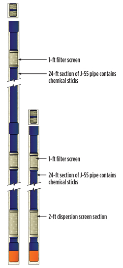 |
| Fig. 3. The 48-ft (left) and 24-ft (right) chemical deployment tools. |
|
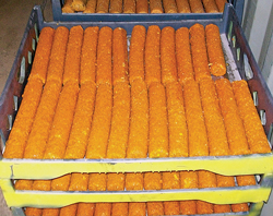 |
| Fig. 4. Solidified sticks of treating chemicals are designed to slowly dissolve downhole. |
|
Odessa Separator offers four chemical stick options. Stick selection depends on the specific well conditions and requirements. The basic stick, called the “Silver Bullet,” consists of a combination of chemicals designed to treat scale, corrosion and paraffin. The second stick also contains chemicals to combat scale and corrosion, but it includes an enhanced concentration of paraffin inhibitors (approximately 33% more than the basic stick). The third stick contains some corrosion inhibitor chemicals, but it is enriched with scale inhibitors. The fourth stick is specifically for corrosion treatment.
The tubing string deployment tool is manufactured with a 24-ft section of J-55 pipe base filled with the chemical stick. On the bottom of the tool, there is a 2-ft slip-on stainless steel screen over a perforated base pipe section. At the top there is a 1-ft, slip-on, stainless steel screen over a perforated base pipe section that helps eliminate any type of vacuum being created, so that the chemical stick can progressively slip down the inside lining of the tubing joint, as it is dispersed. More chemical can be deployed, over a longer period of time, by adding an additional 24-ft section of J-55 loaded with treating chemical sticks (i.e., for an overall tool length of 48 ft). This tool, manufactured in 23/8-in. and 27/8-in. OD sizes, can be adapted to most any tubing size and connection requirements.
This new chemical deployment system is not necessarily designed to replace existing batch or continuous liquid chemical treating programs. However, it can be an effective supplement to more traditional treating programs. It also can be an effective option, when surface treating methods become problematic or prohibitive, as may be encountered with high fluid levels, pumping below a packer or chemical treatment immediately after hydraulically fracturing the well.
This system has been deployed in approximately 800 wells across the Permian basin, Bakken shale and Elk Hills over the past nine months.
Beam/rod lift handbook. Some readers may find a new book of interest and useful. Entitled, The Beam Lift Handbook, 1st Ed., and authored by Dr. Paul M. Bommer and Dr. A. L. Podio, it is available from The University of Texas at Austin Petroleum Extension Service. This comprehensive volume outlines the four overarching goals of beam/rod pumping and presents the best practices for achieving these goals. The book covers important aspects of producing from wells using rod lift systems. It can serve as both a textbook and a field handbook. Using graphics, illustrations, mathematical equations and an online tool box, the handbook addresses the topic of correct use of beam/rod lift systems, and explains how to mitigate and avoid potential complications in daily operations.
POWER / CONTROL EFFICIENCIES
As previously mentioned, the costs to power artificial lift systems can be significant and, over time, can represent the highest cumulative cost of pumping a well. Artificial lift control systems have become increasingly important, since production downtime for any reason is very costly.
Not a microturbine. FlexEnergy’s turbine generators provide a low-maintenance, reliable alternative to the traditional reciprocating engine genset as a power platform for artificial lift.
“Microturbine is a term that connotes certain product features relevant to other industrial markets. We took a fundamentally different approach to our turbine design,” says Bob Campbell, President of FlexEnergy. “The term gas turbine (for FlexEnergy’s 250 kW and 333 kW turbine generators) more accurately reflects the traditional, conservative product that has served the oil and gas industry so well for decades.”
The heritage of these new gas turbines stems from the successful KG2 line of gas turbines manufactured by Dresser-Rand since the early 1970s. The design reflects the roots of the oil and gas power platform—a single centrifugal compressor coupled to a single radial turbine, driving a high load-capability synchronous generator through a speed reduction planetary gearbox. Reliable, low-maintenance, oil-lubricated rolling element bearings support the core engine’s high-speed rotor.
The Flex turbine (Fig. 5) is unique in its ability to manage cyclic loads with its synchronous generator and Generator Braking Resistor (GBR).
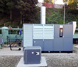 |
| Fig. 5. Oil field-ready Flex Turbine and GBR. |
|
“Our customers are most interested in operational reliability,” said John Alday, V.P. of Engineering. “Recognizing that downtime is extremely costly in an oilfield environment, we have designed a system that allows our turbine to maintain a constant speed and inertia while managing punishing cyclic loads, even those that regenerate (negative loads) for short periods.” This durable combination also allows the gas turbine to start motors direct-on-line in sizes up to 100 hp.
These turbines are durability-tested against customer’s load profiles in Flex’s Artificial Lift Load Management Environment. “We can simulate load surges that fluctuate 7 to10 times per minute,” said Alday.
Figure 6 shows pump loads recorded from a Bakken shale site before changes were made to the turbine and GBR controls. Figure 7 is a recording of cyclic pump loads applied to a Flex turbine with GBR compensation and tighter frequency control. “We have honed in on a design that allows for the turbine to operate within its comfort zone while serving a variety of load fluctuations” said Alday.
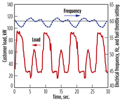 |
| Fig. 6. Actual site load at a well in North Dakota. |
|
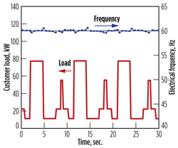 |
| Fig. 7. Load testing at FlexEnergy’s test site. |
|
This robust load following capability also has been applied to sites with multiple pumps.
FlexEnergy offers a durable solution for powering remote artificial lift, particularly for multi-well pads, where large fluctuating loads are commonplace. Multiple turbines can work together for larger applications and can consume virtually any flared or casing gas.
Regenerative VSD control. Power line regeneration has recently been a topic of discussion for oilfield applications, where it represents an economic and environmental advancement in variable speed drive (VSD) controlled pumping. Power consumption is expected to become even more significant as VSD-controlled production pumps are added increasingly to over-taxed grids. While large electrical utility providers have not required rod pump VSDs to meet low harmonic content by using energy more responsibly, utility co-ops operating constrained distribution grids, common in many oil producing areas, require consumers to maintain very low harmonics, Fig. 8.
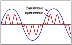 |
| Fig. 8. Harmonic content is a quality measurement of power. Because energy flows in sinusoidal waves, efficient use produces smooth waves (low harmonics), while less efficient use produces irregular waves (high harmonics). |
|
In recent years, VSDs have become the primary control devices for oilfield beam pumping units. Dynamic braking resistors (DBR) were added to early versions of VSDs to maintain tight speed regulation, slowing or stopping a motor by draining excess voltage to keep the pumping unit within safe levels. Although DBRs are functional, energy returning to the VSD during negative torque cycles is discharged through the DBR as heat (Fig. 9), creating losses in the 5% to15% range.
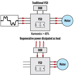 |
| Fig. 9. Traditional VSDs push power from the grid to the motor, but when energy returns to the VSD during a negative torque cycle, it is discharged through the DBR and cannot be recovered. Active Front Ends: unlike passive front ends, active front ends fill the voids in a typical energy wave cycle by anticipating and compensating for deficiencies during demand or release of power, so rod pumps don’t have to use such a large pulse to continue the flow of energy. |
|
Today, a greater demand for efficient operations and increasing pressure from power companies to reduce energy expenditure drives operators to finding solutions that improve productivity while conserving energy. VSDs with multi-pulse inputs have emerged and exhibit the capacity to reduce harmonics. New 12-pulse to 30-pulse drives can shift power output to lower harmonic frequencies. However, these solutions still incorporate a passive front end, requiring a DBR to burn off regenerated power returning from unbalanced pumping units.
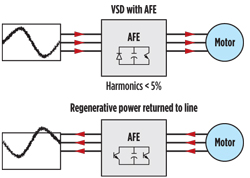 |
| Fig. 10. Adding a REGEN control to VSDs allows power to be harnessed during negative torque cycles and returned to the source for reuse. |
|
Adding a regenerative variable speed drive control, like Lufkin’s REGEN, to rod pumps is a low-maintenance solution that returns excess power back in its originally delivered state, when overhauling loads occur, Fig. 10. REGEN is like a hybrid vehicle with a rechargeable electrical motor. When a driver taps the brakes to slow the vehicle, the mechanical energy generated is converted back to electricity to recharge the car’s battery.
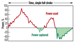 |
| Fig. 11. Power usage falling below the horizontal line is lost via a DBR during pump downstroke. The green area represents power captured for reuse by REGEN. |
|
As an active front end control, this new VSD control performs a similar function by returning power to the grid, where it can be used by nearby loads, Fig. 11. Harmonic content is automatically reduced to 5% or less, and the need for an outside, inefficient DBR is eliminated. The control’s programmable interface meets or exceeds rigid IEEE 519-1992 standards and continually monitors power while drawing it from the grid, only as needed. Direct control algorithms deliver full power to the pump while providing torque limits to reduce mechanical stress.
This technology has proven effective in production areas, where the local power grid mandates cleaner power consumption to reduce system stress. With 5% to 15% of electricity being lost to heat dissipation, this new control technology helps diminish the environmental footprint of onshore oil production while allowing producers to capture the benefits of VSD-controlled pumps. These benefits, coupled with reduced power consumption and lower operating costs, are attractive to industry producers.
The drive is currently available as a complete, integrated, rod-pump control solution, with 20- to125-hp ratings and an ambient temperature of -40°C to 55°C.
WELL MONITORING
In recent years, a growing emphasis has been placed on the timely monitoring, communicating and analyzing of well performance and production data.
New software and well monitoring equipment. Monitoring of a rod-pumped well’s performance from surface measurements of fluid level and dynamometer loads has been in use since the early 1930s. The original objective was only to observe whether fluid was present in the annulus above the pump and whether the pump was filled with liquid.
This tedious task—manually converting the distance of the echo travel time to the liquid level, and the load and position of the polished rod to a pump dynamometer diagram—was greatly improved and facilitated by the introduction of portable laptop computers in the early 1990s. There followed an evolution of computer programs for well performance data acquisition and analysis. Although greatly improved, these programs generally present quantitative results in terms of numeric and graphical values. However, accurate determination of the well’s performance still requires significant data interpretation by the user, who, in many instances, does not have the time or the necessary training to efficiently perform this analysis.
Echometer recently introduced a new generation of wireless hardware and software (the TAM total asset monitor) that greatly improves and facilitates data acquisition of fluid level and dynamometer data for analysis of well performance. By providing operators a real-time visualization of what is occurring in the well and in the downhole pump, it is possible to observe system performance directly instead of having to interpret numerical and graphical displays.
This software and hardware package takes advantage of the increase in laptop processing speed, memory size and screen resolution to generate, in real time, a quantitative visualization of the downhole rod pump operation, plunger motion, valve action and fluid flow.
An animation is presented simultaneously with the corresponding fluid distribution in the wellbore, obtained from the acoustic fluid level survey. This allows the user to see the complete performance of the well and lift system without having to interpret the conventional dynamometer card or fluid level record for the majority of wells that he monitors. The new system’s miniaturized wireless instrumentation increases measurement flexibility, eliminates inaccuracies caused by defective cables and connectors, and greatly speeds up installation and tear-down.
Real-time analysis and visualization of the performance of a rod-pumped well are achieved using multiple small and compact wireless sensors that simultaneously transmit acquired data to a digital laptop manager that integrates the measurements, displays performance graphs and provides advanced tools for analysis and troubleshooting of the pumping system.
Battery-powered wireless sensors (Figs. 12 and 13) for fluid level, pressure and dynamometer data acquisition are easily deployed and quickly installed on the well. The laptop manager (Fig. 14) automatically recognizes and commissions the sensors. The user sets up and controls the acquisition of data, which may include multiple sensors that synchronously monitor variables, such as tubing and casing pressures, fluid level and polished rod acceleration/position and load as a function of time. The user interface presents a smart instrument rather than a complex application.
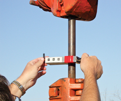 |
| Fig. 12. The wireless sensors employ long-life, rechargeable batteries. Typical range of over 450 ft has been achieved in most installations. |
|
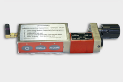 |
| Fig. 13. Wireless polished rod transducer. |
|
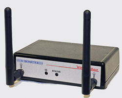 |
| Fig. 14. The wireless Echometer base station, with built-in well site GPS, connects to the USB port of a laptop computer and communicates with all wireless sensors. |
|
There are several advantages provided by these well performance analysis tools including:
the real-time visualization of the operation and fluid distribution in the downhole pump
the simultaneous display of quantitative surface and pump dynamometer graphs in conjunction with fluid level and wellbore pressures.
Acquired data, wellbore description and pumping system characteristics can be saved as a historical data base. This creates a continuum of the well's information and performance for direct comparison and detailed analysis.
Cable-to-surface downhole monitoring system. For monitoring in artificially lifted wells, Schlumberger’s Phoenix cable-to-surface (CTS) monitoring tools (Fig. 15) feature downhole sensors for in-depth diagnostics and analysis. The system can monitor beam/rod pumps, progressive cavity pumps (PCPs) and gas lift systems. The CTS gauges accurately identify operating problems or anomalies in real time, to facilitate effective intervention strategies, protect lift systems, improve well integrity, optimize production and maximize recovery.
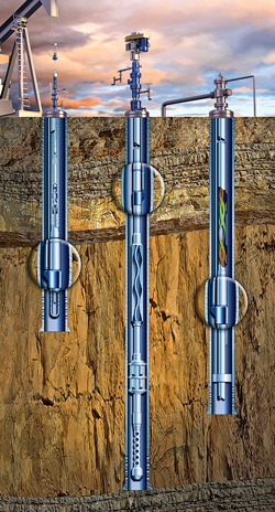 |
| Fig. 15. The Phoenix CTS system can be employed with beam/rod pump, PCP and gas lift system monitoring. |
|
The downhole gauge, which transmits data to the surface via an independent encapsulated clad instrument cable, monitors downhole parameters, such as intake pressure, temperature and three-axis vibration. Flexible parameter alarms provide warning detections to protect the lift system in the well. Operators can adjust the parameter alarms to the appropriate level of monitoring required. To monitor beam pumps, PCPs and gas lift systems, the gauge is mounted on the production tubing, either above or below the artificial lift equipment.
Advanced transducer technology, microelectronic components and digital telemetry ensure that the most reliable, accurate information is provided to operators, to enable thorough analysis of artificial lift performance. The gauge metrology allows data sampling every two seconds, providing critical measurements for pressure transient analysis. Trip and alarm relays for all monitored parameters are field-programmable to match individual conditions, therefore minimizing false alarms. Compatibility issues are reduced by using a single data acquisition and communications platform for all monitored wells.
The CTS monitoring system is fully compatible with other monitoring and control technologies. They are SCADA-ready, with a Modbus protocol terminal with RS-232 and RS-485 ports for continuous data output. This data can be further integrated with the Schlumberger LiftWatcher surveillance system for remote data acquisition, which provides alerts via satellite to facilitate the review and diagnosis of a variety of production problems.
HYDRAULIC PISTON PUMPS
Recently, there has been a number of hydraulically-driven piston pumps (HPP) introduced to the market. These systems require two or three separate lines to operate. Originally this was done via separate strings of coiled tubing. The introduction of the Flatpack (Fig. 16) vertical umbilical—multiple coiled tubing lines encapsulated in a vulcanized thermoplastic—by CJS Production Technologies has simplified the installation of these systems. This vertical umbilical can be configured in a multitude of arrangements and is installed via a conventional coiled tubing unit with a modified injection head.
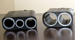 |
| Fig. 16. Flatpack vertical umbilical can accommodate multiple coiled tubing lines. |
|
The typical HPP is a dual-piston system that consists of a power end that is driven by the hydraulic fluid; a fluid end that pumps the well fluids; a rod connecting the two pistons; and a packing element to separate the two piston chambers. There are basically two different styles of pumps, one that utilizes two separate lines and one that features three separate lines.
The piston pumps that use two separate lines depend on gravity and fluid density differences for a portion of the pump cycle, therefore care must be taken to separate the gas from the produced fluid or the pump will gradient lock. One such pump is the HYGR (hydraulic gravity) from Hydro Pacific Pumps Inc. Pressure generated by a surface pump travels down the hydraulic line and moves the transfer piston upwards, lifting the column of well fluid in the product line. This action simultaneously draws fluid from the well into the lower chamber. When hydraulic pressure is released, the differential in hydrostatic pressure between the hydraulic fluid and produced well fluid and extra pressure as required, coupled with larger surface area at the top of the piston, forces it downward to refill for the next stroke.
The Lufkin ILS hydraulic submersible pump (HSP) is one of the three-line systems on the market. With the addition of the third line, there is no dependency on fluid density differences for the pump to function. The installation cost will increase, but if the wellbore configuration does not lend itself to efficient gas separation at the pump intake, it may be required to effectively pump a given well. The HSP can accommodate dewatering or conventional oil pumping at low volumes. It has been used successfully in coal bed methane (CBM) formations. It employs pressure generated by a surface pump, alternated between the two hydraulic lines; one driving the power piston down and the other driving the power piston up. The third line is used to convey the produced fluid to the surface.
Both styles are somewhat rate- and depth-limited, due primarily to the hydrostatic head applied across the packing elements. Typical production rates range from ~120 bopd at 1,000 ft and 50 bopd at 6,500 ft. These pumps do not require rods or downhole electrical motors and, therefore, can handle significant deviation.
NEXT MONTH
Part 2 of this year’s “What’s new in artificial lift?” series, in the coming June issue, will include an even greater number of recent product developments associated with ESPs, PCPs, surface jet pumps, gas lift and plunger lift systems. 
|
The author
JAMES F. LEA teaches courses in artificial lift and production for Petroskills. He holds BS and MS degrees in mechanical engineering from the University of Arkansas and a PhD from Southern Methodist University. Mr. Lea worked for Sun Oil as a research engineer from 1970 to 1975, taught at the University of Arkansas from 1975 to 1978, was team leader of production optimization and artificial lift at Amoco EPTG from 1979 to 1999 and was chairman of Texas Tech University’s petroleum engineering department from 1999 to 2006. He has contributed to this series for over 25 years.
HERALD W. WINKLER is former chairman and now a professor emeritus and research associate in Texas Tech University’s petroleum engineering department, in Lubbock, Texas. Mr. Winkler also works as a consultant to the oil and gas industry in artificial lift, specializing in gas lift. Early in his career, he worked for Atlantic Richfield and Camco. He, too, has contributed to this series for over 25 years.
JOE D. WOODS is president of International Pinpoint, a marketing and technical information company in Houston. Mr. Woods has over 35 years of energy industry experience. He was director of marketing and associate publisher at World Oil for over 12 years. Previously, he was vice president of marketing at GEO International Corporation. He also held key marketing positions at Halliburton and Texas Instruments. With Halliburton, he was instrumental in developing curriculum for the Modern Well Completion Practices School. He has written numerous articles on subjects such as expandable sand screens, intelligent wells, underbalanced drilling, drilling with casing, perforating, artificial lift systems, fracturing conductivity and proppants. Mr. Woods co-authored the Modern Sandface Completion Practices Handbook and the Mature Oil & Gas Wells Downhole Remediation Handbook. He attended Texas A&M University and received his bachelor's degree from the University of North Texas.
MARK S. GARRETT is a senior staff production engineer for Marathon Oil. Mr. Garrett has over 30 years of oilfield experience. His time in the oil patch has been spent as a production engineer and artificial lift specialist, spanning a number of production and service companies. He has worked around the world in a variety of field production environments, including CO2 floods, waterfloods, stripper production, gas well deliquification and unconventional plays. Early in his career, he was involved with innovations within both sucker rod and ESP lift, such as vibration analysis of downhole pumps and electronic dynamometer equipment. Mr. Garrett has taught courses within the industry covering ESP, beam/rod lift and lift system failure analysis. He has served on the Board of Directors for the ALRDC and the committee for the annual Gas Well Deliquification Workshop. He received his bachelor’s degree in petroleum engineering from the New Mexico Institute of Mining and Technology. |
|


