What’s new in artificial lift?
Part 2: In this second of two monthly reports, the authors highlight innovations in ESPs, PCPs, surface jet pumps, and gas lift and plunger lift systems.
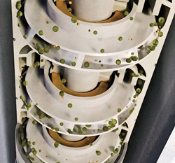
JAMES F. LEA, PL Tech LLC; HERALD W. WINKLER, Texas Tech University; JOE D. WOODS, International Pinpoint; and MARK S. GARRETT, Marathon OilESP DEVELOPMENTS Electric submersible pumps employ a multi-stage centrifugal pump at the tubing end. These pumps consist of rotating impellers and stationary diffusers that can be stacked in either floater or compression configurations, depending on performance requirements. Upon entering the pump intake, well fluids are subjected to large centrifugal forces caused by the high rotational speed of the impeller. The fluids lose their kinetic energy in the diffuser, where a conversion of kinetic to pressure energy takes place, with each impeller adding more head or pressure to the fluid. More impellers, therefore, are required for deeper wells An ESP downhole assembly will typically include the ESP pump, a gas handler/separator or standard intake, a seal section, a submersible motor with a connected power cable that runs to the surface, and, often, a downhole sensor package that communicates pump and wellbore performance information back to a surface interface system. The surface equipment may include a variable speed drive (VSD) or switchboard, a motor protection system and/or an intelligent control system designed for applications that require advanced system control and monitoring. This year, six new products related to ESP systems caught our attention. FLEX series pumps. Baker Hughes has introduced an innovative new ESP pump stage technology that addresses multiple problems facing unconventional oil wells. According to company officials, the Centrilift FLEX series pump line offers the widest operating range in the industry, with stage designs to handle dynamic well conditions and flowrates from 50 bopd to more than 10,000 bopd. The pump stages are designed for applications with a wide flow range, where gas and abrasives can be managed better with a mixed-flow design, Fig. 1. The pumps mitigate turbulence to reduce cycling and gas locking; balance thrust to reduce pump wear; and handle solids while minimizing plugging. Pump stages have a wider flow range than previous pump stages, so they can operate efficiently during dynamic reservoir conditions.
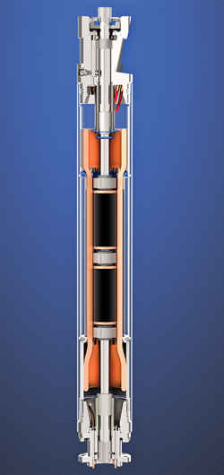
The new pumps are more efficient than previous designs, enabling shorter systems that are easier to place in near-horizontal well sections to further enhance productivity. Additionally, they allow for better well drawdown within a shorter system, providing higher efficiency and improved uptime by reducing cyclic shut downs. They also run with lower motor operating temperatures, which increases run life and delivers superior overall system efficiency. These pumps can deliver efficiency across a wide operating range, which may help to lower operating expenses (OPEX)—including power consumption—over the life of a reservoir. The FLEX pumps can improve reliability by providing stable operations in varying conditions. This is true of existing assets, as well as new production zones, like shale resource plays, tight reservoirs, and deeper zones—where flow conditions can change dramatically over short periods of time. They can handle thrust conditions more effectively than legacy pump models, which may increase run life and reduce workovers. With the ability to operate at lower flowrates, FLEX series ESPs provide a possible artificial lift alternative to some rod lift systems in unconventional shale oil applications. ESP systems have the potential to boost flowrates substantially before production stabilizes at a lower rate. To date, Baker Hughes has installed more than 1,000 ESP systems in unconventional oil wells. High-efficiency submersible motor. GE Oil & Gas Artificial Lift recently introduced the Enduro 45, a 4.56-in. outside diameter, high-efficiency submersible motor, Fig. 2. The new design incorporates a lamination configuration, rotor bearings and micro-filter system intended to provide longer service life. Operating at higher efficiencies, it provides more horsepower per rotor length than standard submersible motors. Fully compatible with the company’s current ESP products, the new motor offers an all-steel stator and shaped rotor bars designed to allow greater reliability and longer run-life.
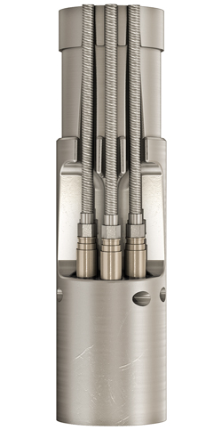
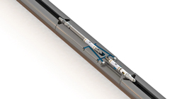
Non-rotating rotor bearings are designed to minimize bearing wear generated on start-up. The advanced snap ring configuration provides axial space for thermal expansion, serving to minimize wear, due to rotor bearing interference. Outboard rotor bearings stabilize the top and bottom rotors, eliminating the long lengths of unsupported shaft between the rotor bearings and the head or base bushings. This design feature contributes to reduced head/base bushing wear. Greater service life is also targeted with involute splines engineered to prevent motor-to-motor and motor-to-seal shafts from axially locking through the couplings while carrying torque. In addition, the all-steel, closed slot allows additional space for oil to flow axially through the stator, providing more cooling for the motor. The motor is available in 175-hp through 250-hp models. The company plans to release additional models later this year. Motor lead extension for extreme conditions. The new Trident motor lead extension (MLE) ESP connectors from Schlumberger feature a plug-in design aimed at improving reliability and eliminating errors, as well as saving rig time. The MLE connectors are designed with materials specifically selected and qualified to improve reliability in various applications, such as subsea, offshore, onshore high-profile wells and environments with a high presence of hydrogen sulfide. The system employs three individual polyetheretherketone-insulated (PEEK) copper conductor leads that plug directly into the downhole ESP motor, Fig. 3. This design minimizes the space required for the connector, in addition to providing greater heat dissipation during operation, and minimizing the need to manually manipulate the cable and connector during connection into the motor. The motor head design ensures that the MLE and individual connectors are protected from mechanical damage, while the ESP system is being lowered into the well.
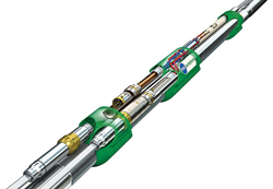
Test ports for each individual conductor verify sealing integrity during installation, before the system is run in hole. When combined with an ESP motor, such as the REDA Maximus 562 series, the MLE increases ESP system reliability and improves long-term dependable performance in power-demanding and run-life-critical applications. The high current-carrying capacity of the connector enables higher horsepower with less stator voltages and insulation stress than with traditional MLEs. With the Maximus 562 series motor and the Trident-400 MLE, up to 1,088 hp at 60 Hz are possible, using only two tandem sections and up to 1,170 hp with three tandem configurations. In addition to the Maximus 562, the MLEs can be combined with the REDA Maximus 738 series motors for applications that demand higher horsepower. According to the company, in Brazil the Maximus motor and Trident MLE combination has been successfully implemented in subsea applications. The combination is also being expanded to other offshore and land environments, with the goal of improving ESP reliability and performance. Innovative power cable switching tool for ESPs. Existing, dual-ESP completions require duplicated and costly specialized equipment to accommodate the two power cables necessary to separately control downhole ESPs. RMSpumptools’ THE SWITCH, a new, power cable switching tool (Fig. 4), provides a reported cost-saving alternative by changing how operators deploy dual- and multiple-ESP completions.
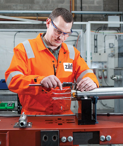
Traditionally, the power for dual-ESP-systems is supplied through two individual power cables, fed from the surface to each downhole ESP motor. Both power cables penetrate the wellhead through gas-tight wellhead penetrators. The two cables and specialized cable protectors continue downhole to the ESP setting depth. To provide annular isolation above the ESP systems, a production packer is often employed. Packer penetrators are used to maintain the packer’s critical pressure integrity. The packer penetrators transition the round, main ESP power cables to flat motor lead extensions. Then, the MLEs feed into the individual motors of each ESP, which can be configured in a choice of various ESP completion systems. RMSpumptools’ power cable switching tool introduces a new dimension to these established methods of dual-ESP completions. The switching tool is installed on the production tubing, typically below the pump packer. All cable terminations are factory-prepared to proprietary plug and socket connectors, thereby eliminating any field cable splicing, and ensuring high-integrity electrical assembly during installation. Employing proven RMSpumptools’ electrical and mechanical technology, the necessity for a second power cable is eliminated. Operation of the power cable switching tool is managed using traditional methods of hydraulic actuation from the surface. A single hydraulic line is all that is required to actuate the switching tool. Power to the downhole assembly must be shutoff before the switch tool is operated. Pressuring up the hydraulic line actuates the switch mechanism from its primary position to latch and lock in the secondary position. Pressuring up again releases the mechanism to return and lock into the primary position. The switch can be operated repeatedly by repeating this procedure. Advancements in ESP power cable technology construction and application now provide ESP systems with high run-life expectancy, upon which the switching tool capitalizes. With this tool, substantial benefits of dual and multiple ESP completions can deliver significant savings, less risk and greater flexibility. Elimination of thousands of feet of redundant power cable, alone, yields noticeable savings. Rigless ESP deployment. Historically, ESPs are powered by induction motors, which have improved considerably over the years. However, fundamental electro-magnetic flux density limitations of induction motors mean that there is an inherent compromise between power and tool size. It is often difficult to deliver the power required to lift the fluids, while simultaneously reducing the size of the induction motor. Accordingly, the size of induction motor-driven ESPs has historically dictated that systems be deployed downhole on the end of the tubing. By exploiting the compact, slim-line drive opportunities of permanent magnet (PM) drive technologies, Zilift’s SpeedDrive for ESP systems offers the capability to move away from conventional jointed tubing ESP deployment toward rigless through-tubing wireline and cable deployment. According to Zilift officials, the SpeedDrive (Fig. 5) is the only 25/8-in. diameter ESP motor on the market. Its smaller diameter allows the ESP system to be deployed through tubing in slim bore, live well intervention and restricted access applications.
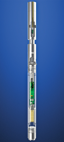
The use of AC synchronous, permanent magnet motors (PMM) to replace traditional induction motors enables a reduction in motor length and diameter for the same power output. This opportunity is made possible by the recent increases in permanent magnet flux density of PM materials, which removes the need for copper rods in the motor rotor assembly shaft and enables size reduction. Due to the inherent efficiency of a synchronous PMM, the ownership cost of the artificial lift system can be reduced, while enabling a reduction of system and power conduit size. Hence, smaller, high-efficiency tools enable versatile deployments. Additionally, a combination of PMM technology with variable frequency drive (VFD) systems enables smaller motors to provide higher work output. Effectively, this contributes to higher performance in a smaller package. New and improved downhole sensor. GE Oil & Gas Artificial Lift recently released the Osiris downhole sensor (Fig. 6), which can operate in both benign and corrosive environments. Standard metallurgy is 13 chrome, with high corrosion resistance and mechanical yield strength. This metallurgy eliminates the need for traditional external coatings and removes concerns about thin spots, flaking or coating damage that can result in localized corrosion and compromised operation during wellbore entry.
The sensor is available in either six- or seven-channel models. Six-channel sensors measure intake pressure, intake (reservoir) temperature, motor temperature, current leakage, longitudinal vibration and radial vibration. Selection of the seven-channel unit provides the addition of discharge pressure measurement. By measuring these downhole conditions, operators can potentially:
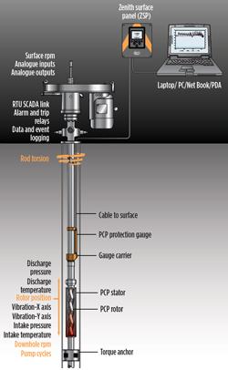
Data extracted from the sensor may be communicated to a customer SCADA system to provide remote monitoring and evaluation capability that can help in overall decision-making processes for well and production optimization. Prognostic approaches can help increase the reservoir’s production life cycle by alleviating formation damage caused by overproduction; help reduce downhole equipment wear and damage; and increase equipment run-life. PCP DEVELOPMENTS A progressive cavity pump (PCP) is a type of positive displacement pump. These pumps are also known as progressing cavity pumps, eccentric screw pumps or cavity pumps. As the pump’s rotor turns, PCPs transfer fluid through a sequence of small, fixed-shape discrete cavities. This leads to the volumetric flow rate being proportional to the rotation rate (bi-directionally) and to low levels of shearing being applied to the pumped fluid. The cavities of a PCP taper down toward their ends and overlap with their neighbors so that, in general, no flow pulsing is caused by the arrival of cavities at the outlet, other than that caused by compression of the fluid or pump components. Several recent product introductions related to PCPs follow. PCP protection system. U.K-headquartered Zenith Oilfield Technology, a Lufkin company, recently carried out installation and commissioning of an advanced, downhole PCP gauge in a well in Oman. The Zenith PCP protection system (Fig. 7) is a downhole gauge that contains a real-time, downhole, rotor position measurement. The technology eliminates space-out calculation variables, to ensure that the PCP components are installed in their optimum position. The parameters also continually monitor intake and discharge pressure, temperature, vibration, position, rod twist and downhole RPM.
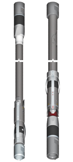
The system consists of a downhole gauge, gauge carrier and 0.25-in. I-wire control line deployed as a standard permanent gauge within the tubing string. The Oman installation also contained a rod shaft array that is deployed between the rod string and the PCP rotor to generate a position and movement signal, which the downhole gauge on the outside of the tubing can monitor. The surface package consists of a data acquisition panel and magnetic pick-ups mounted on the PCP top drive to monitor both directions of rod turn. The downhole position measurement is used to remove all ambiguity of rotor position versus tag bar depth, pull-back requirements to counter rod stretch and actual final position of the rotor after settling time. Preliminary findings before start-up of the Oman well presented a number of interesting results. Following installation of the PCP drive head, the gauge data showed the actual amount of downward rotor movement toward the tag bar, due to rod stretch in the static well. When the PCP was started, the rods continued to stretch, due to increasing differential pressure across the pump. It was noted that an increase in speed would likely cause the rotor base to “ride” on the tag bar, as the rods stretched with increased tensile loading. The position data were used to re-space the rotor very easily, as the rod string could be pulled back without the need for the top drive to be removed. The PCP rotor was lifted, using a flush-by unit, with the gauge data used to accurately monitor the repositioning. The actual position of the base of the rotor could be seen in real time, allowing the crew to accurately place the rotor to counter for rod stretch without having to perform a full space-out procedure. The rotor position measurement from the protection system highlighted issues and ambiguity with the pull-back procedure, and also subsequently protected the base of the rotor “riding” on the PCP tag bar to avoid a premature failure of the PCP system. It was noted that incorrect rotor positioning had contributed to numerous issues with earlier PCP installations. Insertable PCP anchor. Weatherford’s Flexisert I-PCP anchor (Fig. 8) advances insert progressive cavity pump technology by enabling the pumps to be installed in any convenient location in wells not equipped with a pump seating nipple (PSN). The anchor allows insert PCPs to be run, landed, operated and removed without pulling the tubing string, thus enabling cost savings associated with well servicing time and pump changes.
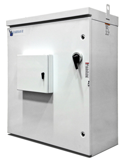
In one trip, the anchor can be deployed into the tubing string, to allow changes in the pump setting depth, pump volume and lift capacity. Downhole monitoring equipment can remain in place during pump servicing. Cost-saving advantages are attributed to the unique design of the anchor, which incorporates several critical functions, such as preventing pump rotation; providing a seal between the pump intake and high-pressure discharge; and preventing axial movement of the pump, due to pressure differential across the anchor’s seal. The anchor is available for 27/8-in. and 31/2-in. production tubing, where insertable PCP anchors are applicable and no provision for a conventionally deployed, nipple-seated insert pump is available. The anchor can pass through common tubing restrictions, such as a PSN and subsurface safety valves. It also provides an effective solution, when a PSN with unknown specifications is installed or located incorrectly. The result is an insertable PCP system that provides a compact, practical solution for reducing nonproductive time and costs associated with pulling tubing when changing or replacing a tubing-installed PCP anchor. PCP automation, control and monitoring solutions. Numerous variables, including pump efficiency, pump age, fluid properties and reservoir behavior affect control (pump speed) decisions. As a result, PCP controllers need to adjust speed by taking these variables into account for two key reasons—protecting from pump-off condition and ensuring maximum fluid removal. Overall, artificial lift innovations are targeted at optimizing well production by monitoring, communicating and controlling PCP systems for more accurate and cost-effective performance. Key examples include: remote access to real-time pump monitoring and control; transmitting real-time performance information; interactive communication between operator and well; diagnostic logic and control functionality; maximizing pump performance and well production; and reducing on-site operator intervention. NOV’s Guardian automation solutions package includes a variable speed drive (VSD) (Fig. 9) with capabilities aimed at achieving the best possible efficiency and PCP control; rod string and pump protection from potential torque problems; user-friendly interfaces; simple implementation into SCADA; adaptability to virtually any legacy system; and holding critical downtime to a minimum.
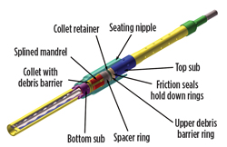
Other packaged components included downhole and surface sensors. The sensors help operators improve pump performance and total well production by monitoring real-time downhole pressure and temperature, transmitting data downhole to the surface, and altering the pump speed automatically, according to changes in well conditions. Additionally, by using the NOV “Communicate Now” satellite technology, pump performance can be monitored and controlled in real time. The monitoring system requires no infrastructure build-out; only standard, quick set-up installation and implementation, even in remote locations amid harsh conditions. The system allows secure reporting into the host site and requires no special skills to install or operate. The web-based software package can be used to track operating details, and to store relevant information, visuals or other files, and can define multiple warning and alarm settings. It also allows quick adjustments of operating parameters. It can facilitate daily status reports and send alarms via e-mail and smart phones. Above all, the software suite systematically acquires real-time data, maintains two-way operator/pump communication and is a central repository for well information. Designed to meet the same set of objectives on a real-time basis, these automation solutions can provide quick assessment capability for well conditions and pump performance. By not being locked into one implementation approach, operators can opt either for installation on their company computer system, or a turnkey solution designed around a secure web-based application. Universal pump hold-down system. With progressive cavity pumps continuing to be a significant artificial lift solution, fine-tuning a key operational aspect became an important design challenge. NOV engineers developed the universal pump hold-down (UPHD) system (Fig. 10) that allows a conventional reciprocating rod pump or rotational PCP to be installed interchangeably into the same seating nipple, potentially saving time and money.
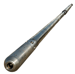
This enhanced capability is especially ideal, when a well’s thermal profile changes (temperature becomes excessive) either during oil production or steam injection, which previously made a pump change necessary and forced the tubing string to be pulled. With the UPHD system, that extra on-site “make work” has been rendered obsolete. Additionally, while insert systems are not a radically new invention, this specific system’s innovation solves previous design shortcomings, says NOV. For example, its releasing mechanism is engineered to be isolated from the well fluids and particulates or sand build-up. Therefore, it helps to ensure that retrieval is neither partially hindered nor completely blocked. Featuring a one-piece nipple and inner mandrel, the UPHD installation procedure involves: 1) set down to install; and 2) straight pull to retrieve; no orientation or rod manipulation must be done. The latter is particularly critical, because it ensures that any pump can always be retrieved, even if internally seized. Other features include: the improved, patented and field-proven metal-to-metal hold down sealing rings; the system is quickly and easily configured for either top or bottom hold down; it is well-suited both for deviated wellbores and sour environments; and either type of pump can be inserted into the seating nipple. Downhole PCP drive system. Zilift’s TorqueDrive (Fig. 11) is an innovative downhole drive PMM (Permanent Magnet Motor) PCP system that brings all the advantages of affordable, downhole, electrical pumping technology—power efficiency, pump placement and drive delivered to the pump, at the pump—to low-flow, slim-bore, high solids, deviated and horizontal applications. The system aims to reduce lifetime lifting costs; extend economic production life; produce with high gas, sand or solid content; and produce the reservoir more steadily for a longer time.
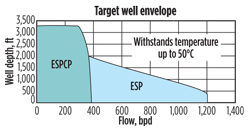
PCPs have proven to be a simple, robust lifting solution, particularly at lower flowrates, combined with higher solids in heavy oil, in gas well deliquification, and in shale and coalbed methane (CBM) applications. PCPs have traditionally been driven from the surface via a rod system. This approach is effective, but it has a number of significant drawbacks, including inherent power inefficiency; diminishing returns based on the depth of the well; pump placement compromises; monitoring challenges; pump operating window compromises; failures, due to friction and rod separation; environmental impact of hydrocarbons at the surface; noise, visual pollution, etc. With the TorqueDrive system, it is possible to deploy a PCP, and remove the compromises and failure modes associated with top drive systems. TorqueDrive delivers power directly to the PCP downhole, utilizing efficient permanent magnetic motors and an innovative torque converter. ESPCP dewatering solution for gas wells with low flows. In shallow gas well product applications—such as CBM and shale gas—gas is trapped in formations by water pressure. The wells must be dewatered before they can produce. Dewatering operations require dependable, efficient pumping systems that can withstand abrasive solutes and operate at controllable flows, in order to maintain production and minimize downtime. Conventional water well ESPs are beneficial, if the well meets a certain set of conditions. They are good for applications involving relatively shallow depths (less than 2,000 ft), and can handle high flowrates. Because they’re submersible, ESPs are often considered more efficient than pumps that require above-ground motors that drive the pump through a long rod string, which may be prone to wear or breakage, particularly in deviated wells. However, ESPs begin to lose efficiency in wells producing less than 150 bpd, and can break down when they encounter solids, sludge or gas. According to Franklin Electric, the ESPCP (electric submersible progressing cavity pump) lift system shares the advantages of a submersible system, and goes beyond water well ESPs in capability for deep wells and low flows. With a design that was originally developed for mining applications, where water was often full of sludge and harsh mineral deposits, the ESPCP is built to be abrasion-resistant and to handle a variety of well conditions, such as paraffin-based compounds. Unlike the performance of a traditional centrifugal pump—for which both flow and pressure vary with speed—PCPs operate by forming a seal surrounding a fixed cavity that progresses along the pump as it turns, making the flow proportional to the speed. However, the pressure is independent of speed. Hence, PCPs can efficiently operate over a large flow range and greater depths, Fig. 12.
Another advantage of being tightly coupled to submersible motors is the fact that ESPCPs respond very quickly to inputs from surface drive and control systems. Conversely, Franklin’s Drive and Control System (Fig. 13) can respond very quickly to changes in the well, to protect the pump and motor.
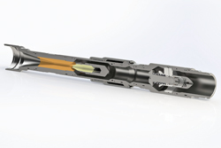
Shaft-driven pumps impose time delays and sensitivity limitations in detecting these changes in the well. Franklin’s control system presents the operator with a user-friendly interface, enabling the operator to set operating modes, configure protection mechanisms and log data without having to be a controls expert. The system’s common terminology allows operators to choose either standard or user-definable input/output options for a variety of sensors, and to easily set well control parameters to fit the needs of the application. New PCP software tools. French firm PCM has released new design software, PCM Design, for the selection, evaluation and optimization of PCP artificial lift systems. Data management is increasingly important to operators. Informed decision-making based on clear, concise and timely data can help operators maximize well potential, comprehend a PCP system’s behavior for custom optimization along its life cycle, and ensure that the system is accurately sized (motor, drive head, rod string, pump). According to PCM officials, their web-based design software helps operators manage PCP system data by field, well and case. The simulation mode of this new software is used to design and optimize PCP artificial lift systems with theoretical performances (as per manufacturer specification) or real performances (using test bench results). In the evaluation mode, operators can evaluate or monitor PCP performances after installation downhole. Results are illustrated by indicators and warning messages that underscore system performance. A comprehensive report-generating function with a detailed graphics package also aids in data management and decision-making. The design software solution has been developed for completion designs, system analysis, evaluations, and optimization of any PCP system. The software includes modules for hydraulic regulator progressive cavity pumps (HRPCP) and all metal progressive cavity pumps (AMPCP). Additionally, a rod string centralizer module is available to optimize the centralizer distribution along the rod string, based on contact load with the tubing. This software will allow users to proceed to a direct automatic selection, or a manual selection, if desired. Once the rod string centralizer positioning design is complete, the user can edit the associated tally while preparing for well installation. In addition to developing the design and evaluation software package used during the full life cycle of a PCP lift system, the company has developed an equipment field tracking software solution, Field Track. It can be used to follow new technology in oil and gas applications, from prototype validation to pilot implementation and field deployment. PCM believes that following artificial lift pilot programs—in different fields on different continents with different teams—necessitates a common method of identifying relevant data, understanding the data and organizing the data for better decision-making. SURFACE JET PUMPS Surface jet pumps (SJP) use a high-pressure source to create a low-pressure zone, where other (low-pressure) fluids can be drawn in and mixed. The combined flow is then discharged at an intermediate pressure. Hence, the SJP uses the available pressure energy in a fluid to do work on a second fluid to boost its pressure. As a passive device with no moving parts, a jet pump needs very little maintenance or control. Yet, it can be very effective at harnessing existing energy sources, such as a compressor on recycle or a high-pressure well, to boost the production rate and/or delivery pressure of low-pressure wells. Jet-pumped well integrity enhancement. Norwegian oilfield technology specialist PTC, which until now has made its name in artificial lift for developing well barrier-accredited gas lift valves, has developed two new solutions to issues associated with hydraulic jet pumps. With hydraulic jet pumps, the potential exists for tubing-to-annulus communication (reverse flow through the nozzle), when the well is not operating under jet pump lift and is either closed-in or flowing naturally. Historically, this challenge has been addressed by deploying a simple floating check valve in the jet pump nozzle. However, operators are increasingly demanding verification that these check valve devices are well barrier-accredited and do not potentially become the weak link in the primary well integrity envelope. PTC’s solution is a safety valve module, attached to the bottom of the jet pump module, Fig. 14. The overall length of the jet pump and safety valve modules is less than 5 ft. The assembly can be installed and retrieved on slickline, either hung off in a sliding sleeve or as part of a straddle assembly. As the safety valve is actuated by power fluid pressure, the valve does not chatter in the flowstream. The safety valve is taken directly from the PTC water injection check valve product, is field-proven, and has been verified to V1 leak rate.
This solution, which results in the well’s primary containment envelope being below the jet pump, also provides assurance that the check valve performance will not deteriorate over time. It, therefore, represents a significant enhancement, when compared to the floating check valve in the nozzle, which could have a tendency to chatter and/or become eroded in the flow stream. A shear sleeve feature has also been incorporated, meaning the annulus can be pressure-tested prior to pumping. While this solution assures well integrity when the well is closed in, it does preclude the possibility of natural flow. This functionality can be important, especially in applications, where the jet pump is only required temporarily or intermittently. A good example is in gas well deliquification applications, where the jet pump’s tolerance of alternating gas and liquid flow is a significant differentiator when compared to other lift methods. To address the latter challenge, PTC has developed a solution, where a power fluid-actuated, metal-to-metal seal, sliding-sleeve isolates tubing-annulus communication. In this case, the safety valve module is not required below the jet pump, so natural flow through the jet pump is possible without compromising tubing integrity. Jet-pumped, well performance simulation software. PTC also has developed a jet pump well performance simulator that is free to use online, via its website (www.ptc.as). The tool can evaluate the likely well performance under jet pump lift. It also provides answers to the frequently asked questions associated with jet pumping, such as: How much power fluid will be required; and how does the power fluid requirement vary as a function of power fluid pressure? Surface jet pump application for gas lift wells. Gas lift is an effective method to increase production, or to enable wells to produce effectively by lowering the hydrostatic head of produced fluids. However, there are a few issues that can impact gas lift effectiveness. These include:
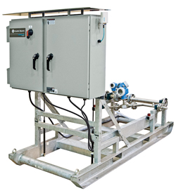
These issues, combined with depletion in the reservoir pressure and an increase in water-cut during the life of the field, can cause further restriction of production from all wells, including gas-lifted wells. In such situations, reducing the flowing wellhead pressure (FWHP) can complement the gas lift system, which can lead to further increases in production and extend the well’s life. Lowering the FWHP demands a boosting system. There are a number of ways to reduce FWHP, such as use of multiphase pumps or by lowering the operating pressure of the downstream process system. One simple, cost-effective solution, according to officials at Caltec Ltd., involves using a surface jet pump. Depending on the application, the power fluid for the SJP can be either available, high-pressure gas or liquid.
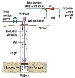
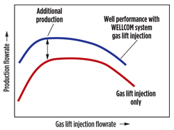
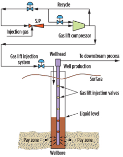
Figure 15 shows a typical installation for a gas-lifted well, supplemented with an SJP. In Fig.16, the gas- lift curve (red-colored line) shows how increasing the rate of the lift gas becomes ineffective beyond an optimum rate. The blue curve shows how reducing the well’s FWHP by using an SJP system can increase production, even if the gas lift rate is below its optimum.
Figure 17 shows another application of SJPs, when the available gas lift pressure is below the required value for injecting gas at the deepest part of the well. In this case, the SJP system is installed upstream of the gas compression system. Some of the high-pressure gas, such as the recycled gas from the compression system, can be used to power the SJP. The SJP increases the pressure of gas entering the compressor. This, in turn, will lead to an increase in the compressor’s outlet pressure. The higher pressure gas is then injected in the deepest part of the well, where it is needed.
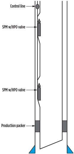
The SJP has several benefits compared to alternative systems, which can reduce the FWHP of a gas-lifted well not equipped with a gas lift system. The benefits include compactness, low CAPEX, and no moving parts. Hence, there is essentially no maintenance requirement. The system does not require active control or operator intervention, making it applicable for unmanned satellite platforms. According to Caltec, the use of an SJP system should be considered, when wells are required to operate at a lower FWHP to optimize production, or in some applications to prevent wells from liquid loading. GAS LIFT In the U.S., gas lift systems are used in about 10% of oil wells that have insufficient reservoir pressure to produce naturally. The process involves injecting gas through the tubing-casing annulus. Injected gas aerates the fluid to reduce its density; the formation pressure is then able to lift the fluid column and force it up the wellbore. Depending on the well’s producing characteristics and the specific characteristics of the gas-lift equipment, gas may be injected continuously or intermittently. Hydraulic control-line operated gas lift valves. PTC has developed a new patent-pending, hydraulic control line-operated, gas lift valve system, Fig. 18. It uses PTC standard, retrievable injection pressure-operated (IPO) gas lift valves, and side pocket mandrels with only minor modifications. The system allows for selective opening and closing of up to nine gas lift valves in a completion, delivering:
Dual, retrievable, check valve side pocket mandrels. Another new device from PTC is a patent-pending side pocket mandrel (SPM) system, which accommodates a conventional, retrievable gas lift valve, and a gas lift check valve, in series. The system utilizes both upward- and downward-facing pockets, Fig. 19. Lift gas enters the SPM via the downward-facing check valve and is ported within the SPM to the conventional upper valve.
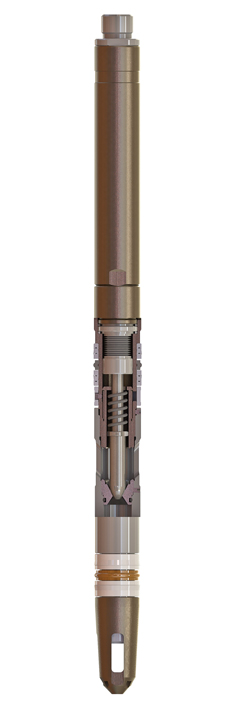
If the upper valve has to be changed out, the check valve remains in place. This helps maintain well integrity and eliminates the potential for u-tubing. The system is differentiated, in that the check valve is also retrievable (using an upside-down kickover tool) without the need for a full workover. IPO valve can be used as operating valve. PTC’s family of injection pressure-operated (IPO) unloading valves (Fig. 20) employs a patented, double-acting bellows design, which is rated to 10,000 psi.
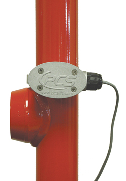
Despite this high-pressure rating, the unique design of the bellows facilitates an unusually long valve stem travel. Consequently, the valves can withstand higher unloading rates than traditional valves, helping to reduce completion commissioning and installation time. The unusually long bellows travel also means that the valve suffers very little from throttling. The unloading valve is essentially invisible to flow when fully open. Consequently, the option exists to use shallow-set IPO unloading valves for long-term gas lifting—essentially as an intervention-free alternative to the deep set operating valve for cases where reservoir conditions are uncertain, or operating conditions unexpectedly change. This option has already been used in a number of subsea wells in the North Sea, potentially saving operators expensive well intervention costs. PLUNGER LIFT DEVELOPMENTS As an artificial lift method, plunger lift falls into the flow enhancement category. It makes use of a well’s own energy (gas and/or pressure) to lift accumulated fluids from the tubing and annulus. A plunger utilizes an interface seal between fluid in the tubing and stored gas in the annulus. The head gas is blown down, creating differential pressure across the plunger, which pushes both the plunger and accumulated fluid to the surface. New plunger arrival sensor. PCS Ferguson recently introduced its 3DSO plunger arrival sensor for plunger lift wells. As an integral part of a plunger lift system, the plunger arrival sensor is mounted to the surface lubricator, detects the plunger’s arrival and then activates the controller to the appropriate mode for optimal well production. Historically, arrival sensors have relied on passive, single-coil sensing technology and could only detect a plunger, if it arrived quickly and at a particular angle. This new plunger arrival sensor features proprietary 3-D technology that allows the sensor to detect a plunger’s arrival in three axes, regardless of the plunger’s arrival speed or angle. It can even detect an arrival, when the plunger is stopped in front of the sensor. Whereas environmental conditions may cause interference with traditional arrival sensors, this sensor features an embedded microprocessor that continually self-calibrates to filter out environmental “noise,” to ensure accurate arrival detection and eliminate false reporting. It is virtually maintenance-free, which helps reduce operator intervention and production downtime.
The plunger arrival sensor (Fig. 21) features an aluminum housing designed to protect the unit from harsh weather conditions. The housing won’t flex during installation. All the electronic components are potted to prevent moisture penetration, and every sensor undergoes a 25-point electronic test before it leaves the factory, to ensure product quality and reliability.
|

