JOHN CAMERON, Enventure Global Technology
 |
| Solid expandable and elastomer technologies optimize refracturing programs by creating new perforation intervals. |
|
Many times, a well that must be hydraulically fractured to be economic will experience a production decline that will make attaining the well’s estimated ultimate recovery (EUR) impossible. In unconventional reservoirs, such as shales with long laterals requiring multiple frac stages, it is often more economical to refracture the same lateral wellbore, rather than to drill a new well. In shale reservoirs, it is common to shoot 1-to-3-ft perforation clusters, with four to six phased shots per ft (13 to 20 shots per m), with clusters spaced greater than 50 ft (15.2 m) apart.
To effectively refracture the well, it is desirable to at least restimulate all the old perforations, but it is preferable to seal them off, and shoot new perforation clusters between them, especially for widely spaced perf clusters. A common way of doing this is to squeeze off all the old perforations with cement, drill out the cement from the wellbore, and conduct a standard plug-and-perf frac treatment from the toe to the heel of the well, perforating between the old perforations. This may work, assuming the cemented perforations, especially near the heel of the well where frac pressures are highest, hold up.
Other methods of refracturing use diverters, such as 100 mesh sand, rock salt, perforation ball sealers, benzoic acid flakes and biodegradable particulates.¹ These are designed to plug the perforations, taking the most flow, thereby diverting flow to other perforations to get a more uniform injection of fracturing fluid and proppant along the lateral. These are also designed to unplug the perforations during flowback, to allow production from all the perforations.
Refracturing has been done in shale oil wells with uncemented liners, using methods that include the “pump-and-pray” method, where fracturing fluid slurry is bullheaded into the formation through the perforations or fracports. Wells initially fractured using this method are thought to be good candidates for refracs, which would imply they were understimulated initially.² It is interesting, however, that, anecdotally, at least one operator has also had successful refracs using this method in the Bakken.
The other extreme is the use of mechanical isolation, such as a liner and packers placed in the well at locations to provide isolation for each frac stage from the old perforations uphole. However, this method using conventional packers and liners can severely reduce the effective ID of the wellbore available for refracturing operations.³
For instance, for the refrac in a 5½-in., 17-lb/ft casing with an ID of 4.892-in., the use of a 3½-in. conventional liner with swellable elastomers would result in an available drift of 2.992 in., compared with a post-expanded drift of 4.151 in., when using the expandable 4¼-in. liner. The solid-steel expandable liner would give ample room to run the large guns necessary for perforating two strings, as well as the coiled tubing for drilling out the frac plugs.
BARNETT SHALE BACKGROUND
The Barnett is one of the largest shale gas plays in the U.S., with 43 Tcf of technically recoverable gas reserves, of which about 7 Tcf have been recovered as of 2010.4, 5 Annual production was about 0.7 Tcf by 2010. However, with the drop in gas prices after 2007, gas production is expected to level off, or fall, as operators stop drilling new gas wells and even shut in existing wells. The Barnett was a game-changing shale gas development in the U.S., where Mitchell Energy and Development experimented during the 1980s and 1990s, to commercialize shale gas production in North-Central Texas.
The technology developed was the advent of multi-staged fracturing treatments of predominately horizontal wells, which created hydraulic fractures running perpendicular to the lateral wellbore. In the Barnett, laterals range in length from 2,500 to 3,500 ft, although lengths as long as 5,000 ft have been drilled. Barnett laterals are usually cased and cemented using 5½-in. casing, and hydraulically fractured using the plug-and-perf method, with multiple frac stages. Each frac stage is perforated with multiple perforation clusters where fractures are initiated. Over time, spacing of hydraulic fractures has become smaller, and, today, the spacing of hydraulic fractures, or perforation clusters, is usually as narrow as 50 ft.
Barnett wells have been fractured with either cross-linked gels, to get wider fractures and to carry more proppant (100 mesh to 20/40 mesh sand), or with water containing drag-reducing additives (slick water), to allow high pumping rates to better enable proppant transport, and to encourage multiple fracture development. Presently, slick water is used more in shale gas plays, while cross-linked gels are used more in shale oil plays. A typical slickwater frac in the Barnett shale consists of 500,000 to 6 million gal of fluid, 80,000 to 1.0 million lb of sand, and pumps at rates of 50 to 100 bbl/min.6 Greater quantities of fluid and proppant are used in horizontal Barnett wells, as opposed to vertical Barnett wells.
Figure 1 shows the location of the Barnett shale in the Fort Worth basin and its neighboring stratigraphy. Fracture barriers are necessary in the Barnett shale, to control fracture height, so that fracture network creation will be maximized and the induced fractures will be kept from intersecting any nearby water-bearing unit, such as the Ellenburger formation. Water encroachment into the Barnett from the underlying Ellenburger can be a significant problem. The Viola-Simpson limestone formation that lies between the Barnett and the Ellenburger helps to provide a barrier to the downward growth of hydraulic fractures.6
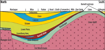 |
| Fig. 1. Cross-section of the Fort Worth basin in North-Central Texas showing the Barnett shale.6 |
|
Initial production of a Barnett horizontal gas well typically ranges from 1.6 MMcfgd to 2.5 MMcfgd, with well EUR of 2.4 Bcf to 3.5 Bcf. Declines in production can be 50% to 55% during the first year for a Barnett horizontal well.⁶ When determining good well candidates for refracturing, one should consider other factors outside of production decline. Reservoir quality and completions effectiveness, including the azimuth of the fracture, should also be considered.2,7
In the Barnett shale, refracs have been successful, especially when wells that were originally fractured with gelled fluids or foams have been refractured with slick water. This was demonstrated in the second refrac of the Mitchell Energy “discovery” shale well using slick water, where the initial post-refrac production was triple that of the initial frac using foam and the first refrac using gelled fluid.8 This is attributed to the slick water bypassing polymer damage, opening smaller fractures than gelled fluid could, and extending the fracture system more, because of the larger quantities of slick water used.8 When new areas in the shale are exposed by a refrac, especially if re-perforated in new locations in the lateral, there should also be a gain in reserves.
SOLID EXPANDABLE TECHNOLOGY
There are several commercial processes for expanding solid-steel liner downhole for wellbore repair and perforation isolation.9 All of these use some form of hydraulic pressure and/or mechanical force to expand the liner, and/or sealing elements downhole at in-situ temperature and hydrostatic pressure conditions. The process used in this work is a hydraulically-pressured, cone-driven expansion assisted by mechanical pull from the inner string running from the rig floor to the top of the cone, as shown in Fig. 2. Clean fluid pumped behind the cone through the innerstring exerts hydraulic pressure behind the cone, which is machined using specially formulated, hardened steel. In addition, pull applied to the innerstring can increase the force available for the expansion. When the net stress applied to the liner exceeds its yield stress, the liner will start deforming in the plastic region of the stress-stain envelope, in a cold-working manner. The cone angle and size is designed such that the total deformation of the liner does not exceed the strain that creates the ultimate stress necessary for the material to fail. The liner strength actually increases during expansion, although the remaining ductility is reduced.
The tubing used for expandable liners is manufactured using electric resistance welding (ERW) and a special quality steel. This steel is designed to match the strength properties of L-80 steel, with enhanced expansion properties. For refracturing purposes, the usual sizes are 4¼ in. for use in 5½-in. base casing, and 5½ in. for use in 7-in. base casing. For higher pressure and temperature applications, and for the smallest size base casing, 4½ in., special partially expandable systems or single-joint liners, where connections do not have to be expanded, have been designed using 110-ksi-rated materials. This article considers the application of refrac liners for the Barnett shale and other shale formations, where temperatures and refrac pressures are moderate enough to allow the use of liner with strength properties comparable to L-80, as well as connections with standard tensile loading ratings.
The top photo in Fig. 2 shows a liner in the process of expansion. The amount of increase in ID during expansion varies from 5% to 18%, and depends on the size and weight of the base casing. However, expansions have been done successfully above 20%. Wall thickness decreases during the expansion, usually by less than 4%. During the expansion, the liner also shrinks in length by a small amount, usually less than 5%. The illustration in the lower part of Fig. 2 shows seals, both uncompressed and compressed, after expansion. The compressed seals support the liner in the base casing and provide isolation for frac stages. These also provide isolation from unwanted perforations, as well as from casing damage. Cone expansion takes place at rates from 30 to 15 ft/min, although the effective rate is less when taking into account the time for disconnecting and laying down workstring joints. An internal lubricant is coated on the inner surface of the liner to minimize cone friction during expansion. Sometimes, a secondary lubricant is added to the wellbore fluid, to assist in running the expandable liner into the wellbore. A special connection sleeve is installed with each connection, to protect it from being damaged while running in the wellbore. This sleeve is usually 0.04 in. thick, adding 0.08 in. to the OD, which should be less than the drift of the base casing.
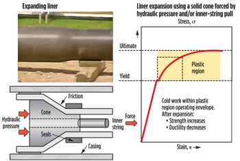 |
| Fig. 2. Cone-driven expansion using hydraulic pressure and/or inner-string pull. |
|
This expandable liner process was first successfully implemented in 1998, and it has undergone upgrades and refinements. Presently, solid expandable solutions have been constructed and installed for applications requiring: lengths to 6,935 ft, seals for temperatures to 400°F (with special applications up to 518°F); up to 20 ppg mud weight; installations to depths of 28,750 ft, MD; and installations in wells with inclinations up to 100°.
Description of the well and expandable liner. The refrac liner used in the first case history was installed in the lateral section of a horizontal well in the Barnett shale, referred to here as Well #1. This well has 10,730 ft of 5½-in., 17-lb/ft, N-80 production casing. Well #1 has a total length of approximately 10,800 ft, MD, and a TVD of approximately 7,000 ft. The well was initially completed with perforation clusters in the lateral section from 7,633 to 10,628 ft, spaced about 100 ft apart. The initial fracturing treatment was done in four stages, with total volumes of 32,000 gal of acid and 1.6 million gal of slick water, and 713,000 lb of frac sand.
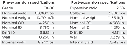
Well #1 was produced for three years, during which time production dropped from a peak rate of 2.6 MMcfgd to 0.4 MMcfgd, after which the decision was made to re-fracture the well. Mechanical isolation of perforations was designed to be done using approximately 3,244 ft of 4¼-in., L-80-strength expandable liner. Table 1 shows the dimensions and properties of the liner, before and after expansion.
| Table 1. Dimensions and properties of the expandable 4¼-in. liner. |
|
|
Isolation of stages and frac clusters was done, using joints of this liner with bands of elastomer thermally bonded to the liner surface. These joints are referred to as “anchor hangers,” because of their ability to anchor the liner in place, as well as to isolate frac stages and/or perforation clusters. Each of the interior anchor hanger joints contained three bands of elastomer bonded to the surface of the liner, spaced evenly over a 30-ft interval. The interior anchor hangers had an average length of 41 ft, each. The first and last anchor hanger joints were 21 ft long, with five bands of elastomer.
The refrac was planned to occur with an optimized number of stages, with anchor hanger joint spacing designed to demonstrate both stage and perforation isolation. All anchor hanger joints, except for the first and last, were positioned to straddle directly across each perforation cluster. The last perforation cluster at the toe of the well was left open to facilitate the pumping of tools during the refracturing treatment.
The concept for the anchor hanger spacing was that the lower two-thirds section of the refrac liner would have approximately 500-ft spacing between anchor hanger joints, whereas the upper third of the liner would use anchor hanger joints straddled across each existing perf cluster.
After the installation of the refrac liner, new perforation clusters were shot between the old perforation clusters, spaced approximately 100 ft apart. The refrac treatment was done using optimally-positioned frac plugs. Thus, the first stages were over lengths of about 500 ft, in which the interior perf clusters were not isolated by the anchor hangers—only stage isolation was achieved. In the last stage, each of the old perforation clusters was isolated by an anchor hanger. It may be that the small gap of 0.102 in., between the expanded liner with OD of 4.688 in. and base casing with ID of 4.892 in., would be effective in preventing channeling down the annulus to neighboring perforation clusters.
This gap is further reduced at the connections to 0.042 in. because of the presence of the connection sleeves. Fracturing diagnostics, such as downhole microseismic, could be used to tell if fractures were being created uniformly over the stages and whether individual isolation of perforation clusters is necessary. Figure 3 is an approximate illustration, showing spacing of anchor hangers and perforation clusters. Here, the 1/10-in. gap is exaggerated to show how channeling in the annulus could occur, however minimal this may be.
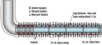 |
| Fig. 3. Anchor hanger and perf spacing for the refrac of Well #1. |
|
Placing a frac plug above the previous anchor hanger, and within the 500-ft interval of interest, would expose this portion of the refrac liner between the frac plug and the previous anchor hanger to a collapse condition. Sufficient expandable liner was used, such that the end of the post-expanded liner was 100 to 200 ft above the upper-most perforation cluster.
INSTALLATION PROCESS
Engineering provided the specifications of the pre- and post-expanded liner (Table 1), as well as the elastomer specifications. Also calculated were the expected torque and drag requirements to avoid buckling and lock-up while running in the refrac liner. Such a calculation was modeled using a 27/8-in. workstring connected to the 4¼-in. refrac liner, with well survey information for a range of friction factors from 0.2 to 0.3. The elastomer-clad refrac liner, with its inner string, was modeled as a composite string. To avoid buckling, it was necessary to use drill collars in the workstring. Figure 4 shows that buckling is observed at roughly 9,600 ft, with a friction coefficient of 0.3. However, it was believed that a conservative estimate of the actual friction factor was 0.25, considering the values for typical muds used.
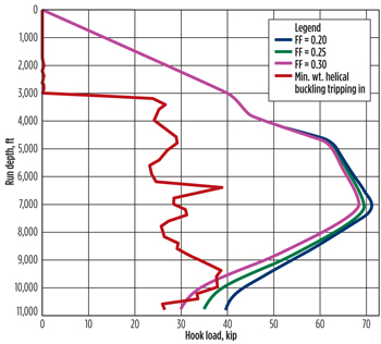 |
| Fig. 4. Torque and drag analysis, showing the impact of friction coefficient on hookload when running the refrac liner assembly downhole. |
|
A second analysis was performed to understand a safe overpull margin during the expansion. This analysis considered the refrac liner as stationary, while the inner string is pulled from the bottom. While pulling out using a 0.25 friction coefficient, the overpull margin between the actual hookload and 80% of yield was calculated as 120 kips. With the anticipated pipe body expansion force of 57 kips, this would imply adequate overpull to expand the pipe.
Another engineering concern was the availability of technology to provide sufficient perforating of the refrac liner and the 5½-in., 17-ppf casing, as well as the availability of composite frac plugs that could be run and set in the refrac liner. Commercially available perforating guns and frac plugs were identified that could perform in the expanded 4¼-in. refrac liner.
Before installation began, all string components were drifted with their standard drift for the innerstring and for the 27/8-in. tubing workstring. The wellbore was circulated until clean, and then drifted to the setting depth, using a special BHA with milling capability to ensure passage of the refrac liner and launcher. Water with calcium carbonate, lost circulation material (LCM) and liquid polymer helped plug off old perforations, so that circulation could be established on the clean out run. Viscous sweeps were circulated to ensure removal of any debris from the cleaning, until returns were clean. Then the well fluid was treated with a lubricant to enable low-friction running of the refrac liner into the horizontal section.
The first step of the installation was to run the launcher, made up to the lower anchor hanger into the wellhead. In this installation, liner was run using special handling equipment to avoid damaging the liner. The 0.06-in. connection sleeves were added over the connection pins of the liners, and the liner joints were made up to the specified torque for this refrac liner. The roughly 3,200 ft of the liner and anchor hangers were made up to the lower anchor hanger and held in the slips.
With the liner run into the wellhead, the casing tools were rigged down, and the innerstring running tools were rigged up. The inner string was then run into the refrac liner comprising an upper safety sub, followed by the joints of tubing and several joints with debris-catching devices. The inner string was tagged on the lower safety sub on the expansion cone assembly and rotated to screw into it. The liner was filled with clean, lubricated water. After the inner string was made up, the inner string tools were rigged down. A tapered guide was threaded unto the top of the upper anchor hanger to facilitate running of tools. The refrac liner assembly was then run down the wellbore using joints of 27/8-in. workstring, connected to the inner string using a crossover, followed by drill collars, and then another crossover.
During running downhole, the liner hung up, 10 stands from the setting depth. It could not be washed down further, although it was broken free, so that its free pickup weight was determined as 130,000 lbf. To force it downhole further, the backside was filled with water, with the 27/8-in. stripper rubber installed, and the refrac liner assembly was pumped down. The setting depth was confirmed by tubing tally.
The last stage of the installation was expansion of the liner. A rig rental pump was found to be sufficient for pumping the expansion. From the pump, 2-in. steel chiksan lines were connected to the workstring, and lines were tested to 5,000 psi. The 2-in. steel lines were used to circulate and land the dart. One tubing capacity was circulated at 2 bpm before pumping the dart to the float to pressure up, and initiating expansion. The dart seated with 2,800 psi, and the tubing was picked up with 130,000 lbf on the weight indicator. The rig pump was pressured up to 5,000 psi to initiate expansion at a rate of 0.5 bpm, and an expansion rate of 28 ft/min. Expansion of the first anchor hanger (with elastomers) was continued until completed and the refrac liner anchored in the base casing, as determined by putting on 20,000 lbf, overpull. Expansion was completed, making 50 full pulls to expand the liner racking back doubles with the aid of a drill pipe circulation (DPC) tool. Average expansion pressure was 3,000 psi, with 20,000 lbf, overpull. The liner was pressure-tested to 4,500 psi for five minutes before bleeding off. The float shoe in the nose assembly of the launcher at the end of liner was not drilled out.
The installation procedure went as planned, except for getting hung up short of the setting depth when running the refrac liner. In future refracs a special lubricant was added to the wellbore fluid that allowed running of the refrac liner to the setting depth with no problems.
PRODUCTION RESULTS
There is limited information regarding the details of the refrac of Well #1, except as was mentioned previously. It is known, however, that two offset wells on the same pad as Well #1, referred to here as Well #2 and Well #3, were also refractured at approximately the same time, using other methods of perforation diversion. The monthly production data for these three wells are public information, and the gas production is plotted in Fig. 5. Well #1 with the refrac liner shows post-refrac gas production as good as, or better than, those for the two offset wells. Public information on these wells also indicates that the original fracturing treatments for these three wells were similar, as shown in Table 2, and that the layout of these wells can be approximated, as in Fig. 6.
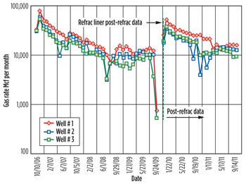 |
| Fig. 5. Gas production history, pre- and post-refrac, for Wells #1, #2 and #3. |
|
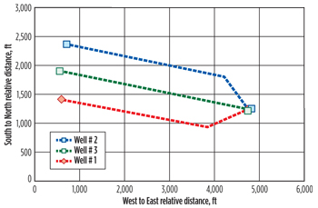 |
| Fig. 6. Approximate relative positions of Barnett Wells #1, #2 and #3. |
|
| Table 2. Initial fracturing treatment information for Wells #1, #2 and #3. |
|

|
Figure 5 indicates that gas production for Well #1 with the refrac liner was better than that for the other two wells, for both the initial frac and the refrac treatment. The post-refrac production of Well #1 exceeds that for Wells #2 and #3 by more than 161 MMcf over the 23-month, post-refrac period shown in Fig. 5. Table 3 gives the cumulative post-refrac production for each well, and shows that the ratio of the production for Well #1 to offset Wells #2 and #3 is 1.53 and 1.39, respectively. Water production was variable and no definitive trends could be identified.
| Table 3. Ratio of Well #1 parameters to offset Wells #2 and #3 parameters. |
|

|
As shown in Table 3, any factors can contribute to this difference in production, including interval lengths and fracturing material parameters. It can be seen that the ratios of interval length, alone, cannot explain the difference in production. When comparing Well #1 with Well #3, it can be seen that the ratio of amounts of frac fluid and proppant used could explain the difference, but this does not hold true when Well #1 is compared with Well #2. Of course, the increase in production for Well#1 versus its two offsets could be an additive effect of all the variables. But, there are other factors that can also come into play, in addition to the fracturing parameters and the type of refrac diversion method. One is the location of the well. Figure 6 shows that Well #3 was positioned between Well #1 and Well #2, and could be impacted by hydraulic fracture overlap. Also, depending on the position of neighboring wells, the production for Wells #2 and #1 could also be impacted.
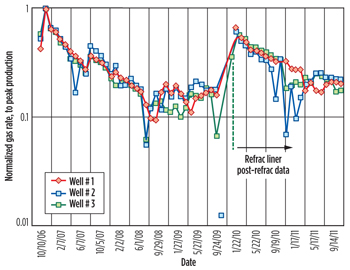
To account for the various factors that can affect the post refrac production, the production data in Fig. 5 were normalized to their initial peak post-frac production. In this way, it can be seen how the refrac performed relative to its initial frac, and, thus, one can judge the effectiveness of the refrac and can compare it with the effectiveness of the refracs of the other wells. Figure 7 shows the monthly production, normalized to the peak initial post-frac production for each of three wells. They are surprisingly similar. The peak normalized production for the three wells after the refrac ranges from 60% to 70%, with Well #1 having a peak normalized refrac production of 66%, and Well #3 having the highest at 70%.
 |
| Fig. 7. Normalized gas production data for Wells #1, #2 and #3. |
|
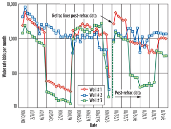
Second case history. For the second case history, another Barnett refrac was done on a different pad (Well B) using the 4½-in. expandable liner in 5½-in., 17-lb/ft casing for perforation diversion. Another well on the same pad (Well C) was refractured at nearly the same time, using a different method of refrac diversion. Learnings from the first refrac (Well #1) were utilized when installing the refrac liner in Well B that facilitated the installation, most notably using the appropriate lubricant in the well fluid while running the roughly 3,400 ft of refrac liner. This lubricant was also used in the successful installation of roughly 4,300 ft of 4½-in. expandable liner in a lateral, with 5½-in., 20-lb/ft casing in the Marcellus shale.
 |
| Fig. 8. Gas and water production rate histories, pre- and post-refrac, for Wells B and C. |
|
The production performance of Wells B and C is shown in Fig. 8. The gas production rates for Well B with the refrac liner become greater after about one year of production. The total post-refrac gas production for these wells are 465,274 Mcf versus 373,415 Mcf for Wells B and C, respectively. Also, the post-refrac water rates are substantially greater than the initial water production rates, which may mean that these wells have fractured into water below (e.g. into the Ellenburger formation).
CONCLUSIONS
This study has shown that a solid-steel expandable liner with suitably positioned anchor hanger seals is a viable method for isolating perforations, to ensure that staged fracturing proceeds as desired. The liner can be run to the desired setting depth in long laterals, expanded downhole to achieve frac-stage/perforation isolation and to maximize liner ID, and perforated between old perforation clusters to stimulate new rock to maximize reserves.
The two case histories presented here indicate that production results using the expandable refrac liner give comparable, or better, gas production than other methods of perforation isolation, such as squeezing off the old perforations or diversion of flow from the old perforations using diverting agents. The results of the two sets of data show that initial water production following the refrac may be increased when using the refrac liner, which would be desirable to get the frac-fluid load back. However, continued water production is not conducive to production.
For these case histories, it is believed that individual perforation cluster isolation within each frac stage was not that necessary because of the small annular clearances between the base casing and expanded liner. Important steps for successfully running the liner were to circulate LCM to reduce flow into the old perforations, to achieve good circulation for cleaning the wellbore, and to use suitable lubricants in the wellbore fluid to reduce drag. Torque and drag analyses for the liner and workstring are also required to determine the need for drill collars near the liner top to avoid buckling.
The main advantage of the refrac liner in these case studies was in giving the operator assurance as to refracturing a given planned frac stage. Once this refrac liner is installed, the subsequent frac treatment can proceed more easily with less real-time diagnostic expenses and interruptions into the fracturing treatment to make downhole adjustments to help achieve the desired injection objectives. 
REFERENCES
1. Allison, D., S. Curry and B. Todd, “Restimulation of wells using biodegradable particulates as temporary diverting agents,” CSUG/SPE paper 149221-MS-P, Canadian Unconventional Resource Conference, Calgary, Canada, Nov. 15-17, 2011.
2. Vincent, M. C., “restimulation of unconventional reservoirs: When are refracs beneficial?,” SPE paper 136757, Canadian Unconventional Resources and International Petroleum Conference, Alberta, Canada, Oct. 19-21, 2010.
3. Durst, D., and J. Fritsch, “And the list goes on, expandable technology helps operators get more out of their wells at a time when higher productivity is number one on the priority list,” E&P, November 2009.
4. “Review of emerging resources: U.S. shale gas and shale oil plays,” prepared by INTEK for the U.S. Energy Information Administration (EIA), July 2011.
5. Kuuskraa, V. A., Gas Shale Development Workshop, Beijing, China, April 2010.
6. Bruner, K. R., and R. Smosna, “A comparative study of the Mississippian Barnett shale, Fort Worth basin; and Devonian Marcellus shale, Appalachian basin,” DOE/NETL Report 2011/1478, April 2011.
7. Shekhar, S., and H. Ramakrishnan, “A novel screening method for selection of horizontal refracturing candidates in shale gas reservoirs,” SPE paper 144032, SPE North American Unconventional Gas Conference and Exhibition, The Woodlands, Texas, June 14-16, 2011.
8. King, G.E., “Thirty years of gas shale fracturing: What have we learned?,” SPE paper 133456, SPE Annual Technical Conference and Exhibition, Florence, Italy, Sept. 19-22, 2010.
9. Langley, D., “Oil country tubular goods, next steps for expandables,” World Oil, July 2010.
|
The author
JOHN CAMERON is the Well Services Solutions manager at Enventure Global Technology in Houston, where he has worked for nearly two years. Before coming to Enventure, Mr. Cameron worked as a consultant with Eclipse Petroleum Technology in Houston, and as a consultant for PCM Technical in Tulsa, Okla. Before his role as a consultant, he worked as a staff engineer for 18 years at Amoco Production Technology Center in Tulsa. He received his PhD and MS degrees in chemical engineering from the University of Michigan and The Ohio State University, respectively, and a BS degree in mathematics from The Ohio State University. He is a registered PE in Oklahoma. |
|
OCTG Technology Center optimizes connection performance in solid expandable liners
Field results show that solid expandable liners improve well architecture, reduce operational costs, mitigate drilling hazards and, in some cases, make previously undrillable wells drillable. However, radial expansion of the liner places severe combinations of bending, tension, compression and pressure on the threaded connections. If a connection fails during downhole expansion, the operation cannot be completed, and substantial additional intervention costs could be incurred. Therefore, connections with special features are required.
To optimize performance of solid expandable liners, Weatherford is engineering specialized threaded connections at its dedicated Oil Country Tubular Goods (OCTG) Technology Center. These fit-for-purpose connections are designed, tested and qualified based on API and ISO guidelines.
The latest development from this arena is WTXC threaded connections, designed to handle the rigors of solid expandable liners with larger ODs, commonly used in openhole and offshore applications. The WTXC is, therefore, designed with multiple seals and a higher thread count, to provide additional strength and sealing capability, ensuring more dependable pressure integrity in these critical applications, both during and after expansion. The first WTXC connection to be introduced, sized for 95/8-in. expandable liners, has successfully met all testing qualification requirements and is undergoing field trials.
Essentially, when a liner is expanded downhole, a new product is being manufactured, remotely, down the wellbore. Without exception, the product has to perform exactly as designed, so proper testing is critical to the success of solid expandable liner connections.
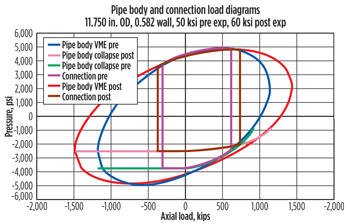
Recognizing that solid expandable liner connections need to be held to the same performance expectations as premium, nonexpandable connections, the company built the OCTG Technology Center, a 20,000-sq-ft testing facility in Huntsville, Texas. Here, rigorous qualification tests, designed to reflect realistic well conditions before, during and after expansion—and thus meet API RP 5-EX criteria—verify the unexpanded and expanded connections’ tri-axial performance envelopes, Fig. 1. In addition, customized tests can be performed for clients with special application requirements, for connections with ODs up to 16 in.
 |
| Fig. 1. By maintaining compression and tension loads during expansion in the testing phase, Weatherford is able to reproduce all conditions experienced downhole, meeting API RP 5-EX testing requirements. |
|
On premises is an array of specialized laboratories and equipment, including a custom-built, dynamic-load expansion simulator, as well as a unique bending frame that enables researchers to study the effects of wellbore deviation on connections.
The first connections designed and tested at the facility were FODC-OR threaded connections, which are used for smaller-diameter liners. Two unique features enhance sealing capacity and help to effectively contain internal and external pressure: a single O-ring seal, and an engager ridge on the ID. With a two-step thread design, this connection can accommodate a single O-ring seal in the middle, as opposed to requiring one on each end of the connection. The patented engager ridge activates during expansion to amplify O-ring compression, further enhancing sealing capacity. To date, more than 200 FODC-OR expansion installations have been performed, in both cased and openhole applications.
With the introduction of these new threaded connections, specially designed to handle the considerable stresses to which solid expandable liners are subjected, operators are experiencing significant improvements in downhole performance and reliability. 
|
|


