MUSTAFA R. AL-ZAID, MOHAMMED S. AL-GHAZAL, FADEL AL-GHURAIRI, and SAAD M. AL-DRIWEESH, Saudi Aramco; JOSE VIELMA, ALEJANDRO CHACON and JOSE NOGUERA, Halliburton
Coiled tubing (CT), acid stimulation interventions in openhole, multilateral wells represent one of the industry’s most challenging scenarios. Factors, such as a corrosion, CT limitations, steering tool assemblies and fluid placement, all require innovative solutions to maximize well productivity.
In recent years, the number of openhole, multilateral wells drilled in Saudi Arabia has increased significantly. Consequently, this initiative has also increased the requirements for performing acid stimulations, and for enhancing well productivity. A solution to this problem needs to address the corrosion challenges associated with pumping high acid concentrations, in sour and high-temperature environments; reaching target depths, in multiple laterals, with complex well architectures; the use of effective steering tool assemblies to access multiple laterals; and the placement of acid stimulation fluid systems in target zones, across the open holes, to maximize well productivity. This article documents the engineering solutions developed to address these specific challenges.
WELL ARCHITECTURE
Well architecture is key in determining the type and size of CT and downhole tools to be used during well interventions. It is also important for defining the stimulation strategy (especially in multilateral openhole completions), as well as for evaluating whether CT can reach the targeted depth, in extended-reach horizontal wells. The multilateral, HPHT, sour gas-producing wells drilled in Ghawar field are generally completed as per the configuration shown in Fig. 1.
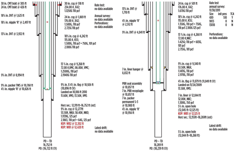 |
| Fig. 1. Typical diagrams of multilateral, gas-producing wells in Ghawar field. |
|
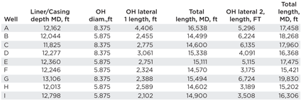
These two completions vary in casing size used and setting depth, utilizing 4½ in. to 13½ lb/ft tubing in all cases, with a minimum restriction of 3.688 in. (R-nipples). Openhole lateral diameters also vary from 5⅞ in. to 8⅜ in., depending on the internal diameter of the last casing (6.094 in. for 7 in.-liner and 8.535 in. for 9⅝-in. casing). The angular build-rate starts from 9,000 ft to 10,000 ft MD, with a maximum dogleg kept under 10°/100 ft; a maximum inclination of ~90° is reached, approximately 500 ft below the deepest casing shoe MD (although in some cases, the maximum inclination is located above the production liner/casing shoe). Figure 2 shows a lateral deviation and azimuth. TVDs vary from 11,500 ft to 13,000 ft. The number of laterals drilled may also vary, and in some wells, two openhole laterals are drilled, but in some other cases, as many as three laterals are drilled (although only two laterals are treated). Table 1 shows a summary of treated openhole section lengths during the CT stimulation campaign.
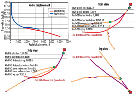 |
| Fig. 2. An example of multilateral, gas well construction. |
|
| Table 1. Openhole section lengths. |
|
|
FORMATION DESCRIPTION
Wells described in this paper were completed as multilateral, openhole completions, leveraging on the Khuff consolidated carbonate formations. The minerology of the targeted zones is mainly calcite, with strakes of dolomite. Other important reservoir parameters are:
- Reservoir pressures ranging from 4,500 psi to 6,500 psi.
- Target depth TVDs from 11,500 ft to 13,000 ft.
- Formation permeability averaging at 0.2 MD.
- Bottomhole temperatures (BHTs) ranging from 250°F to 300°F.
- Formation fluids: gas condensate of 40° to 45° API; condensate gas ratio from 50 bbl/MMscfd to 150 bbl/MMscfd.
- H2S concentration varies from 1% to 10%, and CO2 concentration from 1% to 4%.
- Net pay defined as per zones with a porosity >5%. Net pay length average is around 50% of total lateral length.
MULTILATERAL WELL INTERVENTION CHALLENGES
Dual-lateral, openhole configurations, when combined with extended reach and corrosion issues, carry with them complex challenges. In this case study, detailed analysis and pre-job engineering work were carried out to develop the best technical solution, without compromising the overall goal of being able to stimulate all the desired zones. Therefore, besides being able to reach further along an openhole section, it was necessary to combine a set of tools that can aid in identifying and steering the BHA into an alternate lateral, maintaining the option of placing the fluid with the hydrajetting tool, for precise fluid placement. This section documents the solutions developed to tackle these challenges.
Challenge #1—Corrosion concerns in acidic fluids and sour environments. When dealing with extreme acidic fluid systems, such as 26% hydrochloric (HCl) acid, in hot wells producing up to 100,000 ppm of H2S and 3% CO2, tubular and CT string corrosion mitigation and prevention, become of paramount importance and quite challenging tasks. Corrosion is one factor that dramatically affects CT string-life, as well as downhole tools/equipment integrity. Among important factors to evaluate, when working in acidic and sour environments, are:
- CT steel properties (CT grade, hardness, weld type)
- CT string management such as: Accumulated fatigue, accumulated acid exposure, ovality, pitting, wall thickness losses, cracks, etc.
- Connector and downhole tool material selection
- Elastomer selection
- BHT and bottomhole pressure (BHP)
- Exposure time to acidic and sour environments.
- Concentration of sour gases
- Stimulation acid type and concentration.
Hydrocarbons containing acidic gases, such as, H2S and/or CO2, can be corrosive to CT, due to pH reduction, as described by Hampson et al.1 Low-pH, aqueous fluids, when subject to high temperature, accelerate corrosion by providing a plentiful supply of hydrogen ions. Any brine in the production fluid will also increase the overall corrosiveness to the CT, as well as provide an aqueous medium for contamination. In other words, aqueous fluids become very corrosive in the presence of H2S and CO2 gasses, inducing sulfide stress cracking (SSC) on tubulars. Use of highly-concentrated, inorganic acids (i.e., 26% HCl) for carbonate dissolution further intensifies tubular corrosion concerns, so the appropriate, tested selection of corrosion inhibitors and intensifiers is important under these conditions.
During this CT stimulation campaign of multilateral, openhole, HPHT, sour gas-producing wells at Ghawar field, many actions have been taken to minimize or mitigate corrosion issues on completion and CT strings. Among these, the following measures taken both in the lab and on the field:
Loading the well with treated water, prior to running CT in hole. This has been done mainly to reduce wellhead pressure and/or kill the well, so H2S migration is minimized. The treated water is prepared by mixing fresh water with 0.2 vol% non-emulsifying surfactant, 5% mutual solvent, and 0.2 vol% of SSC inhibitor, which is a sulfur anti-cracking agent and forms a protective film on the pipe.
Circulating treated water loaded with SSC inhibitor while traversing the openhole section. The same treated water blend is circulated to keep the outside of the CT string coated at all times, with the SSC inhibitor, when running CT in hole.
Extensive corrosion tests on CT and completion material coupons. Laboratory corrosion evaluation was performed, utilizing QT-900 and N80 coupons, with 26% HCl and 15% HCl, in sweet conditions, as well as in 2% H2S sour conditions, for at least 6 hr. of contact time, and at a maximum temperature of 275°F. During the corrosion-rate evaluation, several corrosion inhibitors, corrosion inhibitor intensifiers and sulfide, anti-cracking, acid-soluble agents were tested at different concentrations, until the desired corrosion rate was below the 0.05 lbm/ft2 threshold. As stated by Nasr-El-Din et al.,2 When using CT strings, where the thinner wall thickness is in front of the producing zone and subject to more frequent exposure to corrosive environments, there is a more stringent weight loss limit of less than 0.02 lbm/ft2.
Using a non-acidic, solids-free diverter, to minimize fluid losses from thief zones. The use of in situ, viscosity-controlled acid, such as systems loaded with viscoelastic surfactants and/or cross-linked gelling agents, depends heavily on formation rock reactivity properties. If the formation shows low reaction rates when coming in contact with acid, the aforementioned type of diverter will increase CT exposure time to live acid. Thief zones can be located in any section of the open hole to be treated, as well as in alternate laterals. Thus, there is a need for effective diverting agents in these operations, to aid in a uniform acid distribution along the zone of interest. The use of associative polymers as a diverting agent, in matrix acidizing and acid fracturing operations, has been described by Nunez, et al.,3 and Solares, et al.4
Minimizing CT exposure to sour and acidic fluid influx. After each lateral is stimulated, and the CT is pulled out to surface, the well is flowed back to production. This is done to minimize CT exposure to partially-spent acid and/or acidic aqueous fluids. If the well is not able to flow, then CT is run in-hole (RIH) to lift the well with nitrogen circulating treated water pills, loaded with SSC inhibitor, at a 0.2 vol% concentration.
Loading acid systems with H2S scavenger. An Aldehyde blend that acts as a sulfide scavenger and cracking inhibitor is added on the fly to all acid blends. A concentration of 1.5%, volume, is being used for anti-cracking purposes, as well as for H2S scavenging. Scavenging H2S from the wellbore completely is often not practical, so the concentration is usually based on lab tests that showed a decrease in general corrosion. For instance, with higher levels of H2S, this inhibitor would not be expected to scavenge all of the sour gas, but it would reduce the corrosion significantly (Hampson, et al).5
Mixing acid blends before reaching targeted zones. To reduce CT exposure time to acidic and sour conditions, as well as save operational time, the required volume of acid and non-acid blends is mixed prior to RIH. Once the targeted depths are reached by the CT nozzles, the stimulation job can start immediately. If access to the openhole sections is not possible, and the targeted depths cannot be achieved by any means, the mixed acid is pumped by bullheading as a contingency plan.
Reaction rates and formation type also play a part. Low reaction rates mean that the CT string will be in contact for longer periods of time with high-acid-strength concentrated fluids. In contrast, the presence of sulfide-based scales may induce the release of an important amount of H2S, when it comes into contact with the acid blends. During these CT stimulation operations, obstructions in the horizontal, openhole section were detected, requiring its removal by mechanical means. In these cases, a high-frequency, fluidic oscillation jetting tool was utilized to bite and penetrate the fill, pumping viscous gel pills assisted with N2 to lift the solids back to surface. Whenever no cleanout progress was observed with mechanical means, HCl pills were spotted to attempt fill dissolution. Sometimes, this was used as a last resort measure, given the possibility of having FeS scale deposition, which would react with the HCl and generate H2S, making it a matter of concern.
Challenge #2—CT lockup in the openhole section. Performing CT interventions, and more specifically, acid stimulations, in an extended-reach scenario, represents a significant challenge in terms of being able to reach the target depths. The wells on this study case are completed with 4.5 in.,13½ lb tubing sections, with a short section of exposed 7-in., 32 lb liner and coming out to a 5.875-in. or 6.125-in., openhole section.
This well configuration poses a problem when it comes to pipe buckling due to two main factors. One is the fact that the openhole section has a higher friction coefficient, which can be over 20% of the friction experienced in a cased-hole section. A second issue is that larger-diameter liners and openhole sections make the CT more prone to buckling, due to the larger radial clearance between the CT and the tubular/open hole.
This larger radial clearance permits a larger pitch angle of the CT, when spiraling or buckling, allowing for more contact points to be developed between the CT and the tubulars/open hole, which, in turn, increases the drag force over this section. More drag force translates into more buckling force, which develops more contact points along the wellbore, which in turn generates more drag, turning the situation into a vicious circle, as per Terry, et al.6 This results in lockup, where the free end no longer travels in the wellbore, and the entire CT, being pushed at surface, spirals into a helix in the vicinity, where the highest wellbore wall-to-CT contact force is experienced.
Initially, these stimulation operations were being carried out with 2-in. outer diameter (OD) CT. As the lockup problem started to occur, and the learning curve steepened, the idea of running larger-OD CT that is able to reach deeper in the horizontal openhole section before requiring the use of friction reducers and/or extended reach tools, was evaluated.
The first approach was to perform the simulations on several intervened and future wells, using both sizes of pipes, and determine the amount of extra depth that the CT could reach by itself. The results were compelling, showing that on most wells, the 2.375-in. CT was able to reach on average, an additional 1,000 ft in comparison to a 2-in. string. The theory behind the additional reach provided by the larger pipe, granted that they have the same tapered wall thickness configuration, is that the larger-OD of the 2.375 in.-CT will have a higher bending stiffness value (E×I, where “E” is the Young’s modulus of the material, and “I’ is the area moment of inertia. See equations below:

This higher bending stiffness value means that the larger pipe is “harder” to bend than the smaller pipe, so having a smaller helix angle (θ) when buckling, allowing for a longer spacing of contact points between the pipe and the wellbore when it begins to spiral. This, in turn, dictates that a higher compressive force is required to buckle the pipe. Although the use of 2⅜ in.-CT will increase the reach, it was not a stand-alone solution to the lockup challenge. The CT simulation also had shown the need for friction-reducer. A viscoelastic surfactant (VES)-based drag friction-reducer was utilized to reduce the friction by an average of 25% between the CT and wellbore. In some cases, where the CT locked up prematurely, and had covered less than 50% of the openhole length, it was decided to spot and circulate the VES-based friction reducer with commingled nitrogen, to reduce the pipe weight, thus reducing the normal force acting between the wellbore and the pipe. In all lockup cases, an additional reach of over 1,500 ft in the openhole section was experienced, enabling the delivery of acid treatment to the deepest zones of interest in the wellbore. Figure 3 illustrates the reduction in the “noise” of the weight indicator reading, which, in turn, indicates that the pipe is gliding smoother along the openhole section of the well.
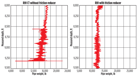 |
| Fig. 3. The effect of friction-reducer on pipe weight is evident in these charts. |
|
Figure 4 shows a well that was stimulated with acid in first-quarter 2012. Three different lockup points were observed, and the friction-reducer pill was circulated to enable extended reach in the horizontal 5.875-in. openhole section. The first lockup point was seen at 15,431 ft, the second one was at 15,574 ft, and the last one was at 17,206 ft. The friction-reducer enabled the CT to reach TD, which was at 17,450 ft, meaning that more than 2,000 ft of additional reach were obtained, with the use of the VES-based system.
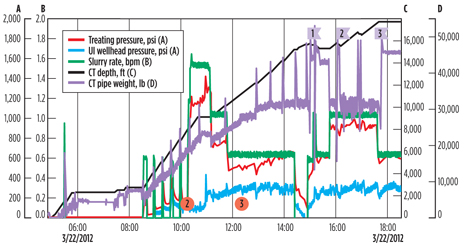 |
| Fig. 4. Friction-reducer used in a horizontal, openhole section. |
|
An additional challenge posed by one of the multilateral wells was that, in one of the laterals, even though friction-reducer was used in the simulations, the CT was still locking up before reaching TD. For this specific well, an additional tool to enable extended reach was considered, in combination with the hydrajetting tool and the steering tools. The extended-reach tool selected was a dynamic excitation tool that works by shutting and opening backflow to the tools below, which, in turn, generates pressure pulses in the CT and BHA that reduce the static friction force coefficient. This enables deeper reach on long horizontal sections, in combination with the VES-based friction-reducer.
Challenge #3—Access to multilaterals. Access to the target-lateral, in a multilateral openhole completion, is perhaps one of the biggest challenges in CT interventions. Despite recent technology developments, the success ratio continues to be below the industry requirements. The set of steering tools used in this case study, has two main components. One is the controlled rotational sub, and the other is the controlled bent sub, which, when used in tandem, are able to identify the kickoff point in the wellbore.
The controlled rotational sub is flow-activated at a set pressure drop, which, in turn, is calculated to be above the circulating flowrate, to be able to RIH while circulating, without having the tool continuously rotating. Once this initial pressure drop is achieved, the toolstring below rotates 30° per cycle. Each cycle will commence only when the rate has been dropped completely, the rate is picked up again, and the set pressure drop has been achieved once more.
The controlled bent sub is installed below the rotational sub, and the activation pressure is set to be above one of the rotational subs to control the activation of each component, separately. Once the rate is picked up, and the set pressure-drop across the tool is achieved, the tool will kick up, always in the same direction, at an angle of 15°, when unrestricted. A 48-in. straight bar is installed between the bent sub and the bottom nozzle, to have the nozzle contact the wellbore. Therefore, the bar has an angle that is shallower than 15°, to have an indication of when the tool identifies the kickoff point. This indication is a drop in circulation pressure seen at surface, whenever the bending sub completes its kick, without mechanical restriction.
The operational sequence then is to RIH ~200 ft below the kickoff point mentioned in the deviation survey, stop the CT and increase the pump rate, so that the rotational sub turns, and the bent sub kicks off. The installed straight bar will make the nozzle rub against the open hole, generating a higher circulation pressure. CT is pulled out of hole (POOH), while maintaining pump-rate stability, with the tools activated, until the bent sub finds the kickoff point seen by the drop in pressure. If the bending sub is still rubbing the wellbore, at around 100 ft above the kickoff point, this means that the tool is pointing elsewhere, and not in the direction of the kickoff point. Therefore, if this happens, the pumps are stopped, CT is RIH once more and the pumps are set online again at the predetermined rate. This allows the rotational tool to gyrate at 30° once more, which changes the direction of the bent sub, to point it in the same direction as the kickoff point. The procedure above is repeated up to 12 times, to achieve full 360° coverage of the wellbore, and helps identify the tie-in point.
Adding to the challenge to steer the CT direction into the target lateral, was the need to make the dynamic diversion tool compatible with the steering tool and, moreover, the need to carry out the stimulation in a single trip per open hole. Tool compatibility was addressed with the design of an isolation sleeve on the dynamic diversion tool, Fig. 5. The sleeve was designed to isolate the injection ports, while steering tools were receiving the flow from the surface, to identify the alternate lateral. Once the sleeve system was developed, the tools were yard-tested, to determine the maximum rates at which the steering tools could operate, enabling circulation while RIH, without compromising the sleeve system isolation, as this would render the steering tools inoperative. Yard tests determined the activation flowrates and pressures, as shown in Table 2.
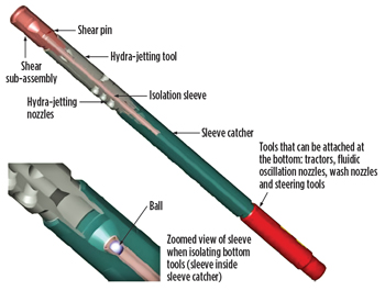 |
| Fig. 5. Placement of a newly designed isolation sleeve system on a dynamic diversion tool. |
|
| Table 2. Yard test results for steering tools and sleeve system. |
|

|
Some cases required a dynamic excitation tool. These cases required a sequencing valve between the steering tools and the excitation tool, to have both systems operate independently. A yard test was performed to determine the compatibility of all tools and their independent operation. The yard tests involved the fettling and fine-tuning of the adjustable nozzles, for the steering tools, as well as the setting at which the sequential valve shut flow to the tools below, to be able to have the dynamic excitation tool work at its optimum frequency, to reduce the static friction coefficient. The yard test yielded the results shown in Table 3.
| Table 3. Yard test results for steering tools and sleeve system. |
|

|
With the yard tests confirming the compatibility of the different sets of tools, it was possible to combine them, and to stimulate both laterals in several wells. This was done without compromising the main goal of the operation, which was to target the best potions of the openhole section, to have the highest increments in gas production. Figure 6 shows the final tool configuration.
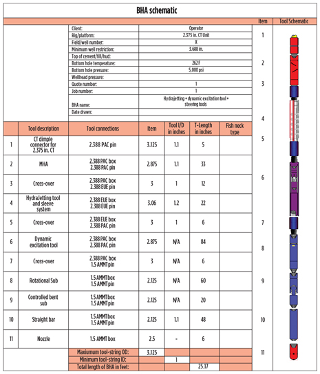 |
| Fig. 6. Specifications for a dynamic diversion tool, a dynamic excitation tool, a sequencing valve and a steering tool assembly. |
|
Challenge #4—Selective placement of acid treatments in openhole completions. One of the most challenging tasks in horizontal, openhole stimulation operations has been to properly enable an operator to selectively place an acid treatment across the zone of interest. These tight carbonate formations require deep acid penetration. The main goal is to generate a combination, or at least to generate a network, of multiple fractures, to etch the surface of existing fractures, and/or to create extensive wormholes.7 The fulfillment of the aforementioned objectives, on long, horizontal, openhole sections becomes a daunting task, as acid can quickly react along the openhole section, generating rock face dissolution on unwanted intervals, instead of generating fractures, or a complex network of wormholes. This previous scenario has an even higher chance of occurring, when the formation is made up mostly of heterogeneous (high contrasts in ϕ and k are found along the wellbore), highly-reactive calcite, with BHTs that frequently exceed 250°F and can go up to 300°F.
Placement of the stimulation fluid in the specific target areas, across the openhole section, was another major challenge. To achieve this, the hydrajet acid injection technique was developed, which takes advantage of the dynamics of fluid moving at very high velocity8, 9 to direct flow to a specific entry point, in front of the nozzle. This dynamic diversion effect generates a low-pressure zone in the CT wellbore annulus, right in front of the hydrajetting tool, which draws fluid from the annulus into the jetted cavity. When the commingled fluids that enter inside the cavity hit the wall of the latter, they transform their high kinetic energy into potential energy, leaving the pressure at the tip of the cavity much higher than at the entrance. This pressure, at the outer boundary (stagnation pressure) of the cavity, can exceed annulus pressure considerably, sometimes rising more than 2,500 psi. This exceeds the fracture pressure at this point, and generates a fracture at the precise point where the nozzle is stationed. Figure 7 gives a graphical representation, of the events that occur within the CT wellbore annulus.
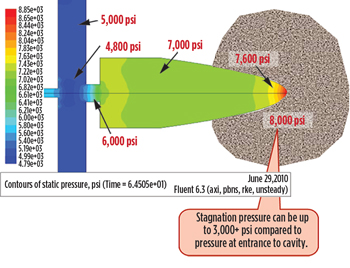 |
| Fig. 7. Examples from laboratory testing of fractures generated by the hydrajetting technique include: a fracture caused by jetting (left); penetration caused by colored ink (center); and a larger fracture (right). |
|
In Fig. 8, the hydrajetting tool was dragged while pumping weak acid at an optimal pressure drop rate, along the carbonate rock sample. The left-hand image shows a fracture that is perpendicular to the direction by which the tool was being pulled. The center image shows how far the fractures extended, and how far the acid was injected into the rock (the trajectory of the tool was perpendicular to the plane where the measuring tape rests). The acid penetrated more than 1 ft, at surface conditions, without the aid of the annulus fluid, boosting the stagnation pressure, to enhance the fracture length. Therefore, bottomhole results are even more compelling.
 |
| Fig. 8. Examples from laboratory testing of fractures generated by the hydrajetting technique include: a fracture caused by jetting (left); penetration caused by colored ink (center); and a larger fracture (right). |
|
To reflect a theory behind the dynamic diversion effect, and the tests run above, a sample pumping schedule was designed for the actual operation. The stages were split up into hydrajet fracturing and hydrajet squeezing sections along the wellbore, as well as combining diversion stages with an associative polymer-based fluid to have an additional measure to control losses to the thief zones. The hydrajet fracturing stages need to be done with the CT in a static position, to be able to increase the pump rate and pressure, to reach the required pressure drop at the nozzle (3,000 psi to 4,000 psi). Acid volumes placed on the hydrajet fracturing stages were usually on the order of 25 bbl to 28 bbl, to reflect an approximate equivalent of 1,050 gal/ft to 1,200 gal/ft.
The depths at which the hydrajet fracturing stages were taking place corresponded to the depths where the openhole logs showed the best porosity and permeability characteristics. This was done to bypass the damage across those gas-bearing zones with the highest production potential. The hydrajet squeeze was limited to additional intervals along the open hole that still had a good permeability and porosity profile, albeit not as substantial as the ones targeted for the fracturing stages. The hydrajet squeeze was usually performed at a rate of 3 bbl/min and 300 cfm of N2, and at a speed of 10 ft/min., which yielded a treatment density of roughly 25 gal of acid/ft.
POST WELL INTERVENTION RESULTS
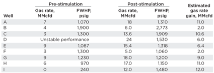
During a period of 36 months, eight multilateral wells were stimulated successfully, in spite of the challenging working conditions. Based on offset wells, with a similar type of completion, the post-stimulation production expectation for each of these wells was between 10 MMcfd and 12 MMcfd. A 70-MMcfd production increase was achieved after finalizing the stimulation campaign, exceeding post-treatment production expectations, Table 4.
| Table 4. Post-CT stimulation production results. |
|
|
CONCLUSIONS
Among the operational lessons learned throughout development of these stimulation interventions, several main conclusions can be drawn:
Openhole, multilateral wells can be effectively stimulated in extremely acidic and sour conditions, without jeopardizing the CT string and well completion integrity.
After analyzing the background pipe buckling theory, it was determined that pumping the friction-reducer while RIH, along the calculated, highest, wall contact force section (from force simulations), yielded additional reach in the lateral. This can be compared with the common practice of circulating the fluid, once the pipe has already buckled.
Kickoff point identification depends mainly on junction and wellbore conditions. Flowback of spent stimulation fluids can deteriorate the geometry of the junction, thereby hindering lateral entry identification.
Likewise, thief zones in the lateral that is not being stimulated can deteriorate the access junction point, minimizing the likelihood of access into this lateral, at a later stage. This is because live acid can swerve into the alternate lateral, dissolving the face of the rock at the kickoff point.
The use of a non-acidic, solids-free diverter to minimize fluid losses to thief zones is critical to minimizing corrosion and maintaining the wellbore and junction conditions for further access into the second lateral.
Determining required operational parameters (pumping pressure and rate) is a key factor while designing the pin configuration for the sleeve on the dynamic diversion tool. Lower-rated pins on the sleeve may shear prematurely, reducing of pumping at optimum clean-out rates, when CT is in the openhole section.
Commingling of nitrogen in the stimulation fluid stream helped to increase delta pressure across the nozzle, and therefore, enhanced treatment penetration. In addition, energizing the stimulation fluid system significantly reduced treatment recovery time. 
This article was adapted from SPE paper 164326.
ACKNOWLEDGEMENTS
The authors wish to thank Saudi Aramco and Halliburton for their permission to publish this article, as well as the field crews involved in performing these successful operations.
REFERENCES
1. Hampson, R., C. Moir and T. Freeney, “Working with coiled tubing in H2S and CO2 wells: A global perspective,” SPE paper 121194, presented at the SPE/ICoTA Coiled Tubing and Well Intervention Conference and Exhibition, The Woodlands, Texas, March 31 – April 1, 2009.
2. Nasr-El-Din, H. and A. Metcalf, “Workovers in sour environments: How do we avoid coiled tubing (CT) failures?” SPE paper 87622, presented at the International Symposium on Oil Field Corrosion, Aberdeen, UK, May 28, 2004.
3. Nunez, W., J. Leal, A. Malik, et al., “Multilayered reservoir stimulation: Case study of effective acid diversion achieved using the associative polymer treatment diverting agent in Khuff carbonate reservoir well in Saudi Arabia’s Ghawar field,” SPE paper 12344, presented at the SPE Asia Pacific Oil and Gas Conference and Exhibition, Jakarta, Indonesia, August 4–6, 2009.
4. Solares, J.R., K. Al-Asiri, C. Franco, et al., “Optimized HPHT acid blends and associative polymer diversion proven to be successful in acid fracturing a multilayered reservoir: a case history from South Ghawar gas fields in Saudi Arabia,” SPE paper 141337, presented at the Production and Operations Symposium, Oklahoma City, Okla., March 27–29, 2011.
5. Hampson, R., C. Moir, T. Freeney, “Working with coiled tubing in H2S and CO2 wells: A global perspective,” SPE paper 121194, presented at the SPE/ICoTA Coiled Tubing and Well Intervention Conference and Exhibition, The Woodlands, Texas, March 31 – April, 2009.
6. Terry, A.R., M. Mahesh, L. Portman, “Modeling coiled tubing drag forces,” SPE paper 89598, presented at the SPE/ICoTA Coiled Tubing Conference held in Houston, Texas, March 23–24, 2004.
7. Rees, M.J., A. Khallad, KA Cheng, et al., 2001. “Successful hydrajet acid squeeze and multifracture acid treatments in horizontal open holes using dynamic diversion process and downhole mixing,” SPE paper 71692, presented at the SPE Annual Technology Conference held in New Orleans, La., September 30, 2001.
8. Eberhard, M., J. Surjaatmadja, E. Peterson, et al., “Precise fracture initiation using dynamic fluid movement allows effective fracture development in deviated wellbores,” SPE paper 62889, presented at the SPE Annual Technical Conference and Exhibition held in Dallas, Texas, October 1–4, 2000.
9. Rees, M.J., A. Khallad, KA Cheng, et al., “Successful hydrajet acid squeeze and multifracture acid treatments in horizontal open holes using dynamic diversion process and downhole mixing,” SPE paper 71692, presented at the SPE Annual Technology Conference held in New Orleans, La., September 30, 2001.
|
The author
MUSTAFA R. AL-ZAID is a gas production engineer with Saudi Aramco’s Southern Area Production Engineering Department (SAPED). He is part of a team responsible for gas production optimization in Ghawar field. Mr. Al-Zaid has designed and executed several critical rig-less well interventions, including wireline, coiled tubing stimulation, and cleaning operations in Saudi Arabia. In 2010, he received his BS degree in petroleum engineering from the University of Adelaide, Adelaide, Australia.
MOHAMMED A. AL-GHAZAL is a production engineer at Saudi Aramco. He is part of a team that is responsible for gas production optimization in the Southern Area gas reserves of Saudi Arabia. In 2011, he assumed the position of gas production HSE advisor in addition to his production engineering duties. In early 2012, Mr. Al-Ghazal went on assignment with the Southern Area Well Completion Operations Department, where he worked as a foreman leading a well completion site in remote areas During 2010, he received his BS degree, with honors, in petroleum engineering from King Fahd University of Petroleum and Minerals, Dhahran, Saudi Arabia.
FADEL A. AL-GHURAIRI is a senior production engineer working on gas fields, in Saudi Arabia. He has 21 of years of experience in production and reservoir engineering. During the last eight years, Mr. Al-Ghurairi has specialized in stimulation and fracturing of deep gas wells. He earned a BS degree in petroleum engineering from King Fahd University of Petroleum and Minerals, Dhahran, Saudi Arabia.
ALEJANDRO CHACON is an account representative for Halliburton Coiled Tubing, in Saudi Arabia. He has held this position since October 2012. Mr. Chacon joined the industry, in early 2006, in Colombia, as a field engineer, and since then, has had assignments with increasing responsibilities. He received his BS degree in mechanical engineering from Universidad de los Andes in 2006. Mr. Chacon focuses on new technology applications and technical sales for CT operations in Saudi Arabia.
SAAD M. AL-DRIWEESH is a general supervisor in the Southern Area Production Engineering Department (SAPED), at Saudi Aramco, where he is involved in gas production engineering, well completion, and fracturing and stimulation activities. Mr. Al-Driweesh chairs several technical sessions in local, regional and international conferences for SPE. He is also the 2013 recipient of the SPE Production and Operations Award for the Middle East, North Africa and India region. He has 26 years of experience in areas related to oil and gas production engineering. He received his BS degree in petroleum engineering from King Fahd University of Petroleum and Minerals, Dhahran, Saudi Arabia.
JOSE R. VIELMA G. is the Halliburton Stimulation and Coiled Tubing Technical Advisor currently supporting ENI Production Optimization Technologies Department in Milan, Italy. Mr. Vielma joined Halliburton in 1991 as a field engineer and has 22 years of experience in the oil and gas industry in several areas, including workover and coiled tubing operations, well control, matrix acidizing, hydraulic fracturing, perforating, sand control, well cementing, water shut-off and production surveillance with operations in Venezuela, Argentina, Mexico, Ecuador, Colombia and Saudi Arabia. He has served as in-house desk engineer for oil companies such as Shell, BP, Pemex, Saudi Aramco and ENI. In 1990, he received his BS degree in civil engineering from Unefa (formerly IUPFAN) in Caracas, Venezuela. He is a member of SPE and has authored several technical papers on field coiled tubing and stimulation technology applications.
JOSE NOGUERA is a country manager for Halliburton Well Intervention, in Saudi Arabia. Mr. Noguera has held this position since November 2011, prior to this position he was a sales manager for Halliburton Well Intervention, in Indonesia. Jose joined the industry early 2001 in Venezuela, as a field engineer. Since then, he has had Hold several technical and managerial position in the Well intervention segment throughout several geographical markets. Mr. Noguera received his BS degree in chemical engineering from Universidad Metropolitana in 2000. He also holds an MBA From IPMI University in Indonesia.
|
|


