Rib-steered motor technology extends CT drilling applications
The rib-steered motor (RSM) is a new directional coiled-tubing drilling system that offers the capability of drilling complex 3D well profiles. Tests in Alaskan fields show that RSM technology has significant advantages over bent-motor drilling.
ADVANCES IN COILED TUBING
Rib-steered motor technology extends CT drilling applicationsThe rib-steered motor is a new directional coiled-tubing drilling system that offers the capability of drilling complex 3D well profiles. Tests in Alaskan fields show that the rib-steered motor technology has significant advantages over bent-motor drilling.OKECHUKWU N. ANYANWU, CHRISTIAN KLOTZ and CARL ULRICH, Baker Hughes
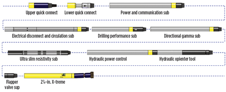
A new directional coiled tubing (CT) drilling steering technology is now commercially available that is based on the concept of closed-loop steerable drilling systems from rotary drilling applications. The new 3-in. rib-steered motor design includes three hydraulically expandable, surface-controlled ribs that generate the required wellbore contact forces that are necessary for drilling complex 3D well profiles. The rib-steered motor platform also offers the capability to drill virtually straight tangents, which is impossible with the combination of bent motors and downhole orientation devices. Testing of this new platform began in 2008 in Alaska and was further improved to become a new standard for horizontal or tangent sections in high-end coiled tubing drilling (CTD) applications. Since then, 3-in. rib-steered motor bottomhole assemblies have drilled more than 23,000 ft in more than 13 wells in Alaska. Rib-steered motor technology improves weight transfer and enables precise control of weight on bit to total depth (TD) for significant extension in lateral section length. It also improves hole quality to make liner running operations more reliable, and reduces the number of required wiper trips. BACKGROUND Traditional coiled tubing drilling (CTD) has employed bent mud motors to create bit rotation that enabled diverging well paths. Since coil rotation was not applicable, an additional downhole orientation device was required for directional control of the motor. For more than a decade, this setup enabled reliable and successful worldwide CTD operations. It also was driven to its limits. Several apparent drawbacks with this platform include unfavorable drag that limits the maximum horizontal reach, suboptimal wellbore quality causing challenges in subsequent liner running operations and the increased distance of inclination measurements from the drill bit. While some of those can be managed to a certain extent, others are intrinsic to bent-motor steering. EARLIER TECHNOLOGY Since the early 1990s, CT drilling thrived on Alaska’s North Slope (Johnson 2003). Operators drilled hundreds of sidetracks to tap reservoir oil bypassed by conventional rotary wells. In the early 2000s, contractors and operators introduced more sophisticated and more capable drilling technologies (Rixse 2002). With those, directional control is achieved using a bent-motor assembly with a hydraulic orientation device. Drawbacks of these designs limited the lateral extent wells could be drilled. Tortuous well paths, suboptimal weight transfer to the bit, excessive drag and non-ideal hole quality were common. In some cases, liner-running operations were adversely affected. CT drilling has improved tremendously throughout the years with development of new technologies and improved procedures. Major drivers and areas of improvement have already been outlined in the literature (McCarty 2001). A typical BHA using conventional bent motor is shown in Fig. 1.
The hydraulic orientation technique used to control tool face direction of the downhole positive displacement motor (PDM) has evolved substantially throughout the years. Formerly, a ratchet-style device was actuated by pulling the BHA off bottom and cycling the mud pumps off. Later technology improvements were capable of making tool face changes while on bottom, drilling with constant pump rates (Venhaus 2006). For operators aiming to maximize horizontal reach of CTD wells and further improving overall project economics, the setup of a bent motor with a downhole hydraulic orienter has limitations:
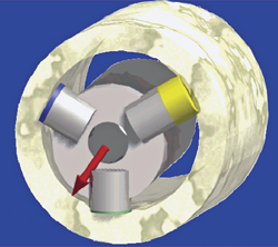
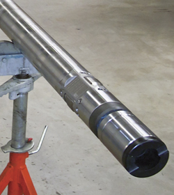
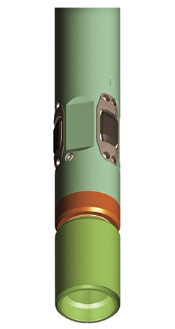
Building upon this improved orienting technology, a new rib-steered motor technology has been introduced that offers a revolutionary approach to CTD, combining a PDM and orientating steering device into a single unit. This provides the capability of steering without the need for a fixed-bend setup. RIB-STEERED MOTOR The challenge to extend CTD applications led to the development of the 3-in. rib-steered motor. This technology achieves the directional objectives with three hydraulically-activated ribs that are closed-loop controlled downhole and can be programmed from the surface by means of downlink. Due to the absence of a fixed bend, the rib-steered motor BHA enables drilling of straight (tangent or horizontal) sections. Since first field-testing, it has evolved into a standard BHA option for CTD. Rib-steered motor application is the preferred option when extending the lateral length is a critical objective and pre-well modeling shows concern for reaching target TD because of low weight on bit (WOB). Its steering concept is based on revolutionary developments made in rotary drilling and transfers these achievements into slimhole CTD technology. Here, rotary steerable systems (RSS) enable complex 3D well paths by individually activating three hydraulically activated ribs that are placed 120° apart from each other in circumference. This has become the de-facto standard for all complex 3D well profiles. A vast amount of literature is available discussing this step-change in rotary drilling, both in terms of technological advancement and economic benefits, and possibilities for operators. An improvement to this technology was made with mud motors above the RSS steering head for increased bit rotation speeds and reduced string rotation, if desired (Rønnau 2005, Kellas 2005, Jaggi 2007, and Anderson 2006). Yet another advancement of this concept for vertical drilling applications was developed afterwards. In it, string rotation is avoided and bit rotation is achieved solely by means of the downhole mud motor without bend (Reich 2003). This 3-in rib-steered motor orientation device is based on this latest development stage as it enables directional control without the need for rotating the string (which is not possible in CTD operations). From top to bottom, the rib-steered motor assembly comprises a near-bit inclination sensor and a bit RPM sensor, an integrated mud-motor power section and a steering section with the three-ribs design known from rotary steerable systems (Figs. 2–5). Within the BHA, the rib-steered motor is positioned between the bit and the power control unit, Fig. 6. This change reduces the length of the steering assembly from 18 ft to 13 ft. .
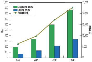
During rib-steered motor technology design, a main engineering challenge was to provide virtually the same steering functionality of an RSS in a substantially smaller tool (4¾-in. was the smallest-size RSS system available as a base for development). This challenge was addressed by optimizing locations of electrical modules and mechanical parts to fit properly into a 3-in. tool assembly. Extensive lab and internal field testing were conducted to ensure the system met the needs of harsh CT drilling. The result provides similar steering modes to those in larger-size rotary platforms. Ribs off mode. In this mode, all three ribs are fully retracted, reducing the outer diameter (OD) to avoid any steering tendency of the tool itself. This mode is used when the tool is run in or out of hole. Inclination hold mode. Steering ribs engage and disengage automatically to maintain current inclination. Steer mode. Based on input parameters for the required steer vector (build and walk force), the internal algorithms will control the three ribs as required to ensure smooth wellbore placement to the well plan and target coordinates. Center mode. In this mode, the rib-steered motor acts as an additional stabilizer. All steering ribs are pressured up equally with a reduced steer force. When the tool is run with E-line coiled tubing, rapid steering control is achieved as downlink commands are received and executed virtually instantaneously. For the design of the steering pads, the engineers benefitted from performance data available from the larger RSS systems. As a result, the pad design is similar to that of larger tools. Such direct translation from large to small was not possible for the steering sleeve itself. In rotary systems, the RSS steering sleeve is a non-rotating device. However, in CTD applications, string rotation is not applicable. Thus, the sleeve design was substantially simplified but with the challenge of a limited diameter. The 3-in. rib-steered motor includes a mud motor power section to drive the bit. It provides a wide operational envelope with a maximum flowrate of 120 gpm and a maximum differential pressure of 1,450 psi. The new directional steering technology is designed in 3-in. size for borehole sizes of 35/8 to 4¾ in. In its current version, the build-up rate (BUR) specification for the 3-in. rib-steered motor BHA is 10°/100 ft. Naturally, actual BUR depends on a wide range of environmental parameters such as rock strength, lithology, formation dip, inclination, rate of penetration, etc. Field tests have demonstrated the system is capable of drilling BURs of more than 14°/100 ft under favorable conditions. However, compared to the BUR limitation of about 40°/100 ft for a bent-motor CTD BHA, the envelope for directional divergence is substantially smaller, confirming the scope of this development is to increase the horizontal step-out in CTD application rather than reduce the time to drill aggressive build sections. During the design phase of the 3-in. rib-steered motor, it was essential that the technology fit seamlessly into the existing CTD drilling BHA and be utilized as an additional system option. The result is fully backward compatible with all existing CTD services, features and measurements. EARLY FIELD TESTING Testing began in July 2008. The primary objective of the first field test was to field-qualify functionalities of the 3-in. rib-steered motor BHA. These included modes such as inclination hold, steer and stabilization. Also tested were rigsite tool handling and testing procedures. Finally, drilling performance—in terms of rate of penetration (ROP), lateral vibration and build-up rate capability—was tested. During early testing stages, difficulties were encountered. Because of its stiffness, the 3-in. rib-steered motor BHA could not exit the standard window milled for conventional tools. In addition, the rib-steered motor performed well when drilling a straight trajectory, but had difficulties in achieving dogleg severities of more than 5°/100 ft. These early issues have all been addressed. The window milling procedure was changed to accommodate tool stiffness, and bit design changes were incorporated to enhance directional control of the BHA. Today, the 3-in. rib-steered motor is reliable and capable of drilling straight well trajectories and doglegs of above 10°/100 ft. In the first test well, the 3-in. rib-steered motor accumulated 20 circulating hours, 11 drilling hours and drilled 1,030 ft (from 9,870 to 10,900 ft MD). An average ROP of 94 ft per hour (fph) was achieved with no noticeable lateral vibration, even during wiper trips. Tool functionality was proven under field conditions and there were no problems with handling the tool at the rigsite. However, a full performance evaluation could not be conducted because the BHA was pulled out of hole prematurely when it could not consistently achieve a required 8° turn to stay on plan. Since then, the 3-in. rib-steered motor technology quickly established itself in Alaskan operations as a new approach to achieve specific CTD well objectives. Today, the 3-in. rib-steered motor BHA is usually the second drilling BHA after window milling is completed. The preferred practice is to pick up the rib-steered motor BHA to drill the lateral section after drilling the build section and landing the well with a conventional bent motor assembly with the hydraulic orienter. The reason is the elevated dogleg severity requirement for the build section of typically 20°/100 ft, or more. This is more than the 10°/100 ft specification for the 3-in. rib-steered motor In May 2011, for the first time in Alaska, a rib-steered motor BHA was used to drill out after milling the window, reducing trip and time required for running a conventional bent-motor BHA. The well was to be placed horizontally with 90° of inclination from the window. The rib-steered motor BHA performed well, drilling 454 ft to 11,699 ft MD. At that depth the bit balled and plugged-up, requiring the BHA to be pulled out of hole. Operators will take advantage of a 3-in. rib-steered motor when there is obvious benefit over running a conventional PDM. The 3-in. rib-steered motor has been run on more than 13 wells since the first field test in 2008. The tool has logged more than 866 circulating hours, 339 drilling hours and drilled 22,676 ft, Fig. 7.
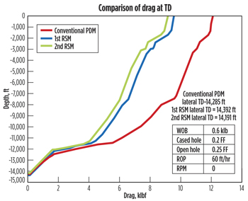
TECHNOLOGY BENEFITS Rib-steered motor technology brings several operational and economic benefits to CTD operators: Near-bit inclination sensors closer to bit. One important measurement provided by the CTD BHA is near-bit inclination (NBI). Knowing the exact downhole depth is critical to CTD operations because, oftentimes, target formations are very thin. Knowing as early as possible the direction in which the drilling assembly is heading from a perspective of depth is important to properly place the well. Thus, it is most beneficial to have the NBI sensor as close to the bit as possible. In the conventional CTD BHA with PDM and hydraulic orienter, the NBI measurement is taken about 16 ft from the bit. With the new 3-in. rib-steered motor BHA and its reduced length and complexity, this distance is reduced by about 30%, or 5 to 6 ft, depending on BHA configuration, thereby enabling more effective and accurate wellbore placement. Geo-steering flexibility to drill desired wellpath (tangents or curves). A typical CTD well on the North Slope is planned for 12°/100 ft dogleg to steer the well into the desired formation. With a conventional CTD steering BHA, a series of left and right turns is used alternately to maintain a particular inclination. This steering “averaging” is avoided with the 3-in. rib-steered motor BHA. Instead, a command is given to the tool from the surface on the target inclination. The system then uses a special “hold inclination” mode to maintain target inclination automatically and so stays in the zone of interest. This functionality ensures inclination is maintained and eliminates undesired turns being forced onto the well path. Thus, the 3-in. rib-steered motor technology provides an unmatched flexibility to drill straight as long as needed and to change inclination and azimuth only when necessary. The technology eliminates the need to trip out of hole to change adjustable kick-off (AKO) setting. Extended CTD lateral reach and reduced wellbore tortuosity/drag. Achieving high lateral departure from the parent wellbore is paramount to maximize reservoir exposure. Oriented or slide drilling results in static friction between the borehole wall and the CT string. The force and weight required to overcome this friction increases as the well’s horizontal displacement increases. This situation is even more aggravated by the traditional sinusoidal well trajectory caused by a bent motor. Hence, reducing the amount of wig-wag in the well path improves hole quality and weight transfer to bit. Typical conventional motor applications set at 1.0 AKO provides between 10° and 12°/100 ft DLS. This leaves the entire well trajectory with this amount of DLS. The capability of the rib-steered motor technology to drill straight when desired, or a very smooth well path, reduces the tortuosity and drag induced into the system. The difference in drag between a well drilled by conventional system (typically at 12°/100 ft feet dogleg) and that drilled by a 3-in. rib-steered motor BHA (at 0 – 4 °/100 ft dogleg) could be as much as 3,000 lb, Fig. 8.
Applying rib-steered motor technology early in the well profile increases the chance of extended stepout from the parent wellbore. Available data from about 92 CTD wells drilled with 3-in. BHAs between July 2008 and July 2011 show that more than 32% of stepouts greater than 2,500 ft were drilled by the 3-in. rib-steered motor platform, while 50% of stepouts greater than 3,000 ft were drilled with this new technology. The record well for Alaska CTD operations, in terms of stepout, was drilled with the new rib-steered motor platform. In May 2011, the system drilled 2,419 ft in a single run, setting a record for the longest single-run distance for a 3-in. BHA. The lateral was drilled to TD of 11,953 ft in 93 circulation hours and 32 drilling hours. This was almost 12% longer than the previous record set by rib-steered motor. WELL 1 CASE STUDY Pre-drilling. Well 1 was planned in 2008 as a single lateral, re-entry to be drilled in Point McIntyre field on Alaska’s North Slope. This was of strategic importance to the development of the western periphery of the field. It was critical to achieve maximum possible footage in measured depth by optimizing wellbore geometry. The sidetrack was to be drilled from a 3.80-in. window exit. During well planning and modeling, it was uncertain whether sufficient WOB would remain at the end of the well to drill this extended reach CTD well to planned TD. Suboptimal reservoir quality was expected in this part of the field, so there was need to maximize lateral reach to increase the chance of contacting good-quality sand. The build-and-turn section was planned for 25°/100 ft DLS. If conditions were favorable, it would have been desired to extend lateral reach beyond planned TD. In that case, use of an agitator was considered an option. Drilling. The build-and-turn section for the first lateral was drilled with a 1.9° AKO bent PDM. Profile length was 637 ft, averaging 21°/100 ft to the landing point. The 3-in. rib-steered motor drilled the 2,049 ft lateral section in one run at average ROP of 92.7 fph to 14,750 ft TD. Average DLS for the lateral section was 4.3°/100 ft. The TD criterion was adjusted because of reservoir quality and the decision was made to drill a second sidetrack off the just completed lateral. The second lateral kicked off at 12,345 ft MD and was initially drilled 255 ft with a conventional PDM to landing point. Average dogleg was 21°/100 ft. Then, a 3-in. rib-steered motor BHA was run, and it drilled the 1,417-ft lateral section in a single run at an average 105 fph to TD of 14,017 ft MD. Project review. The new 3-in. rib-steered motor BHA performed flawlessly, and was successful in several ways:
WELL 2 CASE STUDY Pre-drilling. Well 2 was a tri-lateral re-entry, drilled in Prudhoe Bay field, Alaska, in 2010. The first lateral was drilled using a conventional bent-motor assembly, while the remaining two laterals were drilled with a 3-in. rib-steered motor BHA. The original plan dictated drilling only two laterals from a single-string 3.80-in. window in a 4½-in. production liner. The build-and-turn section for the first leg was planned for 20°/100 ft DLS, while the lateral section was planned for 12°/100 ft DLS. The second lateral was planned to kick-off from the first with a 30°/100 ft BHA. Rib-steered motor technology was planned to be used for both lateral sections to TD. Well planning and modeling predicted the coil would cease to transfer weight to the bit (coil lockup) at about 700 ft from TD for both laterals. A contingency plan was put in place to replace the rib-steered motor with a conventional bent-motor assembly plus agitator. Drilling. The build-and-turn section for the first lateral was drilled with a 2° AKO bend PDM. Profile length was 912 ft, averaging 23°/100 ft to the landing point. The 3-in. rib-steered motor was not available at the time the build section was completed, so the decision was made to continue drilling the lateral with a 0.8° AKO bent conventional PDM. After drilling 697 ft at 87 fph average ROP, the BHA was pulled out of the hole because of insufficient weight transfer and replaced with another bent-motor BHA, including an agitator. This agitator-BHA drilled 1,135 ft to TD of 14,285 ft MD. The 1,832-ft lateral section averaged 10°/100 ft DLS. This lateral was abandoned and re-drilled because the liner could not get to the bottom. The second leg (re-drill of first lateral) was kicked off at about 11,637 ft MD from the abandoned leg. The 589-ft turn section started with a 2° AKO bend and finished with a 2.4° AKO bend, averaging 30°/100 ft DLS. At this point, the 3-in. rib-steered motor tool was available for the following lateral. The BHA drilled the 2,166-ft lateral section in a single run at 83.1 fph average ROP to TD of 14,392 ft MD. An average 4.9°/100 ft DLS was achieved in this lateral. The third leg kicked off at about 11,580 ft MD from the abandoned leg. The 521-ft turn section started with a 2.4° AKO bend and finished with a 2.5° AKO bend, averaging 31°/100 ft DLS. The rib-steered motor was used to drill this third lateral and drilled the 2,090-ft lateral section in a single run at 89.9 fph average ROP to TD of 14,191 ft MD. An averaged 4.7°/100 ft DLS was achieved in this lateral. Project review. Use of the 3-in. rib-steered motor on this well contributed to the success of the project in several ways:
ACKNOWLEDGMENTS LITERATURE CITED |


