|
Drilling with real-time information and control
A second-generation Centurion control system, recently launched by Integrated Drilling Equipment (IDE), will be installed on an IDE 1,500-hp AC Sparta rig, to be delivered to Lewis Energy. The Centurion system employs an “open architecture” software platform, to put real-time information and control in the hands of the drilling contractor, operator and service companies.
Open architecture is a software interface type that allows for adding, swapping and upgrading of controls. Using this type of platform enables service companies to employ specialized applications for control of the auto-driller and pressure control aspects of rigs. The use of customer-supplied applications allows for optimal rate-of-penetration while maintaining zone management, and the safety of personnel and machinery.
The Centurion system does not utilize proprietary networks or software. Consequently, customers may spearhead troubleshooting and the integration of customized features, while still having access to the supplier’s 24-hour technical support. Allowing for a specialization of the software used with the Centurion system means that users do not have to consume valuable time learning another interface. Additionally, information can be accessed on- and off-site via the internet, using a personal computer, Smartphone or Tablet PC.
The Lewis Rig 38 Centurion package will include an IEC satellite system with high-speed broadband; offsite access to all systems; an integrated communication system with VOIP, telephone and talkback; fully integrated IP camera and DVR system; integrated fire and gas detection; real-time logging; Coriolis meters for real-time drilling fluid density, mass flow and temperature and pressure readings; and offsite data collection and reporting. 
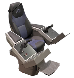 |
| The Centurion drilling control system supports customer-supplied applications. |
|
Engines meet emissions reduction mandate
The new C27 ACERT and C32 ACERT engines from Caterpillar Global Petroleum meet U.S. EPA Tier 4 Final emissions standards, four years ahead of a regulatory mandate. For use by OEMs that manufacture mid-sized equipment for pressure pumping, cementing and well fracturing operations, the engines achieve emission reductions while maintaining reliability and durability.
The two new engines feature technological improvements in key systems to achieve Tier 4 Final status, including a new high-pressure fuel system with refined injection control, next-generation turbochargers, and refined air system management for NOx reduction, an enhanced suite of maintenance-free after-treatment technologies, and advanced electronics and control software. The engines also have been designed to improve fuel efficiency.
OEMs using the engines should be able to reduce their engineering spend by minimizing the number of equipment redesigns required in transitioning from Tier 2 to Tier 4 Final. The engines also lower the overall environmental impact of OEM applications, reducing particulate matter emissions by at least 60% over a Tier 4 Interim model.
With 800-bhp and 1,125-bhp offerings (597 and 839 bkW), the redesigned C27 ACERT and C32 ACERT engines now feature an advanced, high-pressure fuel system that delivers a more complete burn, with less soot and NOx formation while maintaining or reducing BSFC. The turbocharger configuration creates required pressure in the exhaust system to drive the NOx Reduction System (NRS). In addition, this turbocharger results in improved response time vs. Tier 2 configurations. Its minimal moving parts and simple installation requirements improve durability and lower packaging costs. To further reduce emissions, a modular, service-free, diesel oxidation catalyst reduces regulated constituents through an oxidation process.
The after-treatment features a simplified, maintenance-free design that does not require monitoring by the engine control module and allows for a variety of after-treatment installation configurations, creating maximum flexibility when designing and installing the engine/after-treatment on a trailer.
The C27 ACERT Tier 4 Final petroleum engine has been further redesigned with a narrower footprint. With rear-mounted turbos and an option for rear- or front-facing exhaust, this engine allows a side-by-side configuration on a trailer, delivering more horsepower per skid and reducing the number of trucks needed at any particular site. 
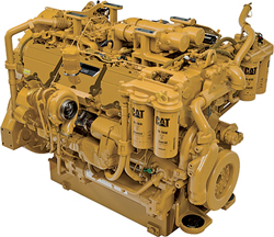 |
| The C27 ACERT engine from Caterpillar has a narrower footprint and may be mounted in a side-by-side configuration on a trailer. |
|
Engineered mousehole allows concurrent operations
Upon client request, KCA Deutag refit its T207 land drilling rig with a 90-ft mousehole, so that drillpipe stands could be built up concurrently with drilling, rather than prior to drilling on the critical path. However, land rig work instructions in Europe state that lifting operations concurrent with pipe rotation are not allowed because of some incidents years ago.
After carrying out a risk assessment and performing necessary engineering, the mousehole was relocated to enable NOV’s Iron Roughneck to reach it properly. A hanging point for one of the tuggers was relocated to keep the tugger line away from well center and over the new mousehole position. IR controls were relocated to ensure that the operator was not on the well center side when operating the IR at the mousehole.
To test whether the operation could be carried out safely, a stand was made up in the mousehole without rotation of the top drive. This was done to determine the best method for the operation and to ensure that crews understood the issues and importance of positioning. The next step was to do the same with rotating pipe at the well’s center, observing that there were, indeed, no issues and at which top drive height the operation could be carried out safely above the drill floor. In the current configuration, a bowl is set over the mousehole, so that pipe joints can be held with hand-slips while being made up. When spinning in the pipe, the upper joint is rotated while carefully ensuring that the elevator holding the joint is free to rotate. On a newbuild rig, an alternative would be to build in a rotating mousehole, so that the upper joint is stationary, and the pipe is spun in with the rotating mousehole, thus even further minimizing the risk of entanglement.
The procedure was thoroughly reviewed and detailed in a new work instruction. The rig has since been performing these concurrent operations, without issue, while saving considerable time. 
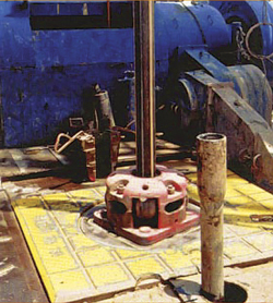 |
| KCA Deutag engineered a 90-ft mousehole to allow concurrent drilling. |
|
Fully autonomous well construction machine
National Oilwell Varco (NOV) has announced plans to deliver a fully autonomous drilling system by 2013. The “well construction machine” will be an interconnected system for constructing wells from beginning to completion. Key to the project is a standard user interface—NOVOS, the NOV Operating System—that is open and available to all developers, which will enable customization of all aspects of well construction.
Today, the human is the loop, according to NOV. For any problem encountered, a human must make a decision on how to proceed. In the future, the human will be in the loop. Decisions will be made by machines, but humans will have veto power, and can regain control at any point. Fact-based decisions will be made by computers, but the knowledge-based decisions will remain human.
Another key component is global accessibility of well information. A tremendous amount of data is gathered, but most of it is not needed by any particular person. It is important to get the right data to the right people at the right time.
NOVOS will drill using a set of data derived from the operator’s well plan, which provides boundaries, set points, instructions and warnings by interval, activity or section, changing the focus from operating equipment to monitoring the well construction process. This significant shift provides new opportunities for a higher level of consistency. NOVOS has a guidance-rich user interface that provides a quick understanding of the status of the well without having to manually correlate and understand the multiple data points necessary today. As a result, better and timelier decisions are made, reducing risk and increasing safety.
During the past two years, up to 150 engineers have worked on development of the rig operating system. The system has been tested with a customer in Norway and on a test rig in Texas. 
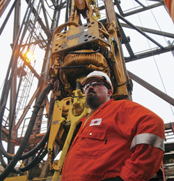 |
| In the Novos autonomous well construction machine, fact-based decisions will be made by computers, but the knowledge-based decisions will remain human. |
|
Closed-loop system for safe, managed pressure drilling
Closed loop drilling (CLD) systems from Weatherford replace a rig’s conventional circulating system—which is open to the atmosphere—with a pressurized system, a technology that provides flexibility when needed. A CLD-ready rig provides the framework to rapidly integrate a range of CLD technologies, such as riser gas handling, advanced flow detection and various methods of managed pressure drilling (MPD).
Closed-loop systems incorporate a few basic components used in conventional drilling scenarios, as well as managed pressure drilling. Most are standard, proven rig equipment and have been available for decades. They include rotating control devices, flow metering technologies, drilling choke manifolds, and downhole isolation valves. Most important is the addition of sophisticated software and controls that integrate these tools as a single system for monitoring, analyzing and managing wellbore pressure.
When these components are paired or used in combination with each other, they greatly escalate the benefits of a closed and pressurized mud return system. Key enabling technologies for a CLD system are a rotating control device, and data-acquisition instrumentation and software.
The CLD process begins by developing a procurement process that reduces costs and the time to acquire and move equipment to location. To further shorten lead times, MPD components and configurations must be clearly specified, and drilling contractors should be willing and ready to deliver ancillary equipment that is compatible with MPD-specific equipment supplied by the service provider.
Standardization of the rig floor is also a requirement for efficient MPD operations. MPD packages require special accommodation, which can be problematic for existing semisubmersibles and drillships. Increased collaboration among all interested parties—the drilling contractor, service company and operator—would minimize costs and lead times, ultimately accelerating the adoption of MPD. To make this a reality, templates for rig modifications must be developed to provide a clear process for implementing an MPD refit. Standards and expertise on the rig floor that ensure the development of MPD-rig designs will provide several tangible benefits for both drilling contractors and operators.
Building MPD capabilities into the rig can significantly shorten the lead-time on equipment and get the drilling operation started sooner. For those wells that are drilling conventionally, but encounter a trouble zone in the reservoir requiring MPD, a rig that is ready to perform MPD can quickly make the transition and continue drilling the well with minimal NPT. The presence of the right MPD equipment on the rig enhances operational safety and allows the operator to make better drilling decisions. The operator will not have to drill through a complex reservoir using conventional techniques. Inability to access an MPD rig may compromise and complicate the drilling process by adding unnecessary risks, safety concerns and potential NPT-related downtime.
If a drilling contractor does not have equipment of the correct size or scope to run MPD, it falls on the service provider to purchase and deploy it. These costs can be large and significantly affect the operator's day rate. A significant operational cost reduction is realized, if the contractor holds this equipment, with the right IDs, and has the space on the rig floor and capability to deploy it subsea at a higher utilization. By transferring the cost of capital from the service provider to the drilling contractor, the operator will see a reduction in the cost of MPD when considering the longer term over which drilling contractors’ assets are depreciated.
The growing number of MPD systems installed aboard deepwater vessels will lead to further improvements in safety and efficiency, as rigs regularly apply MPD to manage wellbore pressures. Time and cost constraints will continue to diminish with increased use and improved processes. 
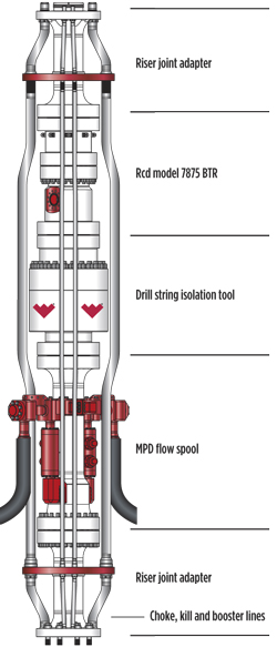 |
| Equipment for a Weatherford CLD system includes a rotating control device, flow metering technologies, drilling choke manifolds, and downhole isolation valves. Sophisticated software controls integrate these tools as a single system for monitoring, analyzing and managing wellbore pressure. |
|
Four-panel shale shaker with 35% higher capacity
Derrick Equipment Company has introduced a technologically advanced Hyperpool four-panel shale shaker, which can be configured in any of three ways: primary shaker, mud cleaner, or as a secondary drier for drilled cuttings.
The new shaker offers up to 35% increased capacity over Derrick’s FLC 503 shaker within the same footprint, while maximizing fluid throughput by the machine’s concave screen bed design. Due to its unique design, the non-blanked open screen area increases capacity up to 115% over conventional shakers, potentially reducing the number of shakers required.
The single-side screen compression system is available in either left- or right-side operation, allowing customization for rig conditions and eliminating the hazard of working between two shakers during screen replacement. The manually operated compression system drives retention pins that force the screen panel downward against the concave screen bed, producing uniform screen-to-deck sealing. The bed cushions are designed to eliminate the need for hardware, are oil-resistant and fully seal the screen panels to the bed, resulting in reduced mud bypass, extended material life and drastically reduced screen panel installation time. Securing screens in this manner, as opposed to a wedge system, increases screen life, improves conveyance and prevents solids from passing under screen panels.
The Hyperpool’s screen compression system reduces screen panel replacement time to as little as 45 sec per panel, permitting complete screen changes in less than four minutes. Hyperpool shakers are equipped with a single-point deck angle adjustment-while-drilling (AWD) feature, which permits the operator to optimize shaker performance without interrupting operations. The AWD allows the screen deck angle to be lowered and raised within a range of +3° to +8°, respectively. The standard power source for the Hyperpool shaker consists of two Derrick Super G vibratory motors, which apply over 8 G’s to the screen frame. The greased-for-life bearing system in these motors eliminates the need for any additional lubrication, thereby reducing maintenance requirements and expensive repair costs.
Additional options for the Hyperpool include a weir feeder (bypass or non-bypass) or a top feeder. The weir feeder permits mud to flow evenly onto the shaker basket for uniform distribution across the shaker screens. Either feeder can be coupled with the Derrick Flo-Divider, which evenly divides the drilling fluid across multiple shakers. The flow divider can be integrated into the Hyperpool installation, where space and flowline elevation are a concern. In addition to single units, the Hyperpool is available in dual and triple combinations on a single skid, configured with an integral flow divider and center cement bypass with a gate valve. 
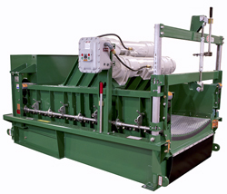 |
| The non-blanked open screen area of the Hyperpool shaker increases capacity by up to 115% over conventional shakers. |
|
Designing a high-performance mud pump
From an initial design standpoint, there are several ways to get more “bang for your buck” out of any given horsepower for a positive displacement mud pump. The intended goal is to maximize performance for a given horsepower range while maintaining minimum equipment weight, superior bearing life and achieving a minimum equipment footprint. There are three primary ways to achieve these goals: longer stroke for a given horsepower, higher mud pump operating speed and adding more pump cylinders.
Designing a longer-stroke pump has several benefits to both the pump and the end-user. Stroking the pump decreases piston rod load, which, in turn, increases bearing life and also increases volume output for a given horsepower range. A standard 1,600-hp pump uses a 12-in. stroke and runs at 120 spm (strokes per minute). Changing the 12-in. stroke to a 14-in. stroke, while lowering the speed to 110 spm lowers the operating piston rod load of the pump by 7%, which effectively increases bearing life by 35%. Along with these longevity increases comes a 16% increase in volume for every revolution of the pump’s crankshaft, along with a 7% increase in maximum volume output, despite running 10 spm slower. ShalePumps’ LLC SP-1614 offers a 14-in. stroke as standard for its 1,600-hp power triplex pump.
A second method of increasing mud pump performance is by increasing the pump’s speed. This can be achieved with a balanced alloy crankshaft and lightened connecting rods. Historically, most mud pumps cannot be over-sped, because they were equipped with cast steel crankshafts (hollow or solid), which are by design, inherently out of balance. This flawed design characteristic, resulting in an off-balance, does not allow the pump to be over-sped. A balanced crankshaft and lightened connecting rods allow for smoother operations at higher speeds. Although API 674 discusses speed limits for equipment, a good rule-of-thumb for pumps is to keep the crosshead velocity under 300 feet per minute (fpm) for any given pump size. A standard 12-in. stroke, 1,600-hp triplex runs at 120 spm, which equates to 240 fpm of crosshead velocity. With the same 12-in. stroke, 1,600-hp pump running at 130 spm, its piston rod load is decreased by 8%, and effective bearing life is increased by 20%. Yet, it only maintains a crosshead velocity of 260 fpm, which is well under API 674 for the given size and pump stroke. Smaller high-performance triplexes are routinely run with a crosshead velocity of 280 fpm in continuous duty applications.
The third method of maximizing mud pump performance is to design it with more than three cylinders. A 1,600-hp quintuplex with an 11-in. stroke would effectively have a piston rod load of half that of a comparative triplex of the same horsepower. This would then allow for a substantial reduction in weight of components without sacrificing output performance. By virtue of its design, a quintuplex also would have substantially reduced discharge pulsation and pressure variations compared to a triplex. With these three design changes, performance is maximized, resulting in a mud pump that is well-equipped to meet the demands of today's high-performance drilling rigs. 
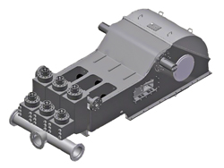 |
| ShalePumps’ LLC SP-1614 mud pump offers a 14-in. stroke as standard for its 1,600-hp power triplex pump. |
|
New make-up/break-out system with high torque
The WR-80 Wrangler Roughneck from Forum Energy Technologies takes on the toughest job on a drilling rig—making up and breaking out drillpipe, drill collars and bottomhole assemblies, and still has more than enough torque to make and break bits. It is pedestal-mounted onto the rig floor and mechanically deployed to either the well center or mousehole, as selected, and is controlled by the machine operator.
The compact tool is hydraulically powered, lightweight and spins up tubulars with high-torque spinning motors. It torques up, and breaks out drillpipe and collars, utilizing an adjustable clamping force feature on the gripping cylinders. By limiting clamping pressure on the gripping cylinders, the potential for “egg-shaping” connections and galling threads is substantially reduced. Its unique design also provides a thread compensation system with 1½-in. of travel while spinning in or out. An optional bit breaker kit is also available.
The WR 80 torque wrench assembly is capable of handling 2⅞- to 10-in. tubulars. Upper and lower bodies, each, have two grip cylinders that take a standard die and holder, which are used through the tool’s range. No additional die holders or other dies are needed for operation. Additionally, an end-of-stroke sensor distinguishes between a completely made-up connection and the end of the wrench stroke.
The lower wrench body does not rotate, and is supported by two level-adjusting arms held up by the positioner arms. The upper wrench assembly sits atop the lower assembly and is connected by a pair of fettered rings. This allows the assembly to be removed for inspection or servicing and allows the upper wrench to rotate above the lower wrench for a total angle of 27°, relative to each other at full make-up or break-out torque.
Proprietary design of the clamp cylinders provides adjustable clamping force to minimize box deflection, and enables the use of a single concave design grip die commonly used in other equipment. The force of the clamp cylinders is adjustable, so that the right amount of force can be applied without “oblonging” the box end of the pipe and reducing the ability to spin and torque the connection.
The torque cylinder is connected between the upper and lower torque bodies. It provides all the force required to make up and break out the connection. Additionally, hydraulic components are designed for simplicity of operation and maintenance. All are mounted to allow servicing and pressure testing through the use of Stauff pressure test ports. 
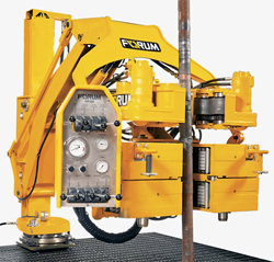 |
| The compact WR-80 is hydraulically powered, lightweight and spins up tubulars with high-torque spinning motors. |
|
Dual-fuel engine cuts costs for land-based drilling
In the oil and gas market, the fuel bill is one of the largest contributors to total operating costs. However, the rapid expansion and abundance of natural gas in some areas of the world is driving a dramatic cost advantage for natural gas over diesel fuel, making natural gas a very economical fuel source for oil and gas operations. For operators of high-horsepower oil and gas equipment, where power density is critical and large quantities of fuel are burned, Cummins dual-fuel technology will provide reductions in total fuel costs by substituting natural gas for diesel fuel in the engine combustion process. The first dual-fuel engine will be the Tier 2 QSK50, rated 1,480 hp at 1,200 rpm. Other QSK Series engines will follow, including engines capable of meeting upcoming U.S. Environmental Protection Agency (EPA) Tier 4 Final emissions regulations.
A dual-fuel engine is based on a traditional diesel engine, with the addition of dual-fuel-specific hardware. When the engine is operating in dual-fuel mode, natural gas is introduced into the intake system. The air-to-natural gas mixture from the intake is drawn into the cylinder, just as it would be in a spark-ignited engine, but with a leaner air-to-fuel ratio. Near the end of the compression stroke, diesel fuel is injected, just as it would be in a traditional diesel engine. The diesel fuel ignites, and the diesel combustion causes the natural gas to burn. A dual-fuel engine can operate either on 100% diesel fuel or the substitution mixture of diesel and natural gas, but it cannot operate on natural gas, alone. Dual-fuel engines deliver the same power density, torque curve and transient response as the base diesel engine.
The QSK50 engine will operate with integrated controls designed to optimize the substitution rate, based on operating conditions, and will seamlessly and automatically transition between diesel fuel and dual-fuel modes. The technology will enable drilling equipment to operate on 100% diesel fuel or in dual-fuel mode, giving the customer flexibility, depending on natural gas availability at the drill site.
A critical parameter for dual-fuel operation is the substitution rate, which is defined as the fraction of the total fuel energy that is provided by the natural gas. Substitution rates vary by load. Maximum substitution rates of 70% can be achieved with the Cummins dual-fuel engine for applications with high load factors. There is also flexibility with the quality of gas that an operator uses. An operator can run on a lower-cost, lower-quality gas at a lower substitution rate, or use higher-quality fuel at a slightly higher cost with a higher substitution rate.
In the United States, dual-fuel engines must meet the applicable compression ignition emissions regulations. While specifics may vary, typically an oxidation catalyst to lower carbon monoxide (CO) and non-methane hydrocarbon (NMHC) emissions is required. This dual-fuel solution will be applicable to new QSK50 engines and as a retrofit on existing QSK50 engines. 
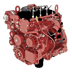 |
| The Cummins QSK50 engine allows maximum natural gas substitution rates of 70%, with high load factors. |
|
|


