KEVIN P. McCOY, PE; and BEN NATHAN, Warren E&P, Inc.
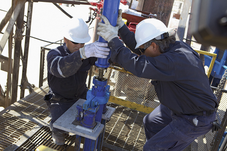 |
| Warren E&P is achieving ESP run times in the range of five to seven years, Photo courtesy of Baker Hughes. |
|
Warren E&P, Inc., is a small, independent oil company with operations in the Wilmington Townlot Unit (WTU) and North Wilmington Unit (NWU), in the city of Wilmington, California. The company actively drills in the Tar, Ranger, Upper Terminal and Ford formations as part of its redevelopment strategy to recover oil from a field that has been in continuous production since 1933.
Ten years ago, average ESP run times ranged from 12 to 18 months. ESPs that ran longer than 12 months were unusual and subjected to forensic analysis to determine why they were able to run so long. Today, average ESP run times are in the range of two to three years, which is considered normal for the industry. Warren is achieving ESP run times in the range of five to seven years, with minimal indications of ESP deterioration, and continues to challenge its vendors to improve on this track record.
Early in the WTU redevelopment, premature ESP equipment failure was the norm, because the chemical compatibility of cable and O-rings with the environment was not properly evaluated during the equipment procurement process. Unsuitable elastomers were initially used in most ESP installations, resulting in initial ESP run times that were sometimes measured in months. Changes in elastomer selections throughout both the pump and cable components solved many of these initial problems. Further improvements in ESP run times were achieved through upgrading to heavy-duty ESPs and better completion practices, which control solids production. Strict installation procedures and continuous chemical treatment have continued to lengthen ESP run times.
TYPICAL SUBSURFACE EQUIPMENT
Warren procures ESPs from two major vendors. Designs and equipment are solicited to best match the anticipated well deliverability and to optimize costs.
When conducting a pump change, anticipated flowrates, fluid composition and operating conditions are usually well known from actual production. Pump designs are selected to optimize lifting the anticipated flowrate from the desired fluid level to the surface. When completing newly drilled wells, there is far greater uncertainty in the anticipated flowrate, fluid composition and fluid behavior.
In new wells, Warren has elected to standardize its designs. Independent of the vendor, Warren uses a mixed-flow stage design, known either as a P18 or a 1750N. The mixed-flow stage designs offer wide pump operating curves that allow for added flexibility to adjust the operating parameters, to best match the resulting well deliverability with desired performance and operational parameters.
Vendors have their own means and methods of accommodating the thrust-loads incurred by operating outside the recommended operating ranges. In all cases, heavy-duty bearing configurations (such as the ARZ or Stabilized Severe Duty designs) are employed as a minimum requirement. Use of these heavy-duty bearings also helps mitigate the detrimental effects of operating ESP stages in upthrust or downthrust conditions, which may result from unanticipated well deliverability or start-up requirements and conditions. The incremental 20%-25% cost incurred over more typical bearings (such as ES or Stabilized Normal Duty designs) is insignificant in comparison to the cost of pulling a failed ESP.
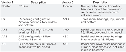
Inside the ESP, bearing and material upgrades stabilize the pump to minimize damage from potential produced solids. These extend the run life but increase the total ESP cost. Table 1 is a summary of the different types of pumps from the two vendors utilized by Warren, tabulated on similar trim levels.
| Table 1. Equivalent ESP types |
|
|
Table 2 is a summary of the approximate costs for the different types of pumps, using the ES/SND pump as the base cost. Costs were for a 117-stage, single-housing equivalent pump design, similar to many that the operator has installed.
| Table 2. Typical cost comparison for a 117-stage or equivalent pump |
|

|
This was not an equivalent comparison, as the example used was for a 117-stage pump, and an XD/SXD equivalent pump would require two housings of 78-stage length.
In a single housing, more stages can be incorporated in a “normal duty” pump because of the minimal number of bearings. To achieve 117 stages in the Extreme Duty/stabilized Extreme Duty pump requires two housings and substantially higher costs. So, the comparison, while valid, requires a totally different design.
Typical surface equipment. Warren uses Cutler Hammer variable-frequency drives, because they are designed as plug-and-play. The drives are installed in custom cabinets that allow for various configurations, such as: a) one drive of 75 hp and three drives of 60 hp; b) four drives of 75 hp; or c) four drives of 60 hp.
Cable feeding both the drive and the transformer meets or exceeds the rating for the installation and demands of four 75-hp drives. The actual cable is VFD-rated and contains additional ground wires. Filters on the secondary side of the drive control harmonics and spikes, which results in increased reliability of ESPs and drives.
This cabinet configuration allows for various types of installations. If a drive fails, it can be replaced, and the well can be placed back in service in approximately two hours. This is not true of other vendor installations, because their drives are component-driven. A typical cabinet installation will contain five-to-six components that will make up one drive. The drives installed by the operator, on the other hand, total four and are contained within one shared cabinet. Replacement consists of removing incoming and outgoing power feeds, and four bolts that hold the drive. Having a spare drive allows for swap-outs and reduces the repair time of the primary drive, minimizing production loss.
Warren has factory-trained individuals, who can quickly diagnose and further reduce down time. The main reason for changing out a unit is to correct cooling issues. This is easily done by removing the covers and cleaning the filter with a brush and low air pressure. Drive failure rates are very low. Only three units out of 120 installed over the course of three years failed, and all of those were repaired and put back in service at minimal cost.
Interchangeability of modular components and rapid replacement reduces down time. This is especially important with fines “fall-back” (fines within the fluid column separating out and falling back through the fluid column) during shutdown that can lock up the top five to 10 stages of the pump, resulting in over-torquing of the shaft and, ultimately, breakage.
Run life. Warren has about 135 ESPs in service at WTU and NWU. After encountering a rash of failures in early 2007, changes were made to various equipment components. Stabilized heavy-duty ESPs with Viton or Atlas O-rings, seals and bags and EPDM cable were run. As the uncertainty of well performance increased with new areas of the field drilled, ARZ/SSD pumps were installed to allow for greater flexibility of gross fluids production ranges.
With the changes made in ESP design, as well as significant improvements in completion and production techniques, the operator has 17 ESPs with run lives between four and five years, and 25 wells with more than five years of operating time, Fig. 1. It is only now that Warren has to pull and replace equipment. Probably half the failures are related to holes in tubing, rather than to ESP problems. The apparent short run times of 45 ESPs are the combined result of the extensive drilling program initiated by Warren in 2011, and the recent failure of ESPs with five or more years of run time.
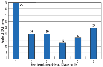 |
| Fig. 1. Pump run-life distribution |
|
ESP vendors usually provide exceptional equipment, but it will only perform, if it is operated as intended. Operating “oversized” equipment at a slower frequency enables the operator to maintain the fluid rates, as equipment wears and loses efficiency. (Note: a larger ESP motor is also potentially required to handle the increased fluids, depending on the loading).
Operating “undersized” equipment at maximum speed may be initially less costly and may be more electrically efficient; but these savings are offset by the replacement expense after a diminished run life. Additionally, increasing the ESP operating frequency increases the fluid velocity inside the pump, which accelerates potential erosion from any produced fines and results in reduced equipment life.
By installing ESPs with ARZ/SSD-type wear-resistant bearings, Warren can operate its ESPs on the “far left” of the pump curve (Fig. 2) and avoid most of the detrimental effects. This condition may occur, 1) if a well does not exhibit anticipated deliverability; or 2) during the slow step-rate start-ups of new wells with certain delicate sand control completions.
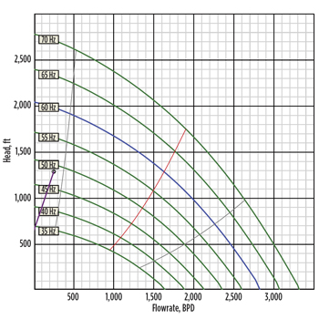 |
| Fig. 2. Running the pump to the left of the curve |
|
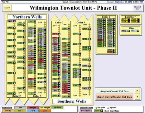
System monitoring. Warren employs a proprietary, supervisory, control-and-data acquisition (SCADA) monitoring package built by a third-party software consultant that uses Elipse software. Every ESP at WTU and NWU is monitored by the SCADA system, Fig. 3. The SCADA software used by the operator has been developed out of operational demands, and continually receives upgrades as user requirements grow. Though initially intended as a tool to monitor ESP performance, this software has now grown into a process control tool.
 |
|
|
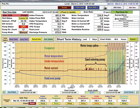
Figure 4 shows a screen output from the Elipse Viewer software. The parameters that are typically monitored include: intake pressure, intake temperature, motor temperature, motor current, frequency of current, and the computed rate of change in intake pressure. The user is able to review the data in fine detail for up to seven days in 2-min. increments (with adjustable time scales), or 90 days in 15-min. increments. On a monthly basis, consolidated data are archived and retained for future use and analysis.
 |
| Fig. 4. SCADA shutting in a well |
|
The SCADA software allows the operator to monitor, in real time, what occurs downhole and to then make the necessary adjustments to ensure longevity of the ESP. Changes to injection within a producing well pattern will change the reservoir pressure and wellbore deliverability. This, in turn, will change the amount of fluid over the pump (and resulting intake pressure). Since Warren typically operates ESPs with only 150 psi at the pump intake (of which 50 to 80 psi is gathering system back pressure), it is important to reduce the pump speed quickly, if inflow is diminished, to prevent pump-off and damage to the ESP.
Digital monitoring of subsurface parameters has enabled automation of ESP operations. For example, early in SCADA system development, Warren chose to limit the ESP motor operating temperature to 310°F. Analyses conducted during teardown of equipment have shown that running equipment beyond this temperature can result in excessive motor wear or deterioration of the oil bath. As a result, the motor temperature parameter was monitored, alarmed and subsequently used to control the ESP automatically. This control has now been extended to monitoring ESP intake pressure and controlling VFD frequency.
The ability to monitor and visualize the data allows operators to properly operate the ESPs and also allows reservoir engineers to directly monitor the changing subsurface pressures. Because the quartz gauge downhole sensors are sufficiently accurate, and the output is consistently recorded, the SCADA software allows the reservoir engineer to monitor buildup well tests (Horner plots) and drawdown well tests, monitor injection response, and review the response to other subsurface operational changes.
Another significant benefit of the SCADA system is that it enables Warren to predict the forensic findings following removal of an ESP from service. This has been confirmed during forensic tear-downs of decommissioned ESPs. These tear-downs have developed a wealth of intellectual knowledge that is employed to further improve operational parameters and ESP run life. This, in turn, enables the operator to refine the design, installation, control and treatment of existing and future ESPs.
Completion recommendations. Generally, ESPs do not handle fines or sand. Production of sand for only a few hours of operation can destroy an ESP pump section, which will necessitate removal of the entire system, followed by refurbishment or replacement. Cleaning the intermediate casing string after running the liner and/or gravel packing the well is just as important as preventing migration (inflow) of sand from the formation.
Warren has experienced four ESP failures due to unconsolidated frac packs. In each case, the failure was caused by not achieving a solid pack-off of one of the intervals, which resulted in the “flow-back” of both formation and resin-coated frac sand. In hindsight, a screen should have been run immediately after the frac to prevent the potential of any future sand inflow (or as an alternative, an over-the-top frac job).
Failure to properly clean the intermediate casing prior to installing an ESP has also caused at least three premature failures. Solely circulating at high rates in horizontal wells may not be sufficient to clean the fines that lay on the bottom. For example, during a pump change in one particular well, the new pump was installed without sufficiently cleaning the liner. The remaining fines and solids then entered the replacement ESP, which promptly failed (Fig. 5) because of excessive wear.
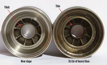 |
| Fig. 5. New P18 stage compared to 36-hr run life with sand (note thinness) |
|
During completion of another well, a new liner productive interval (1,200 ft) design and aggressive intake drawdown resulted in significant sand volumes (up to 10% by volume) entering the ESP. When the ESP stages seized because of sand (Fig. 4), the SCADA system shut down the ESP, when the motor temperature exceeded the pre-set limits. Warren was then able to back-wash and clear the ESP, thereby saving it from failure. Time constraints (i.e. conflicts with the drilling rig) required that the ESP could not be pulled, and the well properly circulated clean. As a result, the equipment was raised 1,250 ft, MD, or 250 ft vertically away from the sand remaining in the intermediate casing, and returned to production. Since the ESP was already potentially damaged, it was left in the well while the liner design was evaluated. The liner evaluation is now complete, and the ESP continues to run to-date as though nothing had happened to it (5 months and counting). This is largely due to the initial overdesign. The operator does not, however, anticipate that this particular equipment will reach the expected five-or-six-year run life. This is a testament to over-designing the equipment and having a good SCADA system monitor it.
Figure 6 compares two pump rotors. One has been subjected to fines production, and one has not. Had the tubing not failed in the well without fines, the pump could have easily run another 12 to 24 months.
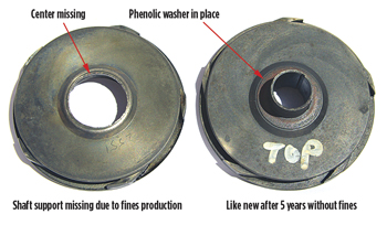 |
| Fig. 6. Two 475N stages—five-year run life, with fines (left), and without (right) |
|
When fines are produced in the fluid, whether from an incomplete gravel pack or a failed liner, the damage can be very severe, Fig. 7.
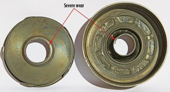 |
| Fig. 7. Stage subjected to fines—compare to Fig. 8 |
|
Wells, in which fines have been substantially eliminated, can be expected to run easily for 60 months, if the equipment is not overloaded, the pump has never been allowed to run dry, and corrosion of tubing and pump parts has been effectively eliminated, Fig. 8.
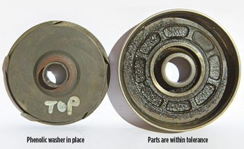 |
| Fig. 8. Five years with no fines—the phenolic inserts are like new. |
|
Corrosion also plays a significant role in an ESP’s run life, whether directly through damage to the motor housing (holes) or indirectly by causing holes in the tubing. Warren typically runs up to 20 joints of internally-coated tubing at the top of the string to mitigate CO2 corrosion of the tubing string. Anodes, which help mitigate corrosion of the ESP motor, are always run. An extensive chemical program protects the pump housing and stages, and helps to prevent holes in the tubing. These simple steps help ensure that corrosion does not play a role in the failure of downhole equipment.
Five years ago, Warren ran only 10 joints of internally-coated (IC) tubing. Due to CO2 breakout and corrosion, there was a premature pulling of good ESPs in those wells. To mitigate this particular problem, 20 joints of IC tubing are now run as standard practice.
Installation procedures. Warren has worked with its vendors to create a comprehensive written program for installing and running ESPs. All new well equipment is run by the operator’s drilling rig, while replacement equipment is typically run by a service rig. Proper crew training has helped to avoid common issues that jeopardize the run life of pumps, such as crimped cables and damaged sensors. Wherever possible, cable splices should be made in the shop and not in the field.
Running the ESP slowly through any dog legs in excess of 8° is the norm. If the pump is run fast, damage to the delicate sensors can occur. Care must be taken when running the equipment through the BOP stack. The authors have seen first-hand results of crimped cables (Fig. 9), bent anodes (Fig. 10) and short-lived sensors, because rig crews were not careful.
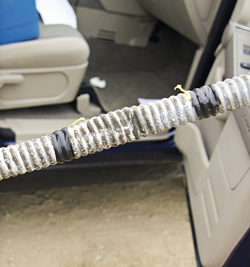 |
| Fig. 9. Cable crimped in tubing slips |
|
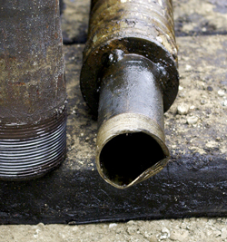 |
| Fig. 10. Anode damaged in BOP stack. Sensor failed 48 hr after startup. |
|
CONCLUSION
The run life of an ESP today should not be measured in months, but rather in years. Run times of five years or more can be expected. The run life of an ESP can be tied directly to the completion, including the successful containment of fines and sands, and a monitoring program that ensures continued optimization of the equipment over its life.
Anodes help mitigate corrosion of the ESP motors, and good chemical programs protect the pump housing and stages, and help to prevent holes in the tubing. These simple steps help ensure that corrosion does not play a role in the failure of the downhole equipment. 
ACKNOWLEDGEMENTS
The authors thank Rick Ropp, Steve Absher and Ron Morin of Warren E&P, Brian Tran and Jason Freeman of Baker Hughes Centrilift, and Van Tai Dang of Schlumberger Artificial Lift for their input.
The authors
KEVIN McCOY is the petroleum engineering manager for Warren E&P, Inc.’s, California fields. Prior to joining Warren, he held positions with several international companies in operational, development and management roles. Mr. McCoy holds a BS degree in mechanical engineering from the University of Manitoba.
BEN NATHAN is the production and completions engineer for Warren E&P, Inc.’s, California fields. He has extensive experience with pumpjacks, ESPs and abandonments. Mr. Nathan holds a BS degree in petroleum engineering from Texas A&M University. |
|


