GORDON MCKINNELL, Stork Technical Services
Preventing corrosion on subsea architecture is critical for operators in their effort to maintain an asset’s integrity and extend field life. Cathodic protection (CP) is a cost-effective solution for the prevention of corrosion as part of a long-term integrity management strategy. With accurate data, it is possible to predict the most likely future state of a structure’s integrity, which assists with effectively planning preventative action.
When a CP system reaches the end of its design life, a retrofit system is often required to ensure an asset’s integrity is not compromised. Stork Technical Services UK Ltd recently engineered and supplied a custom-designed retrofit system to cathodically protect Marathon Oil UK LLC’s West Brae field manifold. The existing system was in need of repair, and the solution had to enable a full-integrity maintenance repair without major disruption to ongoing production.
Developing a CP system. A CP system comprises an anti-corrosion coating and either sacrificial anodes, most commonly used subsea, or impressed current anodes, which are driven by a power unit. CP systems are typically designed to operate for a fixed period of time, usually between 10 and 30 years. However, activities carried out to extend field life, and the addition of facilities to an asset, can impact expected design life. For example, increasing the surface area and members may reduce the effectiveness of the anodes installed as part of the original design.
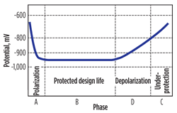
The aim of a CP system (Fig. 1) is to polarize a structure as quickly as possible and maintain the optimum protection for the design life. When depolarization starts to occur, the CP system has exceeded its design life, and either a retrofit system is installed or the structure is allowed to operate under-protected. Under-protection may be allowed under circumstances where installing a new system will overprotect another connected component that has a higher probability of failure.
 |
| Fig. 1. A CP system is designed to polarize a structure as quickly as possible and operate for a fixed period of time. |
|
With overprotection, the materials used must be considered in designing a CP system. Hydrogen blistering, cracking and embrittlement can occur when a system is overprotected, and susceptibility to this kind of damage is dependent on the structure and hardness of the metal in question, e.g., super-duplex steels are most commonly affected in subsea oil and gas applications. As the supply of a high current at a low voltage is central to CP, proper consideration of the equipment and its use must be made to ensure that repeatability and historical traceability are achieved, as well as accurate measuring in the range of <10mV.
Once the system is designed and installed, planned inspections to gather datasets are required to determine if the system has achieved its initial goal of continuously protecting the asset. For most subsea assets, an ROV is equipped with a multi-electrode system to measure potentials and current densities around the asset. Both potential and current density readings are used in detailed analysis of the data. Anode output currents can be calculated from the readings obtained by using an appropriate mathematical model, such as a modified Dwight’s equation or McCoy’s formulae. Historic trend analysis can also be evaluated accurately and used to make meaningful predictions, as the survey system uses a traceable calibration source. All of the gathered data, along with the original design details, allow for an accurate assessment of an asset’s corrosion risk and aids in planning prevention.
Designing for retrofit. The design of a retrofit CP system is based on technical and commercial assessment of each asset, taking into account operational, installation and environmental considerations. An allowance for additional equipment is made in the retrofit design, particularly in the North Sea. While many factors remain similar, each CP system design is different, as current requirements at the cathode depend largely on the environment, particularly the abundance of dissolved oxygen on the metal surface. The type of materials present, the bare surface area of the structure and all associated components exposed to the environment also need to be calculated. Factors which influence this and should be considered as part of the retrofit CP design include:
-
Original design assessment versus actual, current data on the remaining anode mass
-
The asset’s previous and future modifications and usage changes
-
Current density and bare surface area
-
Anode mass requirement—system life and anode electrochemical capacity
-
Anode resistance—various formulas, depending on the anode shape and water resistivity
-
Anode current output—initial, mean and final output as anode depletes
-
Anode positioning—ease of installation and shadowing effects
-
Final checks—number of anodes needed to meet current requirements for design life.
The West Brae manifold. In August 2010, Marathon carried out a routine ROV GVI (general visual inspection)/CP survey of the West Brae field manifold, located in the North Sea. The manifold was installed in 1997, and the manifold’s original design included a CP system of 18 off anodes that were installed onto the structure at manufacture. The CP system had a design life of 15 years. Comparisons with its survey history showed that it had entered the depolarization stage.
Electrical potentials for silver, silver chloride and seawater were becoming more positive, which is linked with the increasing anode wastage levels reported from the visual survey. The levels of anode wastage and readings confirmed that the predicted design life was correct, and the minor shortfall of lifespan was attributed to the addition of new equipment to the manifold after installation.
A retrofit system was commissioned to ensure that CP levels were maintained. A long, slender bracelet design was chosen, since a stand-off or anode sled design could have impacted future tie-ins and current production levels.
Installation locations for the retrofit anodes were determined following a review of existing drawings, future expansion possibilities and inspection campaign footage. The coating condition was considered very good and was consistent with the coating breakdown factors.
Sacrificial anodes made from an aluminum and zinc composition were chosen to protect the manifold and associated steelwork. A conservative approach was taken in the design with regard to coating breakdown, the remaining original anode mass, future additions to the manifold and their effect on the CP system. A standard-sized anode was used to reduce the cost of fabrication and casting. This simplified installation of the units by reducing the number of separate anode and bracket parts to be bolted and electrically connected to the structure. Continuity was achieved by tightening a volcano bolt on the anode band/core bar, which penetrated the surface of the structure-—including paint coating—and closed the electrical circuit.
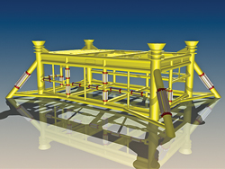
Due to the manifold design complexity and the limited space available, four different sizes of anodes were selected to achieve an effective distribution, Fig. 2. The anodes were distributed to provide an adequate spread and avoid any shadow areas, where the CP current would not flow. Three of the anode designs clamped on as bracelets to members, and a fourth type was designed to clamp onto the core bar of the existing anodes. Anode placement had to take into account several super-duplex fittings which, having a more positive potential CP protection range than steel, could become overprotected and in danger of hydrogen embrittlement.
 |
| Fig. 2. Four custom anode designs were developed to achieve optimum CP levels. |
|
The CP system was installed in April 2011 and is operating successfully. The system will be inspected annually, with ongoing monitoring to ensure correct protection levels across its design life. 
|


