JUSTIN SMITH, Offshore Editor
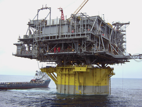 |
| Shell’s Perdido spar in the US Gulf of Mexico. The unit, which is capable of producing up to 100,000 bopd and 200 MMcfd of gas, is located in about 7,400 ft of water in Alaminos Canyon Block 857, and it is currently producing from the first of Shell’s three fields in the area, Great White. |
|
The first step that operators must take when designing the topsides that will go on a floating production unit (FPU) is to establish its functional requirements, such as process, export, drilling and power abilities. These capacities are primarily driven by the reservoir characteristics and fluid properties of the field on which the platform will work.
Reservoir characteristics, including fluid properties, geology, depth below the mudline, connectivity and the presence of a salt layer, determine how many and where on the field wells will be drilled, well production profiles and what recovery mechanisms will need to be implemented. According to a paper presented at this year’s inaugural Offshore Technology Conference (OTC) Brasil by Richard D’Souza and Shiladitya Basu of the front-end engineering consultancy Granherne, these elements “in turn determine the two most important topsides functional requirements: whether or not to have surface or subsea trees and whether to incorporate drilling or workover capability on the platform. These functional requirements fundamentally influence size and weight of topsides and platform selection.”
In an interview with World Oil, Eric Wensel, upstream regional director for the Americas at Mustang Engineering, put it simply, “The overall field development plan is usually the ultimate driver: What does it take to develop the current reservoir and what are the future development options for the owner?”
TOPSIDES’ EFFECT ON HULL DESIGN
“In general, topsides space and weight drive the size of the floating unit,” KBR Senior Vice President Rebel LeBoeuf told World Oil. “The topsides size and weight come first.”
While the hull of a production unit obviously provides the buoyancy that supports the total weight of the systems onboard, including the risers and station-keeping equipment, D’Souza and Basu write that it is really the topsides’ operating weight and center of gravity that are the principal drivers of the hull’s size and configuration as well as how it responds to waves. Hydrostatic stability for a semisubmersible or tension-leg platform (TLP) is also governed by the diameter and separation of the columns, as well as the distance between the deck and the water’s surface, while a spar finds stability through the depth of the keel tank and the quantity of fixed ballast, Fig. 1.
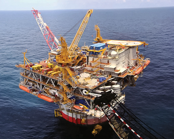 |
| Fig. 1. The Tahiti production facility is a single-piece truss spar operating in the US Gulf of Mexico. Image courtesy of Chevron. |
|
The authors state, “Maintaining the topsides weight and its vertical center of gravity as low as possible for a given functionality will result in a smaller hull and station-keeping system with potentially significant capital cost savings.”
Be that as it may, in some cases, according to John Ellis, upstream project director at Mustang Engineering, the type of hull that is selected is also influenced by issues not related to the topsides facilities. “For example,” Ellis told World Oil, “there may be reasons, such as riser design, that will drive the hull concept toward a conventional TLP solution instead of a spar concept, resulting in a deck that has much more space than is needed for the topsides equipment.”
Ellis also explained that “some deepwater hull concepts are friendlier than others when it comes to space.” For example, the decision to use dry trees vs. wet trees can affect this. “There is no silver bullet,” he said.
IT’S ALL A WEIGHTING GAME
The weight of the topsides has a significant influence on the total capital cost of any FPU. “As space is to weight, weight is to cost,” Ellis said. “Therefore, there’s always a focus on reducing topsides weight as much as possible to provide more options and opportunity to reduce cost.”
D’Souza and Basu feel that assembling a topsides design team with a mindset emphasizing weight reduction in every aspect, without compromising safety and operability, is the single most important strategy to actually achieving lightweight topsides.
One of the most dependable methods operators can use to ensure that the weight of their topsides is efficient, according to D’Souza and Basu, is to set a cap that is dictated by the equipment used to install the equipment on the field.
Reducing topsides weight begins with the design basis, selection and layout of equipment and continuous weight control. “Every ton of equipment and bulk weight saved will result in an equivalent saving in deck steel,” D’Souza and Basu write. They explain that the weight of the bulks, which include components such as pipes, valves, supplies, cables and trays, generally equals equipment weight. These bulks create the greatest weight uncertainty and can be difficult to manage.
For floating production platforms with a drilling rig installed, conventionally designed and packaged rigs add a considerable amount of weight, but that can be reduced somewhat if the topsides design team specifies a lightweight, self-erecting drilling package. In addition, D’Souza and Basu explain that “tensioner loads of top tensioned risers are a major driver of deck weight and topsides payload.”
Both wet and dry trees require large volumes of chemicals and fluids for flow assurance in flowlines and risers. Many of these fluids, including methanol and dead oil, can be stored in the hull, which both reduces topsides weight by a substantial margin and lowers the unit’s vertical center of gravity.
While it is necessary to use these contingencies and margins to scale back the weight of the topsides, D’Souza and Basu warn that they must be used judiciously: “Excessive contingencies result in overdesigned decks and hulls and lead to an unwarranted increase in capital costs.”
More importantly, any alternative that leads to the platform being lighter, but at the expense of safety, is not a viable option. LeBoeuf explains that controlling weight plays a primary role in the design of topsides, but safety always comes first. “An engineer can have a great weight-saving idea, but if it fails the safety test, the idea will not go any further,” he said.
MAXIMIZING SPACE THROUGH INTELLIGENT LAYOUT
Topsides design involves coordinating and integrating a large multitude of operations, such as process, mechanical, electrical, piping, instrumentation, architecture, structures, marine, drilling and safety. All of these elements have an impact on and, conversely, are impacted by the layout of the topsides on the deck.
As would be expected, the type of unit dictates the maximum deck footprint. A spar’s deck is limited by its hull diameter, which is determined by the operating parameters of the topsides. The hull diameter of a spar can range from about 70 ft to 125 ft, resulting in corresponding deck footprints of about 140 ft × 140 ft and 200 ft × 200 ft, respectively.
The deck footprint of a semisubmersible or TLP can be 50–60% larger than that of a spar with the same topside payload. The diameter and separation of a semi or TLP’s columns, which are also influenced by the topside’s operating parameters, determine the maximum deck footprint for those types of units. A center-to-center column separation of 140 ft × 140 ft and 40-ft-diameter columns will yield a deck size of about 170 ft × 170 ft, while a 200-ft × 200-ft hull with 70-ft-diameter columns has a corresponding deck footprint of about 250 ft × 250 ft.
The two fundamental deck configurations, integrated and modular, both have strengths and weaknesses. An integrated deck, which uses the global strength of the platform’s orthogonal trusses to resist gravity and wave-induced dynamic loads, can be fabricated in single or multiple sections depending on the weight and size of the deck and the installation option selected.
For larger topsides, operators often employ a modular deck, which consists of a module support frame that, with the hull structure, provides the global strength of the platform. Individual modules are set on the frame and transfer their gravity and inertial loads to it, but do not participate in global structural response. Modular decks are less efficient than integrated decks, but they provide greater flexibility for the layout and possible future expansion of the topsides.
HEAVY LIFTING
Topsides and decks, whether they are integrated or modular, have to be installed onto the hull. For spars or smaller TLPs, topsides installation is generally executed offshore by a heavy-lift vessel, Fig. 2. Topsides for semis and conventional TLPs, on the other hand, are usually performed quayside by special heavy-lift shear leg cranes.
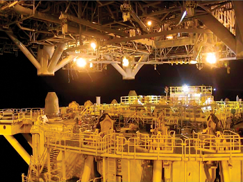 |
| Fig. 2. The topsides of Shell’s Perdido spar being lowered into place in March 2009. |
|
Due to the small number of available slots to use heavy-lift cranes, the topsides installation, integration and commissioning strategy must be solidified early in the design phase. Said Wensel, “Geographic location and season of installation can be a big driver due to availability of heavy-lift equipment.”
Weight budgets for topsides decks or modules are also set by the lift capacity of these cranes or the barges on which they are transported. Through this, the operator is able to avoid the costly activities of offshore hookup and commissioning that are associated with multiple lifts.
“When topsides dry weight exceeds the capacity of the largest crane vessel, which is usually the case for a dry-tree drilling spar, then multiple offshore heavy lifts are necessary,” D’Souza and Basu write. “These are expensive and entail significant risk of delay of first oil because of weather standby.”
Since semis and conventional TLP hulls are column-stabilized, they can be wet-towed to the field after the topsides have been installed and commissioned quayside. D’Souza and Basu write, “Integration and commissioning, as well as decommissioning, of topsides to the hull is a major differentiator between spars and semisubmersibles or TLPs as the offshore installation for the former carries greater cost, schedule and safety risks than the quayside installation for the latter and is a major consideration in platform screening and selection.”
When it comes to floatover installations, the weather and sea conditions play a larger role. “Floatover installations are heavily dependent on environmental conditions,” Wensel said. “Therefore, geographic location can affect topsides concept selection.”
That said, this method, while a popular choice for decades for shallow-water platform installations, has only seen deepwater applications emerge in the last few years. Figure 3 illustrates a floatover operation planned to set topsides on the hull for ATP’s Cheviot field in the UK North Sea. Ellis said that while the North Sea environment is a pretty rough area and not generally conducive to floatover installations, this operation will be done in the protected waters of a Norwegian fjord. Afterward, the unit will be commissioned and then wet-towed to the field.
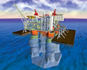 |
| Fig. 3. The Cheviot topsides will be installed onto the Octabuoy dry-tree semi using the floatover technique, which is a rarity for the North Sea. Image courtesy of ATP Oil & Gas. |
|
“All FPUs have their sweet spot and their method of installation,” LeBoeuf said. “All installations have challenges, and they are resolved by creative designs. Methods of installations are driven by the size and weight of the topsides and the type of hull.”
PERDIDO AND HELIX PRODUCER I
Illustrating the various techniques that can go into designing and installing topsides are two units that are now working in the US Gulf of Mexico: the Perdido spar and the Helix Producer I, a ship-shaped FPU.
The Perdido spar, located in about 7,400-ft waters in Alaminos Canyon Block 857, is currently producing from the first of Shell’s three fields in the area, Great White. The unit is capable of producing 100,000 bopd and 200 MMcfd of gas.
According to a paper by Kurt Shallenberger and Keith Smith of Shell presented at the 2010 OTC in Houston, the “Perdido topsides was designed to deliver high producing and drilling functionality while capturing the benefits of a single offshore lift module concept.”
Initially the Perdido design team focused on improvement in the higher-weight structural and equipment categories, but it became apparent that, due to thousands of small items, the bulks category had the greatest uncertainty. In addition, the designers recognized early on that the loadout and transport strength of the topsides would push the transport barge, Otto Candies’ OC-4126, to its limit.
The Perdido topsides were designed to fit just within the capability of Heerema’s deepwater construction vessel Thialf, which performed the lift of Perdido’s topsides, setting a record for the heaviest single-piece lift in the US Gulf of Mexico at 9,773 tons. In the end, Shallenberger and Smith write, “the physical lift weight barrier was a firmer control of change than a typical cost/benefit control process.”
After Hurricane Rita capsized and destroyed the Typhoon TLP in 2005, the field’s new operator, Helix Energy Resource Technology, opted to develop the field using a ship-shaped FPU, a first for the region. Converted from the ferry MV Karl Carstens, the Helix Producer I is producing 30,000 bopd and 72 MMcfd from the renamed Phoenix field in over 8,800 ft of water in Green Canyon Block 237.
Since the unit was repurposed from an existing vessel, as opposed to being purpose-built, many of the existing vessel systems remained intact. In a paper presented at this year’s OTC in Houston, Jay Chen, Chris Hartmann and Bryan Margo of Oil Field Development Engineering, the FPU’s topside designers, along with Helix’s Tony Owen, write that, to minimize the changes required in the ship’s conversion, “it was decided that no process equipment or hydrocarbon storage would be allowed below the weather deck of the vessel.”
This decision forced the designers to take space-saving measures like choosing small-footprint equipment, stacking equipment, and limiting spare equipment on the vessel.
NEW TECHNOLOGIES BOTH SOLVE AND CREATE ISSUES
The water depths in which operators are developing fields continue to get deeper, and while the oil is there to make these costly developments profitable, technological advances are helping to ensure that operators get the most from their investments.
Shifting some of the topside equipment to the seafloor can help counter issues that arise with topside design, but those technologies are not completely field-tested yet. “Subsea production is an emerging technology that may eventually reduce the need for some topsides equipment,” Wensel said. “Reliability and access issues remain a challenge for utilizing subsea equipment for some functions.”
However, transferring equipment to the seafloor is not the only advancement taking place in terms of topsides. Other new technologies are having impacts, both good and bad, on topsides, with a trend toward more complex facilities.
According to Ellis, some technologies are making things easier. Among these, three-phase metering allows operators to reduce some topsides equipment; advances in automation are improving uptime and reducing the number of personnel required on the unit; and 3D design software is improving deck layouts, granting operators the ability to arrange more equipment in a smaller topsides footprint.
Other emerging technologies are creating new hurdles for deepwater operators. Ellis pointed out that increasing numbers of remote facilities are requiring additional space and equipment for operations; deeper water depths and longer tiebacks require additional equipment or technology to support flow assurance needs; and deeper wells bring with them higher pressures and temperatures that require more robust riser and topside equipment designs. 
Beyond rust, coatings protect against fire and ice
In general, the protective coatings that are applied to topsides must protect the asset against two dangers: destruction by corrosion and fires. A number of such coatings exist, but intumescent coatings provide passive fire protection (PFP) by rapidly swelling in reaction to a blaze, creating a thick char barrier that protects a steel substrate from structural failure.
According to Bruce Toews, market director for petrochemicals and offshore at Sherwin-Williams Protective & Marine Coatings, PFP applications for hydrocarbon structures require coating thicknesses between 0.15 and 1.1 in., depending on steel thickness and fire rating, and average about 0.4 in. “Maintenance and repair to coatings of this thickness are expensive and time consuming,” Toews told World Oil. “Coatings meeting NORSOK testing standards will perform as expected with negligible or minimum maintenance to areas where mechanical damage has been caused for whatever reason.”
Toews said that his company’s Firetex brand of epoxy intumescent coatings helps owners achieve the fire resistance ratings necessary for a sound PFP system. When used in conjunction with thermal barrier products, such coatings can provide protection against both sub-zero (such as in the case of cryogenic spillage) and elevated temperatures, extending the operational range of the topsides.
Since coatings like these are valuable relative to the fire resistance they possess, they require extensive testing to determine their surface burning characteristics, specifically the flame spread and smoke index when exposed to fire. One such test saw several I-section steel columns coated, after which 13 were immersed in saltwater while the remaining column was left unexposed as a control. After various periods of immersion, including one in excess of 14 years, each section was fire-tested to the hydrocarbon curve and its result compared against the control sample.
Said Toews, “Using PFP coatings that pass this test where required on the structure will not only afford PFP protection for the design life of the asset, but also dramatically reduce the need for maintenance because of the high grade of corrosion resistance properties in the formulation.”
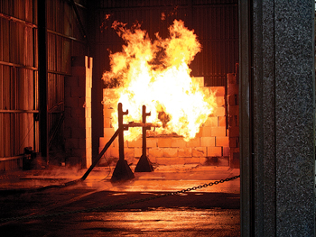 |
| A steel column, after being covered with an intumescent coating, undergoes a fire test. Image courtesy of Sherwin-Williams. |
|
|
|


