The venturi-nozzle, or simply venturi, gas lift valve is increasingly being used in continuous gas lift wells worldwide.1–4 In Brazil, about 250 offshore wells are now equipped with these valves.
Two types of gas lift valves are typically used in the oil and gas industry. The first type uses a mechanism, usually a charged bellows, to open or close the valve according to wellbore pressure and/or temperature. The second type involves valves that are always open (in the casing-to-tubing direction). They are composed of a choke to restrict the flowrate and a check valve to avoid reverse flow from tubing to casing. The most widely used choke is a cylindrical plate with a square-edged orifice. Alternatively, a choke with a venturi geometry may be used.
Subsea wells tend to employ single-point injection, and the venturi valve has been preferred, not only because of its flow characteristics but also because its external check valve has proven more robust than the internal check valve usually present in orifice valves. In the internal check valves, the dart rotates and vibrates; after a certain number of cycles, its legs often break and the dart turns upside down, blocking the gas passage and, in effect, working as a check valve in the wrong direction. For wells with high gas injection rates, this breakage may happen very quickly, necessitating a premature intervention, which is very expensive in subsea wells, accompanied by significant production loss if there is a shortage of rigs.
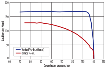 |
| Fig. 1. Dynamic performance comparison between two commercial 1½-in.-OD venturi and orifice gas lift valves at standard conditions (atmospheric pressure and 20°C). The curves were obtained at Petrobras’ Gas Lift Test Unit in Aracaju, Brazil, with natural gas and 140-bar upstream gauge pressure. |
|
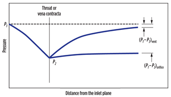 |
| Fig. 2. Pressure profiles along the gas path through a venturi or an orifice. |
|
BACKGROUND
Figure 1 shows an experimental gas flow curve of a venturi valve compared with that of a conventional square-edged orifice valve. The most important difference relates to critical flow—i.e., the region of the curve where the gas flowrate through the valve is constant, irrespective of downstream pressure. This occurs when downstream pressure is less than a certain fraction of the upstream pressure. This fraction, called critical ratio, is roughly 0.5 for an orifice valve and 0.9 for a venturi valve. Thus, in view of the usual pressure differentials between casing (injection pressure) and tubing (production pressure), orifice valves operate under a subcritical flow regime and venturi valves under critical flow.
That difference may be better explained using Fig. 2, which schematically compares pressure profiles for both venturi and orifice valves in the case of subcritical flow. The pressure decreases from P1, the injection pressure in the casing (neglecting pressure drop at inlet ports of the mandrel and of the valve itself) to P2, the pressure at the main flow restriction—the orifice vena contracta or the venturi throat. The behavior upstream of the restriction is similar in both situations (disregarding some effects resulting from the abrupt contraction upstream of the square-edged orifice). Downstream, however, the venturi diffuser promotes a great pressure recovery from P2 to P3, the production pressure in the tubing (neglecting pressure drop at outlet ports and at the check valve). In turn, such recovery is very small for the orifice.
Hence, to reach the same pressure P2 at the main flow restriction, a much lower pressure P3 will be required using an orifice instead of a venturi. Conversely, for the same pressure P3 the corresponding pressure P2 is considerably lower in the venturi than in the orifice choke. If the throat and orifice areas are the same, it basically means that for the same tubing pressure P3 the gas flowrate is greater for the venturi than for the orifice.
If tubing pressure P3 is steadily reduced, critical flow will eventually be established and pressure P2 will assume its critical value P2c. At this point, the corresponding tubing pressure is the critical tubing pressure P3c. As previously discussed, P3c is much greater for the venturi due to the remarkable pressure recovery at the diffuser.
Additional tubing pressure reductions will not affect conditions at the main restriction, and gas flowrate will remain constant. The key point is that the difference in pressure recovery downstream of the main flow restriction is responsible for the different performance curves of venturi and orifice valves.
Another difference is the orifice’s lower critical gas flowrate when compared with a venturi that has the same throat diameter and is submitted to the same upstream conditions and gas. The main reason for this difference is the presence of a vena contracta downstream of the orifice. It is originated by swirling eddies formed after the sudden expansion. The main jet from the orifice is then contracted, forming the vena contracta, which is the smallest flow area, Fig. 3. In a venturi, the smallest flow area is the throat area itself.
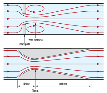 |
| Fig. 3. Schematic streamlines for gas subcritical flow through an orifice (top, showing the vena contracta) and a venturi. In critical flow, a shock wave will appear somewhere downstream of the vena contracta or throat, but streamlines upstream will present the same comparative behavior. |
|
Since most advantages of a venturi valve come from the high critical ratio, which depends on valve design, we define a valve as being a venturi valve if the critical ratio is 0.9 or greater, considering the gas and pressure-temperature conditions of the actual application. In theory, venturi valves may be used in all wells producing by continuous gas lift. In practice, some factors may prevail that call for orifice valves instead.
CONTROLLING UNSTABLE FLOW
In a gas lift well, severe flow instabilities may occur, and beyond certain limits they can cause shutdown in process plants and other operational problems. Moreover, unstable wells may prevent automatic field optimization schemes from working properly and, thus, may have to be excluded from these schemes. Methods to control such instabilities generally result in production losses and/or higher operational costs.
Those instabilities are generally caused by three mechanisms, the most usual being casing heading. In this case, gas flow through the operating gas lift valve is subcritical and disturbances in production pressure cause changes in gas flowrate through the valve. Thus, the gas flow dynamics in the casing-tubing annulus become linked with tubing flow dynamics. Under certain conditions, these variations in flowrates and pressures are amplified and perpetuated, resulting in unstable well flow. Depending on system configuration, other wells may be affected, too.
Even before the market availability of venturi valves, operating under critical flow at the gas lift valve was a recognized means to avoid casing heading, since in this case the gas injection flowrate would not be affected by fluctuations in tubing pressure.5–7 However, it was not considered practical or economical due to the huge pressure differential between casing and tubing required to achieve critical flow through orifice valves. In contrast, such pressure differential is relatively small for venturi valves, so naturally one of the most important advantages of venturi valves is to prevent flow instabilities caused by casing heading.
A second instability mechanism is density wave,7,8 which can occur even with critical flow through gas lift valve—i.e., despite constant gas injection flowrate. Variations in fluid intake into the well cause variations in the density of the mixture being produced. That disturbance propagates through the tubing as a density wave. In theory, the system will self-regulate, because an increase in liquid flowrate will increase the fluid density inside the tubing, causing higher formation backpressure and, thus, a reduction in the liquid flow and fluid density. A similar stabilization process would occur in the event of a reduction in the liquid flow. However, this natural stabilization process is delayed due to the propagation time of disturbances along the well, and, depending on conditions, a strong cyclical instability can be established. This type of instability is associated with deep wells producing from depleted reservoirs, and the venturi valve does not solve the problem.8
Subsea wells with flowlines on hilly terrain or descending toward the platform represent another threat in terms of unstable flow. Severe slugging may occur under certain conditions and independently of the gas lift valve adopted. One possible solution is to increase gas flowrate. Venturi valves may help here, because they allow a substantial increase in gas flowrate, as discussed below. Besides, maintenance of critical flow avoids the introduction of a new possible source of instabilities.
HIGHER GAS FLOW RATE
As seen above, replacing an orifice valve operating in subcritical flow with a venturi one results in a gas flowrate increase that may be enormous if the throat area is the same as the original orifice. Thus, venturi valves generally have smaller throat areas than the corresponding orifices for the same application. An estimate of the throat diameter that corresponds to a given orifice may be obtained by taking 90% of the orifice diameter and multiplying the result by the square root of the ratio between actual and critical flowrates for that orifice. For example, a 9.5-mm orifice operating at 200 bar and 80°C upstream with a gas of 0.75 specific gravity and 25-bar pressure differential across the valve would likely be replaced by a venturi of 7.0-mm throat.
However, in several applications the objective is just to increase flowrate across the valve. Limitations in maximum available pressure differential may exist, reducing the maximum gas flowrate that can be reached with the given orifice valve. Such limitations may be caused by compressor constraints, uncertainties in some parameters assumed during gas lift string design, partial obstruction at some point in the gas flow path and other causes. Although orifices up to ½ in. may be used in 1½-in.-OD valves, fear of introducing instability has limited orifice diameters that designers will specify for small pressure differentials.
The belief that smaller orifices are conducive to stability comes from the performance curve shape. As the orifice increases, the variation in gas flowrate for a given reduction in tubing pressure becomes larger (i.e., smaller orifices play a better role as a control to disturbances in tubing pressure).5 Thus, to inject more gas with an orifice valve in that situation, it is necessary to inject with a greater pressure differential at a shallower depth, which probably means a rig intervention to change the string and a less-efficient gas lift. Replacing the orifice valve with a properly sized venturi valve generally solves this problem effectively.
Conversely, because a venturi valve requires a smaller pressure differential to inject the desired amount of gas in a stable manner, the injection point may be deeper, resulting in increased production, Fig. 4. Alternatively, if the injection point is the deepest possible, injection pressure may be reduced. If injection pressure reduction is accompanied by a reduction in the compressor suction pressure and, hence, in separation pressure, it may lead to increased flow from the wells.
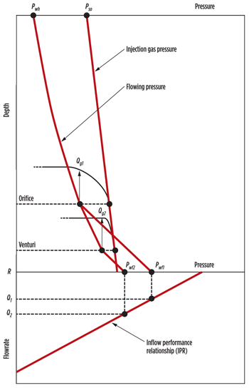 |
| Fig. 4. This illustrative graph combines pressure profiles, valve performance and reservoir inflow to show how the injection point may deepen with a venturi valve. The orifice valve is set at a depth that results in a flowing pressure Pwf1 at reservoir depth R, which results in a liquid flowrate Q1 according to the inflow performance relationship. Assuming that it is not possible or advisable to increase the orifice size, since the venturi valve may inject the required amount of gas with a small pressure differential and in critical flow, it may be set at a deeper point, resulting in a reduced flowing pressure Pwf2 and an increased flowrate Q2. |
|
DUAL COMPLETIONS
In oil fields with more than one producing zone, dual-completion schemes for producing the reservoirs via separate strings inside the same well have a strong appeal due to the reduction of investment required. However, production of these wells often presents operational problems that can reduce or eliminate the potential gains. In dual completions with continuous gas lift, the venturi valve contributes to the optimization and stability due to the ease of reaching critical flow and, thus, constant injection gas flowrate. Disturbances that occur in one string do not affect the other string.
Moreover, venturi valves improve overall production monitoring. In wells with an orifice valve operating in subcritical flow, it is difficult to calculate precisely how much gas is being injected because it depends strongly on tubing pressure, which usually is only estimated and may oscillate considerably. However, that problem can be overcome by measuring the gas flowrate directly. In dual completions, even when total gas flowrate is measured, the gas distribution between strings is not known and is difficult to estimate. As a consequence, how much associated gas is being produced by each string is not accurately known. With venturi valves, gas injection flowrate into each string is almost constant and is much more predictable with a good model.9,10 If the operating valves of both strings are close in depth and the total injected gas is measured, the flowrate through each valve can be reasonably estimated by dividing the total rate proportionally to the throat areas of each valve. If the valves are at widely different depths, a small adjustment can be made using the calculation model.
LESS FLEXIBILILITY
Figure 5 illustrates one of the main reasons why the orifice valve is sometimes preferred. For a hypothetical well, lift gas flowrates were calculated using an artificial lift simulator as a function of injection pressure at the platform (i.e., the sensitivity of gas flowrate as a function of injection pressure) for two situations: a valve with an 8.0-mm orifice and a venturi valve with a 6.4-mm throat. The diameters are different because the two valves inject the same amount of gas required at the operating point (132.4 bar with 126.7 Mcmd of gas). It may be noted that the venturi valve is less sensitive to casing pressure changes than the orifice valve. For the same injection pressure variation around the operating point (about ±6 bar), a variation in gas flowrate from −12% to +9% of the designed flowrate is obtained for the orifice valve. In the case of venturi valve, the corresponding variation is from −5% to +5%.
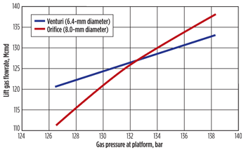 |
| Fig. 5. Comparison between orifice and venturi valves in terms of sensitivity to gas injection pressure for a hypothetical subsea well (gas flowrate at standard conditions). |
|
That difference in sensitivity to injection pressure can be better visualized with the aid of Fig. 6. The performance curves for gas injection pressures of 132.4 bar and 127.5 bar are plotted for both valves. The curves have been transposed to valve depth conditions (the injection pressure of 132.4 bar at the surface, for example, results in a casing pressure of 187.9 bar in front of the valve). The points used to draw the curves were also obtained by successive simulations and, therefore, incorporate all factors influencing them. The operating point (Point 1) is highlighted in red. If tubing pressure remained constant at Pt1 after injection pressure was reduced, the new operating point for the venturi valve would be Point 2 and, for the orifice valve, Point 4. This alone would represent a difference in the injection flow between the two valves for the new injection pressure. But beyond this, the smallest injection of gas causes an increase in tubing pressure. Thus, for the venturi valve, the operating point, instead of being Point 2, will be Point 3. However, this does not affect the injection flowrate, as the valve continues to operate in critical flow. The injection flowrate depends on injection pressure only and is not influenced by tubing pressure. For the orifice valve, on the other hand, this increase in tubing pressure shifts the operating point considerably, from Point 4 to Point 5, amplifying the reduction in gas injection.
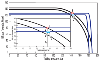 |
| Fig. 6. The difference in sensitivity to gas injection pressure is explained by the difference in performance curves between orifice and venturi valves (gas flowrate at standard conditions). |
|
That difference in sensitivity to injection pressure is a function of the location of the operating point on the performance curve of the orifice valve. The closer this point is to the subcritical-critical transition, the closer are the sensitivities of the two kinds of valves.
The practical effect of that difference in sensitivity will depend on the response of the well to the variation in gas flowrate. In general, it is preferred to inject gas close to the presumed optimum. For the present example, the 6-bar variation in injection pressure around the operating point represents a variation of produced liquid flowrate ranging from the variation of −1.8% to +1.2% for the orifice valve and ±0.7% for the venturi valve. For operating points closer to the “optimal” point, the practical effect of the difference between sensitivities would become even less important.
OTHER LIMITATIONS
A venturi is more complex to manufacture and requires more material than a simple orifice plate, and it is therefore more expensive. Other factors also contribute to the higher cost of venturi valves, such as “high-tech” appeal.
Blockage risk. Any existing debris in the gas stream is naturally led to the venturi throat, where it may lodge and cause a reduction in gas injection. This may also occur with an orifice valve, but there the debris may stick to another part of the plate without provoking significant flow restriction. Moreover, as discussed above, for the same gas flowrate the orifice diameter is greater than the corresponding throat diameter, allowing passage of larger debris. Restriction due to debris is a rare event (about 0.2% probability, in the author’s experience) and may be controlled, but it may be a concern in old gas lift installations with known problems regarding lift gas quality.
Subcritical region. If variations in tubing pressure are such that subcritical flow takes place, strong oscillations in gas injection flowrate may occur, causing strong instabilities. Appropriate venturi and valve design helps since the subcritical region is reduced to a minimum. But in cases were there is a high risk of operating in subcritical flow, such issues may counter-indicate venturi valves.
During kickoff, venturi valves function in subcritical flow for short periods of time. The effect of that occurrence on the kickoff process is not established, but no problems related to this period of subcritical flow have been reported. On the contrary, venturi valves are considered better than orifice valves for kickoff because they are more resistant to erosion11 and allow steady-state operation to be reached more quickly.
PERFORMANCE CONCERNS
In a venturi valve, some design requirements must be fulfilled to guarantee the desired performance. Not only must the venturi itself follow an appropriate profile and finishing, but the entry ports and the check valve must introduce as small pressure losses as possible. Venturi involves a well-known geometry, but details of the specific profile make a big difference. Experimental performance curves and subsequent analysis have revealed design mistakes in some commercial venturi valves with negative effects on parameters such as critical ratio.
The venturi inner surface finishing is important and will directly influence pressure recovery through the diffuser. The venturi should be visually inspected to ensure that there is no defect, especially at or near the transition between the nozzle and the throat and between the throat and the diffuser.
Tight tolerance in throat diameter is also important since operation in critical flow means that flowrate is directly proportional to the throat area. For a prescribed tolerance in the critical flowrate, an equal dimensional tolerance in the throat area (i.e., a tolerance half as large in the throat diameter) is required. It is also advisable to check the real throat diameter with the manufacturers since some difference from the nominal one may occur due to fabrication issues.
A good venturi design is not sufficient. The overall valve critical ratio may be severely affected by local pressure losses at entry ports and at check valves/exit ports. More and larger entry ports are required in comparison with conventional orifice valves. The entry section has to present an external diameter smaller than the rest of the valve body, allowing a sufficiently large annular area between the valve housing in the mandrel and the valve itself. The check valve must have a gas passage area as large as possible.12 Additionally, internal channels of the valve as a whole should be expanded. It is also a good idea to review the mandrel, because larger entry orifices and gas passage areas would probably be beneficial, particularly for high gas flowrates.
Even a well designed venturi valve has a gas flowrate limit beyond which the performance degrades, especially in terms of the critical ratio. Although pressure and temperature conditions influence these limits, it is recommended to limit throat diameters to 8.0 mm (5/16 in.) for 1-in.-OD valves and 9.5 mm (⅜ in.) for 1½-in.-OD valves. Larger throats may be used, but the gas lift engineer has to take into account that it will probably result in critical ratios lower than 0.90. 
LITERATURE CITED
1. Tokar, T., Schmidt, Z. and Tuckness, C., “New Gas Lift Valve Design Stabilizes Injection Rates: Case Studies,” SPE 36597 presented at SPE Annual Tech. Conf. & Exhb., Denver, Oct. 6-9, 1996.
2. Faustinelli, J., Bermúdez, G. and Cuauro, A., “A Solution to Instability Problems in Continuous Gas-Lift Wells Offshore Lake Maracaibo,” SPE 53959 presented at SPE Latin Am. & Caribb. Petrl. Eng. Conf., Caracas, April 21-23, 1999.
3. Lyngholm, A., et al., “Technology Extends Gas Lift Reach,” World Oil, April 2007, pp. 95-98.
4. Kartoatmodjo, G., et al., “An Integrated Approach to Field Surveillance Improves Efficiency in Gas Lift Optimization in Bokor Field, East Malaysia,” IPTC 12225 presented at Int. Petr. Tech. Conference, Kuala Lumpur, Dec. 3-5, 2008.
5. Grupping, A.W., Luca, C.W.F. and Vermeulen, F.D., “These Methods Can Eliminate or Control Annulus Heading,” Oil & Gas Journal, July 30, 1984, pp. 186-192.
6. Moore, P.C. and Adair, P., “Dual Concentric Gas-Lift Completion Design for the Thistle Field,” SPE 18391, SPE Production Engineering, 6, No. 1, February 1991, pp. 102-108.
7. Alhanati, F.J.S., Schmidt, Z., Doty, D.R. and Lagerlef, D.D., “Continuous Gas-Lift Instability: Diagnosis, Criteria, and Solutions,” SPE 26554 presented at SPE Annual Tech. Conf. & Exhib., Houston, October 3-6, 1993.
8. Hu, B. and Golan, M., “Gas-Lift Instability Resulted Production Loss and Its Remedy by Feedback Control: Dynamical Simulation Results,” SPE 84917 presented at SPE Int. IOR Conf. in Asia Pacific, Kuala Lumpur, October 20-21, 2003.
9. Almeida, A.R., “A Model to Calculate the Theoretical Critical Flow Rate through Venturi Gas Lift Valves,” SPE 126184-MS, SPE J., 16, No. 1, March 2011.
10. Almeida, A.R., “Calculating Gas Flow Rates Through Venturi Valves,” Oil & Gas Journal, 108, No. 5, Feb. 08, 2010, pp. 41-45.
11. Ribeiro, P.J.P. and Lima, F.S., “Erosion Speed Effects on Gas Lift Valves in Well Unloading Operations,” presented at 32nd Gas Lift Workshop, ASME/API/ISO, The Hague, Feb. 2-6, 2009 (available through www.alrdc.org ).
12. Almeida, A.R. and Mendes, R., “Optimizing Gas Lift Equipment with CFD Techniques,” presented at 31st Gas Lift Workshop, ASME/API/ISO, Houston, Feb. 4-8, 2008 (available through www.alrdc.org ).
|
|
ALCINO R. ALMEIDA is a Senior Petroleum Engineer with Petrobras’ Cenpes research and development center in Rio de Janeiro, Brazil. He specializes in gas lift optimization, including new equipment engineering, flow modeling and software development. He joined Petrobras in 1984 and Cenpes in 1988. Mr. Almeida holds BS and MS degrees in mechanical engineering from Federal University of Rio de Janeiro. / alcino@petrobras.com.br
|
|
| |
| |
| |
|


