| ALI DANESHY, Contributing Editor, Shale Technology
Dual-injection frac systems include either a coiled or standard tubing string inside the casing and allow fluid injection through both the internal string and the casing-tubing annulus. In most industrial applications, the internal string is coiled tubing (CT), and that is what we will assume for the rest of this article. All the discussions presented here are equally true if the internal string is regular tubing.
Dual-injection frac systems are available for both openhole and cased-hole completions. The common practice is to pump the slurry through one conduit (tubing or annulus), while maintaining a low injection rate through the other (usually referred to as the “dead” string). However, both strings are always available for pumping and are often used to address special situations.
Important benefits of these systems include the following:
Versatility. The ability to pump through both strings adds substantial versatility in performing the frac job. One can easily, and almost instantly, change and manipulate the fluid mixture injected into the fracture, without having to wait until the surface changes are displaced to the perforation depth. For example, in foam frac jobs one can inject the gaseous phase through one conduit and the proppant-laden slurry through the other. The mixture of the two streams causes foam to be formed right at the perforations and then injected inside the fracture. The bottomhole foam quality (percentage of gaseous phase) can instantly be changed by varying the injection rate of the gaseous phase. Similarly, one can instantly change proppant concentration at the fracture depth by adjusting the injection rates of proppant-laden slurry (which is pumped through one conduit) and clean fluid (pumped through the other conduit) at the surface. In the extreme, pumping of proppant into the fracture can immediately be stopped by halting the slurry injection, while continuing (or increasing) injection of clean fluid through the other conduit. The ability to mix two fluid streams at the perforation depth opens the door for many creative adjustments of the fracturing treatments.
Flexibility. Dual injection enables the option of circulating the fracturing slurry out of the wellbore and cleaning the well. This is usually done by increasing the injection rate through the dead string and reverse-circulating the slurry out of the wellbore. This is particularly useful in horizontal wells where, if the proppant stays dormant, it can settle and collect at the bottom of the well and prevent or obstruct subsequent movement of completion equipment. Another advantage of this option is faster and lower-cost operations.
Bottomhole pressure read-out. The low injection rate through the dead string generates very low friction pressure. Thus, adding the hydrostatic pressure to the value measured at the surface for the dead string provides a very good indication of the fracturing pressure at the perforations. This data provides an excellent indication of what is happening inside the fracture. Furthermore, comparing the pressure of the two conduits can provide a reasonable sense of the consistency of the injected fracturing slurry.
The limitations of dual-injection systems include lower injection rates and depth limitations. The reduced conduit flow area limits the maximum injection rates that can be obtained. The actual achievable rates depend on the size of the casing and the CT, and which conduit is used for slurry injection. The depth limitation results from availability of long CT strings and their pressure limitations.
This article discusses some of the available industrial systems for both open and cased holes.
Hydra-jet openhole system. These systems include a hydra-jet perforating assembly at the end of the CT string.1 Injecting abrasive slurry (usually a mixture of water, about 1-lb/gal frac sand and a friction reducer) through small-diameter nozzles (usually 3/16 in.) creates large perforations in the formation, Fig. 1.
 |
| Fig. 1. Schematic of a hydra-jet perforating and fracturing system. |
|
The nozzles are usually located within a few inches of each other. The perforations assure the location of the fracture within the horizontal well. The high velocity of the fluid stream exiting the nozzles also creates a pressure differential between the wellbore and the fracture that prevents fluid from moving within the annulus. This creates a hydraulic isolation system that removes the need for mechanical isolation within the wellbore, such as openhole packers. The actual frac treatment consists of the continuation of the slurry injection through the CT at higher rates and proppant concentrations. Simultaneously, a clean fluid (usually a linear gel) is injected through the annulus at very low rates (usually on the order of 0.1 bbl/min.). Thus, the annulus serves as the dead string, and its surface pressure provides a very good indication of the fracturing pressure at the perforations. At the end of the planned fracturing, the CT moves uphole to its next target location and the perf-and-frac sequence is repeated.
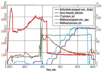
Figure 2 shows an example of such a treatment. The first injection stage is the perforation process, while the second is the frac treatment itself. The graph shows relatively flat bottomhole pressure (annular data) while the treatment pressure changes in response to variations in friction and changes in hydrostatic head.
 |
| Fig. 2. Example of a hydra-jet perforating and fracturing operation. |
|
Injection through CT limits the maximum rate achievable with these systems, especially in longer horizontal wells. In some cases, when higher rates are desirable, it is possible to inject through both strings. In these cases the slurry is usually injected through the CT while clean fluid is pumped through the annulus. The combined injection offers somewhat higher, but still limited, rate capability.
Besides all of the advantages listed earlier for all dual-injection systems, some advantages specific to the hydra-jet system are as follows:
Accurate fracture location. One of the concerns with fracturing open holes is the uncertainty of fracture location, which can be anywhere within the isolated pressurized interval. Perforating the well ensures the fracture location. This is a very important advantage of this system and helps create the desired drainage pattern in the reservoir.
Robust fracture initiation and extension. The closeness and larger size of the perforations create a favorable condition for simpler fracture initiation and extension. A fracture is more likely to initiate in its preferred plane without the need for re-orientation away from the wellbore. This also allows injection of higher proppant concentrations and amounts.
Simple installation. Since this system does not require a liner or openhole packers, it is easier to install.
Limitations of the system include the following:
Low injection rate. The friction pressure due to flow through the nozzles adds to the slurry friction pressure inside the CT and creates higher surface injection pressures. This limits the fracturing injection rate.
Nozzle wear. Pumping large volume of proppant wears and enlarges the nozzles. In practice, the CT is brought back to surface after several frac stages and the worn nozzles are replaced. Nozzle life depends on the total amount of proppant pumped through it. Proppant weights of more than 2 million lb are known to have been pumped through one set of nozzles before the need for replacement.
Higher tendency for proppant flowback. The simpler fracture path also makes it easier for proppant flowback after the treatment.
More completion options are commercially available for cased holes. Below we provide a discussion of some of the more prominent systems.
Packerless hydra-jet. The system discussed above can also be deployed for cased holes. The details are exactly the same.
The perforation process takes longer in cased-hole applications. Furthermore, the high-velocity abrasive bounces back after impacting the casing at the beginning of the perforation process. This can damage the nozzles or the CT, and may even create a pinhole in it. As with all hydra-jet perforating applications, the CT needs to be very securely centered within the cased hole to avoid its movement, and to insure adequate perforations.
Hydra-jet perforating and annulus fracturing. This system is very similar to the above, except that fracturing is done by injecting through the CT-casing annulus. The much-reduced volume of proppant pumped through the nozzles allows creation of many frac stages without the need to replace the nozzles. During perforation, the annulus is partially open at the surface with a small backpressure. This allows the abrasive sand to move uphole and out of the way. Once perforation is complete, and during the early part of pad pumping, the CT is slowly moved a few tens of feet uphole and away from the perforations. Isolation between adjacent frac stages is achieved by intentionally screening out at the end of each stage, thus leaving a sand plug inside the wellbore. The common methods for causing screen-out include increase in sand concentration (sometimes in excess of 20 lb/gal), high sand concentration combined with reduced rate, or following a slug of regular sand pumped at a low rate with another slug of lightweight proppant, also pumped at a low rate. The engineering basis for the latter system is to block the wellbore by depositing the lower-density proppant on top of regular sand.
Advantages of this system include the following:
No need for bridge plugs. Thus, the fracturing time is reduced, and there is no need to drill the plugs at the end of the job.
Robust perforating and fracturing. Again, the larger perforations and their closeness promote simpler fracture initiation and extension. Fractures created with this system are likely to have much less tortuosity (or none at all) near the wellbore during the reorientation process. This also allows pumping of higher proppant amounts and concentrations.
Fast fracturing. The time between successive frac stages is mainly spent to move the CT to the next target zone.
Disadvantages include:
Low injection rate. The same dynamics apply here as for the hydra-jet openhole system described earlier.
High tendency for proppant flowback. Easy movement of proppant inside the fracture can sometimes also be the reason for its easier flowback. Use of resin-coated proppant can sometimes help reduce the problem.
Damage to CT. Pumping large volumes of sand adjacent to the CT can erode and weaken it. The CT needs to be inspected and replaced regularly based on use.
Inability to place a sand plug. Occasionally, fractures created with this system can take even very high sand concentration and not screen-out. In these situations the tools are moved uphole for the next frac stage, in hopes that the nearer location of the next fracture will help fluid to preferentially move into it.
Need for proppant cleanout. At the end of all frac stages, the sand plugs need to be removed out of the well before starting production operations.
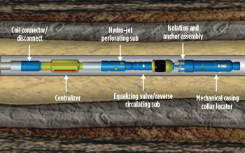
Hydra-jet perf-and-frac systems using packers. The CT downhole assembly in these systems includes a packer, as well as hydra-jet perforating nozzles, Fig. 3. The packer is set mechanically with the CT, followed by abrasive perforating through the nozzles. The annulus is usually open with a small backpressure during perforation, allowing the fluid to circulate out of the well. Fracturing is done by injection through the annulus, while maintaining the nozzles open by injecting through the CT at a very low rate (usually about 0.25 bbl/min). After the frac job, the well is shut in for a brief period, the packer is released and moved uphole to its next target and the perf-and-frac process is repeated until all the intended targets are fractured. The time lag between adjacent frac stages is usually short—20–30 min.
 |
| Fig. 3. Tool configuration for a hydra-jet perforating and fracturing system with packer. Courtesy of NCS Energy Services. |
|
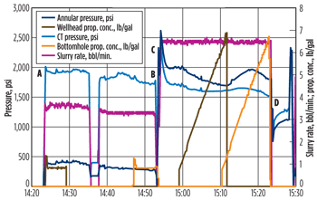
Figure 4 shows a typical frac job with this system. Points A and B indicate the start and end of the perforation process, and points C and D denote the start and end of fracturing. The pressure drop at point D indicates the perforation friction process. Note the relatively low injection rate used during this job (which also had a good increase in production).
 |
| Fig. 4. Typical frac job with a hydra-jet perf-and-frac system using downhole packers. |
|
Advantages of this fracturing system include positive isolation between stages, secured by setting the packer; ability to circulate the well clean of proppant, in case of a screen-out; and relatively rapid execution.
Possible concerns with this system can include:
Inadequate perforations. Actual field data occasionally show higher than expected perforation friction pressure. The remedy is relatively simple—longer perforating time.
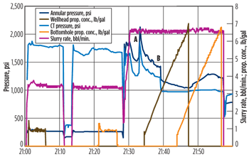
Trapped abrasive proppant. In some field cases, the abrasive proppant is not circulated completely out of the hole before the start of the main treatment. The rationale is to use this proppant as scour sand during the main treatment. However, the sand remaining in the horizontal well can settle and accumulate at the bottom of the CT-casing annulus, reducing the annular area open to flow. The reduced flow area causes increases in friction and surface pressure. During the frac job, the injected pad fluid can slowly move the plug toward the perforations, where it can cause a further sudden increase in pressure if it covers and blocks some perforations. When the plug is displaced inside the fracture, the CT pressure shows a sudden drop in pressure. Figure 5 shows an example of this situation. Point A shows the point where sand plug has covered some of the perforations. Point B shows removal of the plug as this sand is quickly displaced inside the fracture.
 |
| Fig. 5. Pressure spikes caused by sand plugs in the annulus. |
|
Another interesting feature of these treatments is that screen-outs, when they occur, appear to be very near or at the wellbore (very sharp and sudden pressure increase). However, this system allows the proppant to be quickly cleaned out and operations resumed as planned.
Concluding remarks. Dual-injection systems offer an attractive option for frac treatments that need higher sand concentrations, but not very high rates. As such, they are more popular in shallow to moderately deep oil wells, although they have been successfully used for gas wells, too. Their other advantages are versatility, flexibility, speedy operational sequences, and ability to read bottomhole pressure via the dead string. 
LITERATURE CITED
1. Surjaatmadja, J. B., East, L. E., Luna, J. B. and J. O. E. Hernandez, “An effective hydrajet-fracturing implementation using coiled tubing and annular stimulation fluid delivery,” SPE 94098 presented at the SPE/ICoTA Coiled Tubing Conference and Exhibition, The Woodlands, Texas, April 12–13, 2005.
THE AUTHOR
|
| ALI DANESHY is President of Daneshy Consultants International and an adjunct professor of chemical engineering at the University of Houston, where he teaches a graduate-level course on hydraulic fracturing. Dr. Daneshy provides consulting and training services on unconventional oil and gas completions. / alidaneshy@daneshy.com |
|


