ANDY HATCH, NICOL SHEPHERD and PETER DIEPEVEEN, E.ON Ruhrgas;
and GRANT AFFLECK, Weatherford International Ltd.
 |
|
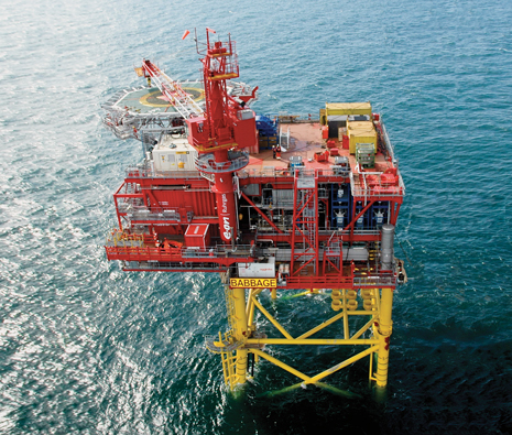
E.ON Ruhrgas-operated Babbage field began first-phase production in August 2010 following a successful three-well drilling program.
|
|
Working in close collaboration with the service company, E.ON successfully introduced broadband communications into the downhole environment in its North Sea operations. Using wired drill pipe with Weatherford’s rotary-steerable and logging-while-drilling (LWD) systems in a controlled, managed process, the operator achieved dramatic improvements in drilling performance and economics in a three-well horizontal drilling program in Babbage field. Wells were successfully geosteered to deliver sweet spots and assure optimal fracture placement while rate of penetration (ROP) was optimized. In a well-to-well comparison, ROP increased 200% and net-to-gross sand footage increased almost 100%.
BABBAGE FIELD CHALLENGES
Babbage field, located in the southern sector of the North Sea, was discovered in the late 1980s. E.ON Ruhrgas, as a field operator for the first time on the UK continental shelf, drilled the appraisal well in 2006, along with partners Dana Petroleum and Centrica. Seismic data highlighted tthe fact that the reservoir was structurally challenging. The main producing targets are located within the Leman sandstone formation; there are five major zones in the reservoir, with the “C” layer in the middle being the main target, Fig. 1. The field is internally partitioned by a series of northeast–southwest trending fault blocks that have created tightly fault-sealed compartments, each of which requires long horizontal drains to ensure maximum economic recovery.
The first-phase development plan called for three horizontal wells to be drilled according to a “single-visit” philosophy, with the wells pre-drilled, then suspended until the platform was moved into place. Placement was to be optimized to ensure the best value from the rig and, when the platform was eventually installed, to ensure high initial gas rates and rapid return on investment. Well placement was designed to yield maximum net sand footage—ideally, a 3,000-ft horizontal section in the reservoir with 2,000 ft of that within the main C1 and C2 zones. The operator had determined that the most economical production solution was four hydraulic fractures at approximately 800-ft spacing along the 3,000-ft lateral, for maximized recovery, Fig. 2.
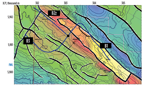
The wells were to be centrally located between the faults and targeted on structural highs where the base of the reservoir is above the free water level, to avoid fracturing into the water leg. The first well, B1, would be placed in the northwest section of the Leman C sandstone, with the second well, B2z, to the southeast and the B3 well trending to the northwest but stepped out into a different fault block, Fig. 3.
With the dispersed nature of the support team, there was no single “war room.” Instead, a secure website allowed all team members to have access to all the data from their own home bases. The dip-picking specialists, wellsite group and geosteering team were in constant contact with one another.
.jpg) |
|
Fig. 1. Logs from discovery and appraisal wells.
|
|
INTRODUCING WIRED DRILL PIPE
Initially, the plan was to drill all three wells using conventional mud-pulse telemetry. The Babbage field Phase 1 development plan was already in the advanced stages of pre-planning when members of the E.ON Ruhrgas drilling team attended a presentation of wired drill pipe during the 2009 SPE/IADC Drilling Conference and Exhibition in Amsterdam. The drilling team was inspired by the presentation to investigate wired drill pipe as a way to maximize drilling performance and economics in the new project. E.ON formed a multi-company resource team consisting of its Babbage drilling and subsurface groups, directional drilling and MWD/LWD service partner, and the wired drill pipe manufacturer. The team determined that the new technology had the potential to improve real-time understanding of the reservoir, which could help optimize well placement. The team also decided to take a controlled, managed approach to the technology introduction, waiting until the second well to introduce wired drill pipe and allowing the initial well to be drilled as planned and used as a benchmark for subsequent wells.
Wired drill pipe is the product of a US Department of Energy/industry joint project that was begun in the late 1990s to enable faster transmission of data from the wellbore to the surface than is possible using standard mud pulse telemetry. The wired drill pipe system allows bi-directional control of information at transmission rates up to 57,000 bits per second (bps), but as yet there is no capability to run power through the drillstring to the downhole tools.
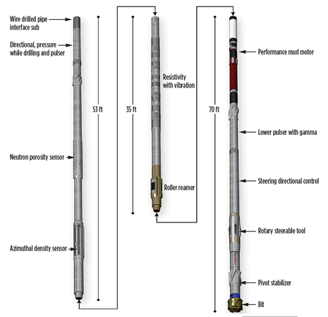
The bottomhole assembly design for the Babbage wells incorporated a triple-combo suite of LWD sensors (azimuthal gamma ray, resistivity, and azimuthal density and neutron), along with directional, bore and annular pressure sensors, vibration MWD sensors, and a Revolution rotary-steerable system (RSS), Fig. 4. To connect the wired drill pipe with the downhole network, Weatherford developed an interface sub to give the wired drill pipe access to all the data coming from downhole so that it could be transmitted to surface.
MANAGING DATA
A primary concern for the Babbage project was how to manage the volume of data that would be transmitted to surface using wired drill pipe. The resource team realized early on that the ability of the LWD surface system to manage this data would be crucial to the success of the operation. In conventional operations, the surface system receives a steady trickle of data in real time and a complete memory read on a run-by-run basis. When attached to wired drill pipe, however, the system receives a large volume of data every second and can become bottlenecked.
 |
|
Fig. 3. Relative well positions in the top Leman sandstone.
|
|
 |
|
Fig. 4. Babbage field drilling BHA.
|
|
To address this challenge, the team met regularly to plan, engineer solutions and report progress in an open and collaborative manner. Included in the collaboration was a substantial amount of pre-deployment time devoted to ensuring that the surface systems could use the data as soon as it arrived from downhole, as well as a commitment to test in advance any testable items.
Among results of the close collaboration was the development of a data simulator that would transmit data at 2,500 bps to the surface software. Additionally, programming routines were altered to handle and process the data effectively.
The BHA was also modified. A mud motor power section was added to the RSS, and the motorized RSS was taken off the downhole bus and equipped with its own newly designed pulser to send data to the surface. The LWD system also retained its own pulser to provide back-up communication in the event of a breakdown in the wired pipe network.
B1 BENCHMARK WELL
The Babbage B1 well was drilled as originally planned, with a non-motorized RSS and without wired drill pipe due to the late date of the proposed change to wired drill pipe. The primary method of geosteering was to use the vertical 48/2-2 discovery well and the vertical 48/2a-4 appraisal well to derive a petrophysical model of the expected log responses in the horizontal wells. A constant-layer thickness model developed for true stratigraphic thickness was used to compute the apparent structural dip along the well path for successful placement of the wells within the target C1 and C2 layers.
The B1 well presented a number of surprises when compared with the appraisal well. Stronger than expected formation tendencies—including sub-seismic faults—and inclination corrections—driven by bit tendencies to trend upward in sandstone and downward in shale—created directional drilling challenges that resulted in frequent changes to the well plan and a tortuous final well path with long intervals of slow shale drilling. The penetration rate was relatively slow, at an average 19 ft/hr, and yielded a disappointing net-to-gross sand footage of 38%. Reservoir and target layer penetrations were slightly short of their objectives.
GEOSTEERING CHANGES
The lessons learned from the B1 well were used to refine the geosteering process for the second and third wells. A network of specialists in five locations was established to support geosteering operations 24 hours a day, seven days a week. With the dispersed nature of the support team, there was no single “war room.” Instead, a secure website allowed all team members to have access to all the data from their own home bases. The dip-picking specialists, wellsite group and geosteering team were in constant contact with one another. To ensure overall control, a system of calls was set up, similar to regular rig calls, such that geosteering calls occurred twice a day, with discussions from these calls summarized during the more standard rig call. This procedure led to excellent lines of communication and teamwork among the rig crew, the geosciences group and the geosteering team. The collaborative environment was a key contributor to the success of the overall project.
After the B1 well, a decision tree was created to address three classes of issues. Category 1 encompassed directional issues that could be addressed at the wellsite or by calling town if it appeared that objectives were not going to be met. This level of communication was common among the offsite geosteering monitors and the E.ON and Weatherford wellsite teams for regular discussion on data and trends and to confirm structural and stratigraphic interpretations. Category 2 communications addressed geological events where the data were observed to diverge from the pre-drilled or ongoing modified model and minor changes to the well plan could be made at the wellsite to meet objectives. Category 3 communications involved major changes to the geological model where large-scale alterations to the well path would be required to address facies, major changes in structural dips, and cross-sub-seismic faults. In these cases, the team would come together to revise or create new models, communicate revised objectives, and execute new plans.
SECOND AND THIRD WELLS
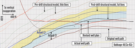
The use of wired drill pipe ensured that the objectives for wells B2z and B3 were met. While drilling out B2z to land in the top of the reservoir, the team realized that the structure was 45 ft shallow to the top of the Leman sand. The model was altered in real time, and the well trajectory was altered accordingly, to ensure landing the well in the intended reservoir section. Without the information to change the model and the trajectory, the well would have landed in shale in the C3 layer. With the changes, over 2,000 ft of the targeted C1/C2 layer was delivered at an average drilling ROP of 54 ft/hr, and net-to-gross sand footage was 70%, Fig. 5.
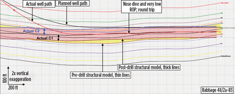
After learning that the B2z well was coming in 45 ft high, the multi-company geosteering team decided to increase the build rate on the B3 well to hit the reservoir sooner and allow more room for flexibility in the event that the reservoir was off prognosis. As drilling continued, it was noted that the B3 was only 10 ft lower than prognosis, and the well path was adjusted accordingly. Post-well analysis of the 3,047-ft reservoir section yielded an outstanding match to the prediction from seismic. Net-to-gross sand footage was 84%, total footage in the C1/C2 layer was 2,464 ft, and average ROP was 63 ft/hr, Fig. 6.
 |
|
Fig. 5. Well B2z geosteering decisions.
|
|
 |
|
Fig. 6. B3 well path and structural model.
|
|
CONCLUSIONS
The dramatic improvement in ROP from B1 to B2z and B3 was due at least in part to the enhanced drilling BHA, with a motorized RSS that increased bit rotational speed without compromising steerability. However, the mud motor could be deployed only because using wired drill pipe increased understanding of and confidence in reservoir data.
The Babbage Phase 1 development project illustrated that the introduction of new technology can have far-reaching implications beyond the technology itself. In this case, the introduction was undertaken in such a way that substantial dialog occurred between all the stakeholders in the project, and the dialog was as important as any of the specific technology introductions. Additionally, by introducing one technology, it then became possible to introduce another that, although not directly linked to the first, was interdependent with it. Recognizing and using these synergies will enable and encourage E.ON Ruhrgas to continue to adopt new technologies going forward. 
ACKNOWLEDGMENT
This article was prepared in part from SPE/IADC 140391 presented at the SPE/IADC Drilling Conference and Exhibition held in Amsterdam, March 1–3, 2011.
|
THE AUTHORS
|
| ANDY HATCH is a chartered engineer with 30 years of upstream oil and gas experience, predominantly in the North Sea. He is the UKCS Drilling Manager for E.ON Ruhrgas, having previously worked for BP, Arco and Schlumberger. |
|
| NICOL SHEPHERD is a Drilling Team Leader for E.ON Ruhrgas UK E&P, having joined the company in 2007 after holding engineering roles in Shell and BJ Services. He earned a bachelor’s degree in engineering from the Robert Gordon University in 1997. |
|
| |
| PETER DIEPEVEEN is a Subsurface Team Leader for E.ON Ruhrgas UK E&P, having joined the company as a geology consultant when it acquired Caledonia Oil & Gas in 2005. He earned a master’s degree in geology at the University of Leiden in 1981. |
|
| GRANT W. AFFLECK is the Global Business Development Manager for Weatherford Drilling Services, having previously worked with the company’s UK Drilling Services group as Operations Manager and as Regional Manager for the North Sea and sub-Saharan Africa. He earned a degree in geology from the University of Edinburgh in 1988. |
|


.jpg)
.jpg)


