What’s new in artificial lift
Part 1—Introducing developments in natural gas well dewatering.
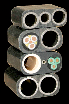
Part 1—Introducing developments in natural gas well dewatering.James F. Lea, PL Tech LLC; and Herald W. Winkler, Texas Tech University Gas well deliquification is required when the gas rate drops below a critical rate or velocity that allows excess liquids to accumulate in the flow passage, hindering gas production. Many techniques are used to mitigate this condition, including velocity strings, surfactants, various types of pumps and gas lift, among others. Among the recent developments in gas well dewatering presented in this article, one company provides umbilicals of various construction to more easily allow use of hydraulically or electrically powered pumps. Five hydraulic pumps, two electrical pumps and four surface units are discussed, as well as a single-point gas lift system. Also discussed is an improvement to the critical velocity reducer (CVR) concept, which dewaters long perforated intervals using a dead string combined with surfactants. The improved design allows installation with snubbing. Finally, a calculation sheet and online program is discussed that assists in selecting the best technique for dewatering gas wells. COILED TUBING CONVEYANCE CJS Coiled Tubing Supply Ltd. has developed a coiled tubing (CT) technology that enables the conveyance of many deliquification systems. Originally developed to increase the efficiency of deploying a hydraulic submersible pump (HSP), FLATpak encapsulates multiple CT strings or electrical conduits of different sizes in a high-strength thermoplastic jacket, Fig. 1. The final umbilical package is configured in a rectangular matrix that can be deployed by a conventional shallow CT unit equipped with modified strippers and injector chains. Using a specialized hanger and wellhead system, the umbilical package can easily by integrated into existing oil and gas wells for permanent installation. The package has demonstrated exceptional resilience to damage following multiple runs.
Combining all strings into a uniform body greatly reduces the cost of deploying a dewatering system that requires multiple strings, allowing the use of artificial lift technologies that were previously economically unviable for North American well operators. To date, about 250,000 ft of the umbilical package has been manufactured to support the conveyance of artificial lift systems. Configurations of the umbilical package have been developed for a wide variety of artificial lift systems, including some discussed in this article. CJS has also partnered with Source Rock Energy to develop a non-invasive cleanout technology using a jet pump conveyed on the umbilical package. This deliquification solution has demonstrated exceptional results in field testing, with low-pressure vertical and horizontal wells showing immediate increased gas production, eliminating the initial production loss resulting from conventional cleanout technology. This service application meets the demands of the many North American wells that require deliquification but cannot economically justify a permanent artificial lift installation. HYDRAULIC PUMPS Five advancements in hydraulic pumps are introduced, including positive displacement pumps, a diaphragm pump, and a jet pump system. CT-conveyed hydraulic pumps. Cormorant Engineering, formed in 2009, is developing and marketing two hydraulic systems for dewatering gas wells: one deployed through tubing and one deployed through casing, Fig. 2.
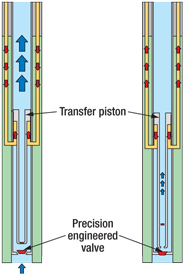
In the through-tubing (TT) system, the hydraulic pump is run on CT through the production tubing and is seated in a seating nipple at the bottom of the tubing. The CT is filled with hydraulic fluid to operate the pump. Water is pumped up the CT-tubing annulus, allowing gas to flow up the tubing-casing annulus. In the through-casing system, the hydraulic pump is run on a FLATpak umbilical package composed of two CT strings. One CT string is filled with hydraulic fluid, and water is pumped up the other CT string, allowing gas to flow up the umbilical package-casing annulus. The hydraulic power unit (HPU) at the surface applies hydraulic pressure to the downhole pump, pushing the power piston up. The HPU then releases the hydraulic pressure and allows the hydraulic fluid to drain back to the tank. The difference in fluid density between the pumped water and the hydraulic fluid provides the restoring force that pushes the power piston down. Cormorant has developed a dynamic finite-element model that simulates the performance of these dewatering systems and facilitates system optimization for each well. The model results have been validated by comparison with measured data from a test well and from actual gas well installations. As of January 2010, four of these systems had been manufactured and installed. One is a 2⅜-in. TT pump installed in a test well. This pump has undergone extensive testing and is used as an engineering test bed for design of seals and other components. It is running continuously to demonstrate the longevity of the pump and the HPU. A 2⅜-in. TC system is running in a horizontal coalbed methane well at 2,800 ft with an 86° inclination. The third and fourth systems are 3½-in. TC pumps in 7,000-ft conventional gas wells. Another hydraulic pumping system designed for CT conveyance is Cyclone Production Tools’ Perry Pump, a positive displacement pump that uses a water-based power fluid in a triple 1-in. CT package. The surface unit supplies hydraulic pressure (powered by propane, natural gas, or an electric power unit) for the upstroke and downstroke by alternating the power fluid between the two outer CT strings. Produced fluids are pumped to surface up the center string at the desired rate. The surface unit’s small footprint and quiet operation make it attractive for residential settings. Hydraulic piston pump. The Hygr Fluid System from Hydro Pacific Pumps is a surface-powered downhole pumping technology that uses a downhole transfer piston with specific hydraulic principles to supply theoretical pump efficiencies in excess of 95% for wells as deep as 3,000 ft and producing 20 to 200 bpd. When used to dewater very low-producing gas wells, the system requires minimal horsepower, and its low capital and operating costs have the potential to return many marginal wells to profitability. The pump’s working components are a hollow piston and two spherical valves. Since there are only three working parts, and they cycle at a slower rate than most piston pumps (3 to 30 cycles/min.), maintenance requirements are substantially reduced. The piston has three zones: the hydraulic drive side, the product fluid side and the intake fluid side, Fig. 3. Within the piston, the power fluid is hydraulically separate from both the product fluid and the intake fluid, to prevent gas locking.
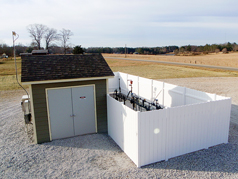
Unlike other pumping systems, the Hygr system requires only one hydraulic power fluid line down to the pump instead of two. The result of this single coaxial system is a considerable decrease in setting, material and maintenance costs. The control unit allows pumping rates as low as a single stroke per minute, or less if required, making the unit very efficient for low-volume applications. The current design, released for testing and sales in Canada and the US, has a 3½-in. OD with an 18-in. transfer piston configuration that produces between 1 bpd and 35 bpd of fluids. The original concept pump was deployed in a 1,600-ft oil well in Oklahoma; based on the resulting data, extensive bench testing was conducted on production units. In 2008, one unit was tested for three months in a shallow water well. Another unit has been operating since early October 2009, 24 hours per day, at a rate of 30 bpd in a water well with a simulated pumping level of 1,500 ft. Hydro Pacific has also designed, built and bench tested a 1½-in.-OD unit for pumping 3–5 bpd. Results have been positive, and new units in 1½-in. and 2-in. sizes are being developed. Also, in response to industry requests for a unit with greater pumping capacity, the company is reviewing a 4½-in.-OD unit that pumps 200 bpd or more in vertical, angled and horizontal configurations. Hydraulic diaphragm pump. El Paso E&P Company recently implemented a new artificial lift method from Smith Lift for its coalbed methane operations in the Black Warrior Basin. The hydraulic diaphragm insertable (HDI) pump and low-profile surface unit—designed for CBM wells and other shallow, low-liquid-rate wells—allowed El Paso to minimize surface disruption, improve safety and reduce noise in residential areas and farms. The new method build’s on Smith Lift’s established hydraulic diaphragm ESP technology, but eliminates the downhole electric motor and electric line to surface, for reduced maintenance. The surface unit is only 4 ft by 4 ft by 3 ft and may be enclosed to blend in with the environment, Fig. 4. It has no large moving parts and features a quiet three-phase, 480-volt electric motor that powers a surface pump. The surface pump circulates working fluid through an engineered thermoplastic hose connected to a downhole HDI pump. The hose is also used to convey the HDI pump into the production tubing.
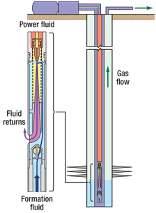
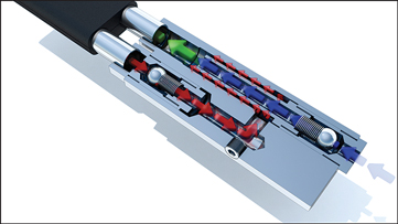
Celeste Hagler, an El Paso senior production engineer who has been working in the Black Warrior Basin for 20 years, reports that the new method has allowed El Paso to work more productively with landowners to minimize disruption to their surroundings. One area farmer said, “This new system makes it a lot easier for me to work my land, and I’m happy with the improvements El Paso has made.” Jet pump. J&J Technical Services has developed a jet pump design for dewatering mature gas wells, conventional horizontal gas wells, CBM and shale gas wells, as well as for producing oil from vertical and horizontal wells. Among the advantages of jet pumping, it requires no downhole moving parts, it is not affected by hole angle or “corkscrew,” it will not gas lock, and it is able to lift sand. The new pumping system has been successfully deployed in oil and gas wells in Western Canada and the US for permanent pumping installations. The jet pump utilizes the Venturi effect to pull wellbore fluids into a flow stream that is pumped downhole and back up again through a dual CT string or a tubing-annular configuration, Fig. 5. In either case, the key components of the jet pump assembly are flow-reversible and, therefore, do not require a service rig intervention to be retrieved, inspected, serviced or changed. Pump component change-outs are one-man operations that require only one to two hours to perform. Coupled with dual-string CT technology, the jet pump can be run in hole or retrieved with a single CT unit operation.
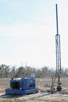
The improved jet pump design uses larger fluid input areas and cleaner flow geometries, allowing operation with efficiencies equivalent to or greater than conventional artificial lift systems. These features also facilitate the movement of solids through the jet pump, making it a good option for high-solids-production environments. Jet pump installations require surface pumping equipment, and, in the case of J&J Tech’s new jet pump, high-pressure diaphragm pumps are being used as surface equipment, greatly reducing environmental and maintenance issues traditionally associated with plunger-type pumps. These units are closed systems with cartridge-type check valves and diaphragms for ease of maintenance and lower operating costs. In addition to the surface diaphragm pump, a systems approach is used to facilitate the surface fluid handling needs. Units are configured with natural gas engines or electric motors with variable-frequency drives (VFDs) to reduce operating costs and pump wear. ELECTRICAL SUBMERSIBLE PUMPS Two ESP advancements are presented: an electrical submersible twin-screw pump and a small electrical submersible progressive cavity pump. Twin-screw ESP. Can-K has developed a twin-screw downhole electrical pump that has a number of potential advantages over traditional ESPs. The electric submersible twin-screw pump (ESTSP) is a positive displacement pump, unlike traditional ESPs, so pressures remain the same with varying speed. Speed is the only adjustable parameter, and it can be changed to alter the pump rate while keeping pressure constant. An additional advantage in using the ESTSP is that there is no up or down thrust. The design also incorporates patent-pending balancing pistons, and it does not distinguish between gas and liquid because it only interprets volume, so it can handle very high gas intake conditions. Unlike a centrifugal pump, the twin-screw unit has no best efficiency point, and it can draw down to 0 psig (vacuum conditions). A high-powered motor is used so the pump can be run at higher maximum speed. It is always recommended to ensure that at least about 3% of the flow by volume is liquid, to keep the motor cool. In a sour well, all the gas can be moved through the pump if required, provided a large enough pump with sufficient horsepower is used. Field applications have confirmed the pump’s usefulness in wells with high asphaltene content because asphaltene will not break out due to minimal to nil shear, and the higher viscosity created by any residual asphaltene actually increases pump efficiency. Horsepower savings have also been observed. Recently, the pump has been tested for dewatering CBM wells. In a high-gas application, the ESTSP did not heat the motor as much as a conventional ESP—perhaps because mist forms on the motor as the gas is continuously pumped. The temperature rise was only a few degrees even when moving about 96% gas volume. Further studies are ongoing to understand this phenomenon. The twin-screw pump also comes in top-drive and rigless top-drive versions. Submersible PCP. Enhanced Recovery Services Inc. of Canada and Lorentz Pumps of Germany have been working together for the past four years to develop a unique, cost-effective artificial lift package to address some of the problems associated with dewatering shallow gas wells. The central component of the dewatering package is a small electrical submersible progressive cavity pump (ESPCP) system that includes a submersible motor, a small PCP, and a surface pump controller. The brushless, water-filled, submersible DC motor has a 3½-in. OD, which allows adequate clearance inside the 4½-in. casing that is frequently used as production casing for shallow gas wells. The motor driving the PCP is powered by a unique pump controller that accepts DC current from solar, wind or thermal electric generation (TEG) when the pump has to be deployed at remote (non-electrified) sites. When AC power is available, an AC/DC converter is provided that converts either 115-VAC or 230-VAC (single-phase) power to 150–200 VDC to operate the pump controller. The pump controller automatically “soft starts” the motor by using PWM power to ensure maximum starting torque, then quickly ramps up the pump speed without the need for a downhole mechanical torque arrestor. Pump-off control is available by use of downhole or surface sensors or motor current sensing software. The controller can be programed to re-start the pump automatically after delay intervals of 20–720 min. The pump system has typical power requirements ranging from 400 to 1,000 watts for pumping fluids from depths of about 1,000–2,300 ft at rates of 0.8–1.6 gal/min. All motor and pump components that come in contact with formation fluids are made of 316 stainless steel. The entire pump and motor assembly is about 28 in. long and weighs 25 lb. The pump and motor assembly are installed by means of an umbilical system and coiled tubing unit. The umbilical is composed of a circular bundled package including a central ½-in. stainless steel tubing for fluid production and power and sensor cables, all enclosed in a thermoplastic sheath. This package allows the pump to be installed rapidly under live well conditions by using a simple hydraulic BOP on the wellhead. SURFACE UNITS Four innovative surface pumping systems are presented: two hydraulically powered surface pump jacks, a solar-powered pumping unit, and a pumping system using a cable in place of rods. Hydraulic surface units. Louisiana-based Petro Hydraulic Lift Systems (PHL) has developed an innovative hydraulic surface pump for use with conventional downhole rod pumping equipment. With more than four years of applications and no rod failures, the system has been confirmed as a viable alternative for artificially lifting oil to the surface and for gas well deliquification. Unlike traditional horsehead pumps for rod pumping, the hydraulic system can instantaneously fine tune the pumping rate of its equipment to match the feed rate of the well without the use of pump‐off controllers or other start-stop devices. The equipment is currently able to achieve stroke rates from 0.5 to 4.0 strokes/min.—rates not achievable by conventional horsehead pumps—at well depths to 13,000 ft. The long, electronically paced vertical stroke results in reduced rod and tubing wear and increased production efficiency compared to conventional pumps, Fig. 6. Furthermore, due to its flexibility, the PHL system can be used to pump oil one month and subsequently to de‐water a natural gas well the next.
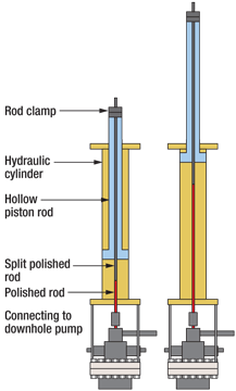
The pump jack is available in versions with a 96‐in. stroke (for CBM applications) and a 144‐in. stroke (for deeper applications). Natural gas/propane, diesel or electrical power units are available. Site conditions allowing, the equipment can be installed and working within 2 hr. Another hydraulic surface pumping system for gas well dewatering is from ICI Artificial Lift of Lloydminster, Alberta, whose surface pumping units have been used to pump off several wells where a conventional beam jack had been unsuccessful. ICI offers two rod-pumping hydraulic jacks for dewatering. The Copperhead 10 Series has a 14,000-lb lift capacity and a 64-in. stroke designed for the production of shallow gas and CBM, as well as light-production oil wells. It replaces the conventional rod and beam as well as plunger lifts and velocity strings on wells with increased fluid volumes. The Golden Rod 20 Series has a 30,000-lb lift capacity and a 120-in. or 144-in. stroke. In both series, a split polished rod connects to the top of the rod string, then runs through a patented hollow piston rod and attaches to the top of the hydraulic cylinder with a rod clamp. The hydraulic cylinder reciprocates the hollow piston rod, and with it the rod string, providing the required reciprocating action to the downhole pump, Fig. 7.
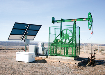
ICI is currently working on modifying a pump‐off controller and building in logic surrounding the shape of a dynocard, in order to fully automate the well by having the surface equipment speed change to match the demands of the downhole pump. Solar-adaptable pump. A fiberglass rod pumping system has been designed for producing low volumes of fluid from liquid-loaded gas wells, using an efficient pumping unit operating on a 0.5-hp to 3-hp, solar-powered electric motor, Fig. 8. The Low-Volume Pumping System (LVPS) incorporating the Eco2 pumping unit is designed specifically for pumping wells that produce less than 20 bpd. A small-diameter insert-type rod pump is used so that pump changes require only the use of a spooling trailer, not a workover rig.
Other than using solar power, this system is installed in two other configurations: a hybrid system using available electricity and a conventional beam pumping unit. In any configuration, the goal is to minimize friction losses, so a small motor can power the system. A small-diameter plunger limits both the fluid load lifted by the rods and the amount of fluid volume that can be produced to the surface, but even within those limits the system is economic for many dewatering applications, since only a few barrels per day of water can lead to liquid loading and kill flow from a gas well. The pumping system uses a lightweight continuous fiberglass rod string or a coupled fiberglass string to maximize efficiency of operation. Typically, a 3,200-ft well producing 10 bpd of water will require less than 1 hp to run the pumping unit. The system has been used successfully at depths up to 5,800 ft. Cable pumping system. Vann Pumping Systems has developed a cable-operated system designed as an alternative to conventional rod-and-jack methods. Instead of rods to convey the up- and downstroke of the downhole pump, a single cable is used. A 700-lb weight made up of sinker bars attaches to the pull rod of the downhole pump and the cable, causing the cable to remain in tension during the downstroke. The tower pumping unit is a computerized hydraulic lifting system that may be installed on any well that uses a downhole reciprocating pump. The cable pumping method offers many options and advantages that conventional rod pumping does not offer. The size of the unit and the length of stroke can vary with the depth of the well, and longer strokes are possible than with rod pumping. Strokes per minute can be regulated to match production coming into the well. No workover unit is needed to run or retrieve the downhole pump. The system can be pulled by a special cable truck for any repairs needed. The equipment is designed to operate safely with no exposed moving parts on the surface equipment, which has a reduced footprint compared with traditional pump jacks. OTHER DEVELOPMENTS Two gas lift applications to relieve liquid loading are presented, as well as an online tool for selecting dewatering technologies. Single-point gas lift. A new version of the existing Cyclone product line has been adapted to take advantage of the FLATpak umbilical CT system and to enhance effectiveness of wellhead compression used for artificial lift. The VLift tool is a closed-loop, single-point gas lift system with minimal rate required for maintaining critical velocity. Deployment via the umbilical system minimizes friction pressure and reduces the required injection rate to maximize lift performance. The tool has few moving parts. One check valve on the gas injection side prevents wellbore fluids from entering the injection string, while another, located on the bottom of the production string, is inverted to keep fluid trapped in the production tubing until the proper injection rate is achieved and the fluid is lifted to surface, Fig. 9. Once the hydrostatic fluid column has been removed, a pressure differential is created as gas passes around the patented choke sleeve. This pressure differential allows the production string check valve to open, and critical velocity is then maintained by the surface compressor, causing any fluids and/or solids entering the production tubing to be carried to the surface with the gas stream.
Critical velocity reduction improvement. Weatherford has improved its patented Critical Velocity Reducer (CVR) concept by redesigning it to allow for complete snubbing installations of the entire assembly. In the original CVR, introduced in 2007 for gas wells with extended perforated intervals, area reduction provided by dead string installed down through the perforation interval reduces the gas volume required to keep the well unloaded. Foamer injection can be added to further reduce surface tension and density, and plunger lift can be initiated from the top of the heavy-duty flow sub to take the well further down the type curve or to its economic limit. As the number of installations grew, it became apparent that the major disadvantage of the original design was the inability to snub the system into the ground due to the externally banded capillary injection tubing. Operators were installing the CVR system on the first tubing completion often directly after frac and flowback operations, and killing the well to install the tubing may have had a negative effect on reservoir deliverability. The iCVR was introduced specifically to eliminate this problem, Fig. 10. In the improved system, the production tubing and dead string are snubbed in using a removable plug on the bottom of the dead string, and the isolation sleeve is installed inside the heavy-duty flow sub. Once the production tubing is landed and the pump-off plug and isolation sleeve are removed, the capillary injection string can be snubbed in under pressure as well.
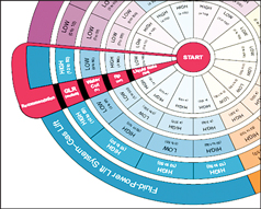
Due to the inherent tensile strength limitations and lack of forcible workability of capillary injection tubing, a two-trip system design was necessary to ensure that the installation could be pulled with minimal effort and maximum reliability. The result was a unique cap-connect assembly consisting of two sections. The lower section consists of the plug body, the capillary injection tubing and the injection valve. This entire assembly is installed on slickline and lands in the nipple profile below the heavy-duty flow sub in the production tubing. The capillary injection tubing is hung off the bottom of the plug body down to the differential injection valve. The upper section of the cap-connect assembly consists of the prong body, the double grip system and the capillary equalization assembly. The double grip system uses the internal capillary injection pressure to hold the prong in place during operation. The equalization design allows the pressures to be equalized at the plug body to allow the assembly to be pulled with minimal pull weight—far less than the minimum yield of the capillary tubing—with no fear of trapped pressure below the plug body inside the dead string. At surface, the capillary injection tubing is hung off from a conventional capillary injection hanger from the top of the wellhead. Plunger lift operation is not possible with the iCVR system due to the internally installed capillary injection string. The improved system allows capillary injection tubing to pulled independently of the production tubing. No wellhead modifications are required for installation, no bands or heavy-duty clamps are required to secure the capillary tubing, and the system is not affected by downhole deviation. Digital unloading selector. Weatherford’s unloading selector, a logical artificial lift selection process for gas well deliquification that had previously only been available in a print version, is now online at www.weatherford.com/unloader. The unloading selector works by assigning a high or low value to each of four readily available surface-gathered data points: liquid rate, flowing tubing pressure, water cut percentage and gas liquid ratio, Fig. 11.
The online version is user interactive to provide more information on the selected type of lift. Other features include selection options in both metric and standard, a gas-liquid ratio calculator, and user log-in with last-selection memory for further review of data. Also, after a deliquification selection is made, the user may receive a copy of the selection by email. Well information entered into an electronic data sheet during the selection process can be sent directly to a lift expert to review and provide a technical evaluation and cost proposal. ACKNOWLEDGMENT The authors thank the featured companies for providing the information for this article. The authors are not responsible for claims made by the manufacturers and vendors about their products’ capabilities..
|
|||||||||||||||||||||||||||||||||||||||||||||
- What's new in production (February 2024)
- Prices and governmental policies combine to stymie Canadian upstream growth (February 2024)
- U.S. operators reduce activity as crude prices plunge (February 2024)
- U.S. producing gas wells increase despite low prices (February 2024)
- U.S. drilling: More of the same expected (February 2024)
- U.S. oil and natural gas production hits record highs (February 2024)
- Applying ultra-deep LWD resistivity technology successfully in a SAGD operation (May 2019)
- Adoption of wireless intelligent completions advances (May 2019)
- Majors double down as takeaway crunch eases (April 2019)
- What’s new in well logging and formation evaluation (April 2019)
- Qualification of a 20,000-psi subsea BOP: A collaborative approach (February 2019)
- ConocoPhillips’ Greg Leveille sees rapid trajectory of technical advancement continuing (February 2019)

