Studies show the importance of an integrated design approach for a deep-draft semisubmersible and subsea wells tied back with steel catenary risers.
Kevin Haverty, Tao Wang, Yan Zhou, Jack Zeng and Magne Nygård, Aker Solutions
The semisubmersible has been a workhorse of the offshore oil and gas industry for decades, and has served in multiple applications including as a mobile offshore drilling unit (MODU), as a multi-service vessel (MSV) and as a floating production unit (FPU). By far the most common application has been as a MODU. The first purpose-built drilling semisubmersible was the Ocean Driller in 1963. As of December 2009, there were 168 semisubmersible drilling vessels available for deployment worldwide in various water depths ranging from hundreds of feet to in excess of 10,000 ft.
The first application of a semisubmersible as an FPU came in 1975, when a MODU was converted to an FPU for development of Argyll Field in the North Sea in about 250 ft of water depth. The first purpose-built semisubmersible FPU was the Balmoral FPU, which started production in 1986 in the North Sea in water depths of about 500 ft. Subsea wells were tied back to the Balmoral FPU via flexible risers. The first application of a semisubmersible FPU with subsea wells tied back via steel catenary risers (SCRs) occurred offshore Brazil in 1998. Petrobras installed a 10-in. SCR in 2,985 ft of water depth as part of the Marlim Field development in the Campos Basin, where environmental conditions can be described as moderate.
In the Gulf of Mexico, there are currently six semisubmersible FPUs in operation and a number of others in the planning phases. All six working semisubmersible FPUs are located in water depths ranging from 6,000 ft to 8,000 ft, and each has wells tied back via SCRs in addition to export SCRs. Evidently, the choice of a semisubmersible with SCRs is a well-proven concept for ultra-deep waters in the GOM. But what about applications in the 3,000–6,000-ft water depth range? The objective of this article is to examine the significant design drivers for a semi-SCR-based field development option in this water depth range and to present cost-effective solutions thereto.
DEEP DRAFT SEMISUBMERSIBLE
It is instructive to take a step back a decade or more to when operators first started examining the option of using a semisubmersible as a field development option. Design input was often limited to just a payload estimate and some constraints on vessel accelerations for topsides equipment design for a given site in the GOM. In many cases, these preliminary designs were submitted in response to a request for quotation (RFQ) from operators as part of a concept selection phase for a particular field development. Operators would typically engage the services of riser engineering firms to evaluate riser responses for each of the proposed floater concepts. This approach did not utilize the full potential of the platforms, and semi designers especially began to adopt an integrated design approach wherein the host facility was designed as a system, as opposed to a set of individual components.
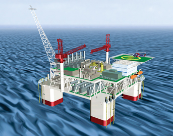
Riser performance became a key factor in the design of the motion characteristics of the semisubmersible and resulted in the development of the deep-draft semisubmersible (DDS) in use today, Fig. 1. To develop a cost-effective DDS that is feasible for SCR tieback in harsh environmental conditions, Aker Solutions, riding on its extensive experiences from more than 50 drilling and production semisubmersibles, performed a comprehensive study starting in 2001 to investigate the governing design parameters of a DDS floating system. This investigation helped to facilitate the successful design and delivery of a DDS for Chevron’s Blind Faith Field development in 2008. The key design principles developed for a DDS are:
• Emphasis on operational safety, flexibility and simplicity
• Maximization of floating system integrity, efficiency and reliability
• Design of the FPU as an integrated unit with topsides, hull, mooring and risers
• Restraint of hull motions to satisfy riser performance requirements
• Optimization of hull dimensions to allow for quayside integration of topsides with hull
• Adequate buoyancy and stability in all pre-service and in-service conditions.
 |
|
Fig. 1. Deep-draft semisubmersible.
|
|
While the major attraction of a semisubmersible FPU with SCRs lies in its simplicity, one of its principal challenges is to maintain extreme and fatigue responses in the touchdown zone of the SCRs within design limits.
The extreme response is defined in the context of how a riser responds in severe environmental conditions, such as in a hurricane, when the highest riser loads are experienced. The fatigue response discussed here refers to the rate at which fatigue damage accumulates due to various sources of cyclic loading.
Maximum stresses and fatigue damage rates occur in two distinct regions along an SCR: the touchdown region and the hangoff region. In the hangoff region, extreme and fatigue responses are controlled by inclusion of either flex joints or stress joints. In recent years, titanium stress joints have been used in the hangoff region due to increased strength, flexibility and fatigue properties of the titanium material.
Control of extreme and fatigue responses in the touchdown zone cannot so easily be controlled mechanically as in the hangoff region due to the significantly longer extent of the touchdown region. Instead, the design approach adopted is one in which sufficient compliance is introduced into the global configuration of the system such that the extreme and fatigue responses in the touchdown zone remain within target limits. In this context, the term system is meant to include the design of the hull, mooring and riser system as an integrated unit, but not the riser in isolation.
COST-EFFECTIVE DESIGN SOLUTIONS
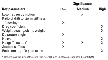
To overcome the design challenges and incorporate the design principles set forth above, a series of internal technology development studies was launched with a focus on gaining an in-depth understanding of the most significant design drivers for the DDS in GOM waters of 3,000 ft and deeper. First, the studies focused mainly on the touchdown zone (TDZ) responses, both extreme and fatigue, of SCRs in a range of water depths with the corresponding properly designed DDS hull and mooring configuration. Table 1 summarizes the relative significance of a number of design variables with regards to TDZ extreme response.
Of primary interest are those variables having high significance (i.e., potential to reduce peak stresses by 10% or more) and over which the designer has some element of control. Three design variables were identified that afforded the most significant opportunities for improvement of SCR TDZ extreme response: vessel heave, SCR hangoff location and weight tuning in the lower portion of the catenary (i.e., the riser’s sagbend region).
The most significant design variable is vessel heave. More specifically, it is the amplitude of vertical displacement and velocity at the riser hangoff location, which includes the contribution due to vessel heel. For larger semis—i.e., with topside payload in excess of 20,000 tons—the contribution to vertical motion at the riser hangoff from vessel heel can have a more noticeable impact on TDZ extreme response than for smaller semis. Thus, for larger semis, it is very beneficial to place the riser porches on the inside faces of the pontoons.
As noted in Table 1, field environment condition is a variable of high significance. Especially in the Gulf of Mexico, metocean criteria have become more severe in the past decade, and, additionally, there is substantial variation between the Western Gulf and the Eastern Gulf. While these metocean criteria can be accommodated in design of a DDS, the impact on the floating system will be reflected in the size of the system and its cost.
| TABLE 1. Cost-effective solutions to enhance SCR performance for deepwater field development |
 |
As noted earlier, one of the design principles is to allow for quaysides integration of the topsides and hull. This is one of the most beneficial features of a semisubmersible FPU, which eliminates costly offshore integration and reduces schedule risk due to adverse weather conditions offshore. For GOM applications, a typical execution scheme comprises hull fabrication at an overseas fabrication yard followed by a dry transportation to a GOM integration yard. Accordingly, current limits on quayside water depth and channel dimensions at the integration site need to be considered.
It is noteworthy that, as the hull draft is increased to reduce first-order heave motions, not only does the project cost rise, but also the project execution on quayside integration of topsides with the hull is affected. Specifically, the columns are lengthened both to increase mean draft and to maintain airgap requirements when installed in the field. Thus, when the platform is at the keyside, deck mating and installation at the integration yard involve added complexity due to the increased height of the lifts. Furthermore, additional temporary buoyancy by means of sponsons may be required to satisfy stability requirements during tow-out of the platform from the quay.
Fortunately, the internal studies found that there is no significant driver based on riser TDZ response to increase hull draft beyond that which can currently be accommodated at existing GOM facilities. Therefore, it appears that a robust DDS design, unconstrained by quayside conditions of a GOM integration yard but driven by SCR performance, can be achieved.
A third significant design parameter relates to weight tuning of the risers themselves. Aker Solutions promoted this parameter in connection with design of titanium catenary risers for potential gas export for the Åsgard-B semi in about 1,000 ft of water back in 1999. This project was not realized, but the principles were later applied successfully for SCRs.
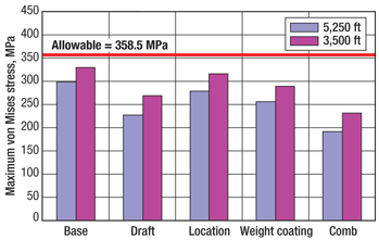
Internal studies show that increasing the submerged weight in the lower catenary section of a riser can significantly reduce maximum stresses in hurricane events. One option considered included increased insulation density in the case of wet insulated production risers and distributed weight coating in the case of bare import and export risers. Sample results are presented in Fig. 2 representing a 10-in. oil production riser with a surface shut-in pressure of 10,000 psi. Two water depths are considered: 5,250 ft and 3,500 ft.
 |
|
Fig. 2. Production riser extreme response sensitivity.
|
|
This example shows that the most effective design variable is vessel draft. Increasing the vessel draft by 20 ft resulted in reductions of 24% and 18% in maximum touchdown zone stress in water depths of 5,250 ft and 3,500 ft, respectively. In the case of the hangoff location design variable, the significance of the impact on SCR TDZ extreme response varies. However, the improvement in TDZ response by hanging the SCRs off the inside of the pontoons is not a function of platform size alone. It should be noted that low-frequency roll and pitch motion amplitudes are also dependent on metacentric height (GM), which is the distance between the semi’s center of gravity and its metacenter. Platform designs with adequate but lower in-place GM values will see a relatively larger difference (i.e., in excess of 10%) in TDZ response between designs with riser hangoffs on the outside and on the inside of the pontoons.
In addition to the response improvement realized by supporting the risers from porches on the inside of the pontoons, additional benefits can be realized during project execution. For example, one can reduce schedule risk by pre-laying risers in the field prior to installation of the platform at the site. Hookup of the risers to the platform can be performed by an onboard platform riser pull-in system, thereby eliminating the need for expensive heavy lift vessels and reducing schedule risks due to vessel availability and weather conditions.
In the sample case of adding weight in the coating of the production riser, if the insulation density over a 750-ft segment in the lower portion of the catenary (i.e., in the sagbend region) was doubled, it resulted in reductions of 14% and 12% in maximum stress in the touchdown zone in water depths of 5,250 ft and 3,500 ft, respectively.
A combination of all three design variables (hull draft, riser hangoff location and weight coating) resulted in reductions of 36% and 30% in maximum touchdown stress of the production riser in water depths of 5,250 ft and 3,500 ft, respectively.
A similar pattern to that described above was also observed for bare export and import risers. In the sample case of the bare export and import risers, additional weight was added over a segment length of about 800 ft in the lower portion of the catenary. The total additional weight was in the range of 40–60 tons. The additional weight in the riser sagbend was seen to be more beneficial in the case of light risers such as gas export risers.
With regard to fatigue damage in the touchdown zone, the three major contributors to long-term fatigue damage are 1) wind- and wave-induced first- and second-order vessel motions, 2) current-induced motions of the hull (VIM), and 3) current-induced motions of the riser (VIV). The contribution from VIV is generally mitigated by use of triple-start helical strakes on the entire suspended length of the riser. The VIV phenomenon, in general, is not dependent on the vessel characteristics.
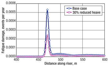
Just as in the case of SCR TDZ extreme response, increasing vessel draft also results in a reduction of fatigue damage rates from wind and wave effects. As observed in Fig. 3, a 30% reduction in heave motions resulted in a reduction of almost 60% in fatigue damage rate (i.e., more than doubling the fatigue life) in the case of a production riser in 5,250 ft.
 |
|
Fig. 3. The effect of reduced heave on long-term wave-induced fatigue damage in the TDZ of a production riser.
|
|
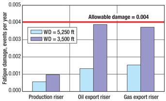
Figure 4 shows the total fatigue damage from all three major sources of fatigue for three riser types in two water depths (3,500 ft and 5,250 ft) in the GOM. In this case, the draft increase alone results in adequate fatigue lives for all three riser types, based on a field life of 25 years, in water depths of 3,500 ft. The vessel draft is well within the limits that can be accommodated at existing GOM fabrication and integration yards. Increased margins can be realized by incorporation of riser sagbend weight tuning and periodic vessel relocation, or by an additional increase in draft.
 |
|
Fig. 4. Fatigue damage variation with water depth for three riser types.
|
|
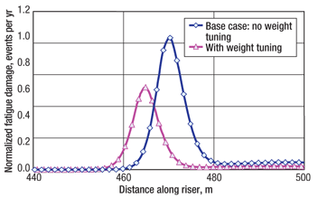
Weight tuning in the sagbend of an SCR has been successfully implemented in GOM applications. Weight tuning can be implemented by applying coatings of varying densities. As shown in Fig. 5, a 40% reduction in fatigue damage rates was observed in the case of an 8-in. production riser in 5,250 ft.
 |
|
Fig. 5. The effect of weight tuning on long-term wave fatigue damage of the TDZ of a production riser in 5,250 ft of water depth in the GOM.
|
|
Periodic vessel relocation is another very cost-effective means of reducing fatigue damage. This is especially true in the case of relatively small platforms with a limited number of risers, where platform relocations principally in the plane of the risers can be achieved. Take, for example, a 10-in. production riser in 5,250 ft of water depth. A single vessel relocation of about 100 ft midway through the life of the field (e.g., after 10 years in a field with a 20-year design life) will shift the riser nominal touchdown point and result in a 44% reduction in fatigue damage (or a 78% increase in fatigue life). If one implements two vessel relocations at equally spaced intervals over the field life, the reduction in fatigue damage would increase to 60% (equivalent to a 150% increase in fatigue life). This is an attractive feature of a semisubmersible that can be easily and cost-effectively incorporated into the design.
CONCLUSIONS
In conclusion, studies have shown that a deep-draft semisubmersible FPU system can be designed to suit a wide range of water depths for Gulf of Mexico applications. Its range of application varies from deep waters of 3,500 ft to ultra-deep waters of 10,000 ft or greater. The importance of an integrated design approach for a DDS system tied back with SCRs is emphasized. Furthermore, a number of cost-effective and efficient solutions to enhance SCR performance have been field proven. The most significant design variable is vessel draft; increasing vessel draft alone, to values well within that which can be accommodated at existing GOM yards, is sufficient to maintain extreme and fatigue responses in the touchdown zone of SCRs within design limits in water depths of 3,500 ft or greater in the GOM. 
ACKNOWLEDGMENT
The authors would like to acknowledge Aker Solutions for granting permission to publish this article.
|
THE AUTHORS
|
 |
Kevin Haverty is the Riser and Umbilical Group Lead within Aker Field Development in Houston. He has 28 years of experience in the offshore industry, encompassing fixed and floating structures as well as steel and flexible riser and umbilical systems. Recent riser project experience includes preliminary engineering phases of Chevron’s Bigfoot phase 2B and Jack/St. Malo phase 2C, and the detailed engineering phase of umbilical projects including Thunderhawk, Cascade/Chinook and Jubilee.
|
|
| |
Tao Wang is a Principal Naval Architect for Aker Solutions, with extensive expertise in tendon, mooring and riser design of offshore floating systems. He has had key roles in major offshore projects in the Gulf of Mexico, West Africa and Southeast Asia, including FEED of the Magnolia, Kizomba and Kikeh TLPs and umbilicals at Independence Hub, Tahiti and Cascade/Chinook. Dr. Wang holds a PhD degree in fluid mechanics from the Chinese Academy of Sciences.
|
|
| |
Yan Zhou is a Senior Naval Architect for Aker Solutions, with experience in the design and analysis of riser systems, umbilicals, drilling riser systems, TLP tendon systems, moorings and structural engineering. He has served as a consultant for riser design verification of the Shenzi TLP and as an umbilical design engineer on the Shenzi, Neptune and Daniel Boone projects.
|
|
| |
Jack Zeng is an Engineering Manager at Aker Solutions, leading the floaters and deepwater solutions group in the company’s Energy Development & Services division in Houston. He has led hull and mooring design as well as conceptual design and FEED for numerous deepwater developments. Dr. Zeng is a certified professional engineer and project management professional.
|
|
| |
Magne Nygård is Vice President of Arctic and Deepwater Structures for Aker Solutions, with product responsibility for all floaters, risers and concrete structures. He has nearly 30 years of experience within the offshore industry, the last 12 years having been with Aker Solutions.
|
|


