Casing wear in extended reach and multilateral wells
Long rotating times and severe doglegs can jeopardize casing integrity.
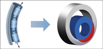
Long rotating times and severe doglegs can jeopardize casing integrity.Ali Y. Garkasi, Drilling Consultant; Yanghua Xiang and Gefei Liu, Pegasus Vertex Inc. Using mud motors or rotary steerable systems (RSS) to drill horizontal, extended reach (ER) and multilateral (ML) wells across the reservoir out of 7-in. production casing or liner requires relatively long rotating time in 9⅝-in. and 7-in. casing. It was observed that casing wear resulting from drilling and back-reaming in those wells could have a significant impact on the integrity of the 9⅝-in. intermediate casing string and the 7-in. production casing or liner. This casing wear is attributed to the increased side force caused by the drillstring tension that occurs while drilling and back-reaming to overcome high torque and drag in the open hole. In a dogleg section, the side force pushes the rotating tool joint against the casing wall, cutting a crescent-shaped groove in the casing wall that can jeopardize the casing integrity. The casing wear phenomenon was analyzed and evaluated for selected offshore and onshore ER and ML wells from a Middle Eastern drilling operation. Casing wear was observed in the 9⅝-in. casing and 7-in. liner strings while monitoring the wells while drilling. INTRODUCTION Oilfield developments are experiencing new challenges while drilling more complex ER (9,000 ft to over 30,000 ft) and ML wells (20,000–25,000 ft of reservoir exposure). These wells can be of either large-hole or slimhole designs with 7-in. production casing or liner typically set on top of the reservoir. While drilling the 8½-in. main bore out of an intermediate 9⅝-in. casing in ER and/or ML wells, depending on the length of the 8½-in. section and the geometry of the well trajectory, the 9⅝-in. casing is exposed to the risk of casing wear that might result from long rotating time of the drillstring inside the 9⅝-in. casing. The same casing wear risk may occur in 7-in. casing or liner while drilling the 6⅛-in. section in ER wells. In critical wells where casing wear was expected, magnets were placed across the mud flow before the shale shaker to collect the accumulated metal shavings. The amount of metal collected is an indication of the severity of casing wear. The shape of the metal shavings is a good indication of the type of casing wear mechanism. If the shavings are in powder form, then the wear is attributed to grinding; if shreds of metal are observed, then the wear mechanism is an adhesive wear. CASE HISTORY The casing wear model that was applied in this study assumes that the metal volume worn away in a wear groove section is proportional to the frictional energy transmitted to the casing by a rotating tool joint, Fig. 1.
The transmitted frictional energy (in ft-lb) is defined as:
where µ is the friction factor, SFtj is the side force on the tool joint per ft (in lb/ft) and SD is the sliding distance traveled by the tool joint against the casing wall (in inches). The volume of casing wall removed per ft (in in.3/ft) in a given amount of time is mathematically expressed as:
where WF is the casing wear factor, defined as the ratio of the friction factor to the specific energy; SFdp is the side force on the drill pipe per foot (in lb/ft); Dtj is the tool joint OD (in inches); N is the rotary speed (in rpm); and t is the rotating time (in hours). For a typical water-based mud, WF can vary as follows: WF above 20 can be considered very high and may cause severe casing damage. The ER wells in this study were all drilled to a TD of 19,600 ft or more, while the ML wells were drilled with 20,000 ft or more of reservoir exposure out of two or three lateral branches. The ER and ML wells were drilled using mud motors or RSS. The drillstring rotation inside the 9⅝-in. and 7-in. casing/liner is about 50 rpm using mud motors. Using RSS, the drillstring rotation is 150–170 rpm in the 9⅝-in. casing while drilling the 8½-in. hole section and is 130–140 rpm in the 7-in. casing or liner while drilling the 6⅛-in. hole section. The rotating time of the 61⁄8-in. drillstring inside the 9⅝-in. and 7-in. casing/liner in the ER or ML wells can be 500 hr or more, depending on the ER length or the number of branches of the ML well, respectively. Factors affecting casing wear include rotating times inside the casing; tool joint surface characteristics (i.e., steel or hard-banded); mud type, properties and solids content; tension and resultant side force during back-reaming; and dogleg severity. The contact between tool joint body and internal casing surface is greatly affected by the fluid between the surfaces. There are four well-known casing wear mechanisms: When TD of the ER or ML well is reached, a back-reaming trip is performed from the TD to the 7-in. casing/liner shoe to smooth the well by knocking down ledges and cleaning out the hole from the residual cuttings accumulated on the low side of the hole while drilling. In certain ER wells, increased torque-and-drag and overpull in the range of 30–50 kips and sometimes higher was observed due to micro-doglegs, tortuosity, other borehole irregularities and accumulation of cuttings at the low side of the hole. Depending on the overpull magnitude, the drillstring tension—and therefore side forces acting on the casing internal wall—can become very large, causing severe casing wear.
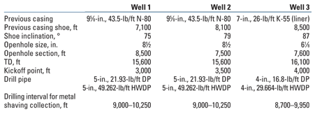
DISCUSSION AND EVALUATION Casing wear was studied in three ER wells, Table 1. Casing metal shavings were collected during drilling so that computer modeling could be compared with field measurement. A reasonable agreement was observed between the calculated casing wear volume and the volume of metal shavings over time for all three wells (Fig. 2), demonstrating that software modeling can be useful in predicting the magnitude and locations of casing wear.
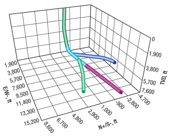
An ML well was selected to study the casing wear in 9⅝-in. casing while drilling the 8½-in. main bore; the casing wear in 7-in. liner; and the accumulated wear in 9⅝-in. casing while drilling the 6⅛-in. ER section and while drilling the two 6⅛-in. lateral branches out of two windows in the 7-in. liner, Fig. 3.
The casing design of the ML well was as follows: The 8½-in. main bore was drilled from 7,200 ft to 12,300 ft, and 7-in. liner was run and set at 12,300 ft. The casing wear model calculated the initial wear in 9⅝-in. casing while drilling this section. The BHA used new 5-in., 29.3-lb/ft drill pipe, 5-in., 21.9-lb/ft drill pipe and 5-in., 49.262-lb/ft heavyweight drill pipe. RSS was applied with an 8½-in. PDC bit. The extended 6⅛-in. main bore was drilled from 12,300 to 19,600 ft with a minimum build rate and reached an inclination of 88° at TD. The BHA used new 5-in., 29.3-lb/ft drill pipe, 4-in., 16.8-lb/ft drill pipe and 4-in., 29.6-lb/ft heavyweight drill pipe. RSS was applied with a 6⅛-in. PDC bit. The same BHA was used while drilling Lateral 1 and Lateral 2. The BHA was pulled out, and a one-trip whipstock was run and set at about 9,800 ft to drill Lateral 1. Additional casing wear in the 9⅝-in. casing and in the top part of the 7-in. liner (6,700–9,800 ft) was observed while drilling Lateral 1. The whipstock was pulled out. Another whipstock was run in and set at 8,800 ft, and Lateral 2 was drilled. Additional wear was observed in the 9⅝-in. casing and in the top section of the 7-in. liner (6,700–8,800 ft) while drilling Lateral 2. Both laterals were drilled with a build rate of 5–6°/100 ft, and a turn from 30°/100 ft to 50°/100 ft was required to reach the target point at the reservoir. In both laterals, a motor was used to initiate the curve after milling the window in the 7-in. liner, and then RSS was used to finish the lateral. Other drilling parameters are listed in Table 2.
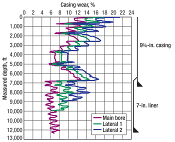
The predicted wear using the casing wear model at different drilling stages for 9⅝-in. casing and 7-in. liner is shown in Fig. 4. Note that wear starts at the top of the casing because string tension due to the dogleg is highest near surface.
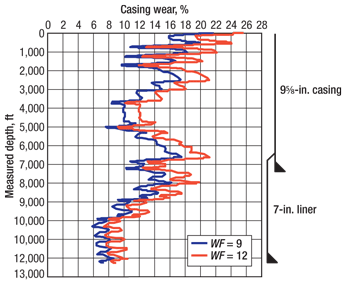
The initial wear in the 9⅝-in. casing while drilling the 8½-in. hole was around 12% at the upper part of hole. After more rotation while drilling Lateral 1, the wear had increased to 15%, and after drilling Lateral 2 it went up to over 18%. It is obvious that more rotation is always associated with more accumulated casing wear. In general, the wear of the upper part of the casing is always higher than that of the lower part due to the higher tension force of the rotating drillstring near surface. Figure 5 shows the impact of the wear factor on the casing wear in the 9⅝-in. casing and the 7-in. liner; by changing the wear factor from 9 to 12, the casing wear at 1,000-ft depth increases from 18% to over 22%. Possible causes of the wear factor increase include cuttings buildup, mud property change and a change of material in the tool joint surface.
CONCLUSIONS AND RECOMMENDATIONS ER and ML wells have a high casing wear risk due to their long rotating times. Operators may not realize the risk of casing wear until catastrophe occurs. Minimizing the back-reaming effect could help in reducing the drillstring overpull and tension. Software modeling of casing wear has been found useful in the planning stage and during job execution. Torque-and-drag software should be used to determine the magnitude of the drillstring tension force. Use of an RSS system will increase the rate of penetration and, thus, reduce the rotating time, which will lower casing wear. A smooth well trajectory and minimal dogleg severity will also reduce casing wear magnitude. Casing with a heavy wall should be used in well sections where heavy wear is anticipated. Variation of mud properties, addition of lubricants and the use of drill pipe protectors can also help reduce casing wear.
|
||||||||||||||||||||||||||||||||||||||||||||||||||||||||||
- Coiled tubing drilling’s role in the energy transition (March 2024)
- Using data to create new completion efficiencies (February 2024)
- Digital tool kit enhances real-time decision-making to improve drilling efficiency and performance (February 2024)
- E&P outside the U.S. maintains a disciplined pace (February 2024)
- U.S. operators reduce activity as crude prices plunge (February 2024)
- Drilling advances (January 2024)

