Studies conducted in Saudi Arabian wells illustrate issues that bear on expanding casing in high-angle and horizontal wellbores.
Patrick York, Tom Sanders, Jeffrey Teo and Raju Gandikota,
Weatherford International Ltd.; Shaohua Zhou, Saudi Aramco;
and Thomas Joulaud, Vallourec & Mannesmann Oil & Gas, France
Openhole expandable liners have been used in a variety of applications since their introduction roughly 11 years ago. One of the most challenging is their use as expandable production liners in the high-angle trajectories and long horizontal wellbores used in maximum-reservoir-contact (MRC) designs.
In these applications, openhole expandable liners are used to extend the casing string for greater exposure to the reservoir while minimizing the slimming of the well. MRC designs yield considerable advantages that are saving poorly performing wells and significantly increasing production and recoverable reserves, putting these older wells and fields on track for a recoverable reserves increase of 30% to 45%, with theoretical capability to increase reserves to as much as 75%.
However, these horizontal MRC wellbores also present mechanical and differential sticking conditions that pose unique challenges for the installation of expandable liners. The stresses these conditions impose on the expandable systems, inclusive of casing and its connections, can carry a substantial operational risk if stringent quality assurance measures are not taken.
Extensive studies of 14 installed expandable liners have provided new insights into expandable installation and performance in a variety of challenging horizontal wellbores. Initial results of these ongoing studies, conducted in an onshore Saudi Arabian oil field, yielded recommendations to improve the installation, zonal isolation and tubular performance of openhole production liners.
UNIQUE STICKING PROBLEMS
Differential sticking is a particular challenge in these applications because of how expandable pipe expands. In a typical installation, material balance physics determine that the expandable liner contracts in length as it expands in diameter. This shrinkage is typically 4% to 6%. Expanding a 1,000-ft liner by about 13% in diameter redistributes enough steel to reduce the pipe’s length by about 5%, or 50 ft.
When the casing is expanded from the bottom of the liner toward the top, the reduction in its length (or shrinkage) is easily compensated for by adding to the length of the unexpanded pipe. This excess liner is added within the overlap between the expanding casing and the casing that is being extended.
However, when the liner cannot move as its diameter is expanded, it cannot gain material from its length to maintain a material balance. Instead, the material volume must come from the liner’s wall and its connectors. This creates very demanding expansion requirements that call for engineering that applies a stringent qualification regime for the expandable system.
In the study applications, much of the focus was on connector qualification. While the collapse and burst pressure ratings of the casing and its connectors are degraded by the material balance exchange in differentially stuck expansions (and thickness of both may vary considerably from the uniform reduction that is theoretically predicted), this was not a significant factor in the study wells, since most were completed openhole or barefoot in carbonate reservoirs where the risk of hole collapse was not a factor. However, changes in these specifications must be taken into consideration in well planning.
In addition, mechanical manipulation to work the liner to final setting depth is limited with expandable liners. An inability to rotate places limits on compression and tension, restricting movement if the liner becomes stuck. As a result, stabilizing losses, under-reaming ledges, and working through dog-leg severity (DLS) intervals are more difficult actions when installing expandable liners.
Installation success in these demanding conditions is contingent on a fully qualified expandable liner system, in-depth planning, proper wellbore clean-out to prepare the well, and the ability to make immediate decisions at the rig-floor level of operations.
QUALIFYING CONNECTORS
Because flush-joint casing connectors have a lower performance limit than the pipe body, they are the most vulnerable component of the expansion process. Eliminating operational risks due to connection failure has been the objective of much effort by some expandable providers to understand, design, test and qualify expandable connectors.
This qualification process generally considers pre- and post-expansion properties. However, the highest risk factor of connection failure is associated with the expansion process itself. The three main mechanisms of connection failure during expansion are structural failure, due to damage or exceeding specifications; erosion and washouts, caused by a leak in the connection seal; and tensile failure related to stresses caused by mechanical or differential sticking.
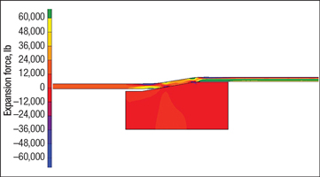
When expandable casing becomes differentially stuck while it is being run and expanded, axial stress in the pipe can exceed 56% of the yield stress. If connectors do not have at least 56% efficiency, they will begin to fail in tension, either in front of or behind the expansion surface. As a result, it is important to properly design, test and measure connection efficiency, Fig. 1.
 |
|
Fig. 1. Finite-element analysis of expansion in “fixed-fixed” conditions illustrates the cone expansion force and the reaction forces ahead of and behind the cone.
|
|
FIXED-FIXED EXPANSION
A fixed-fixed expansion is typically described as one in which a length of casing is differentially stuck in multiple places. However, it can be more accurately described as any situation in which a length of casing is not free to move.
This can occur if the casing is differentially stuck in one or more places along the length of casing being expanded. It can also occur when the wellbore surface area in contact with expandable casing creates enough frictional force to prevent the casing from shrinking during the expansion process. This can occur because the bottom of the liner is in contact with a wellbore over a continuous length, or at points where the wellbore direction is changing.
Expansion in fixed-fixed conditions not only puts the connector in extreme stress; it also changes the behavior and position of the connection’s metal-to-metal seal after expansion. If the seal is not designed specifically for the condition, the connector can easily lose its sealing capacity after expansion, resulting in connection erosion during and after expansion, leading to a connector washout and eventual catastrophic failure.
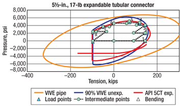
Currently, no special industry requirements exist to qualify expandable connectors for defect tolerance and reliability in fixed-fixed conditions. This type of testing should become a major part of the expandable connector qualification process. The systems referenced here have been extensively tested to define the connector operational envelope and have been confirmed in a fixed-fixed environment, Fig. 2.
 |
|
Fig. 2. Connector qualification is a key step. This graph shows the performance test envelope (expanded sample) for a 5½-in. expandable tubular connector used in the case history liners.
|
|
STICKING VARIATIONS
When the movement of any part of a length of casing is restrained during the expansion process, one or more of several situations can occur: the bottom of the liner will shrink off the bottom of the hole, the liner’s wall will thin and the liner will not shorten during the interval where the liner is unable to move, and/or, conversely, the liner will shorten only from the point that it is able to move to the top of the liner.
The amount of liner shortening during expansion can be calculated by knowing the amount of expansion that would take place if the liner was free to move. Several components of the expansion process must be monitored and analyzed. Two of these are the expansion pressure and the weight indicator reading (WIR). These parameters contribute to the total expansion force required to expand the casing.
It is also important to understand that more force is required to expand stuck casing than if the casing is free to shorten during the expansion process. In addition, the force to expand differentially stuck pipe can be greater than that required to expand immobile pipe. This is due to larger local forces that are exerted on the pipe as the result of differential pressure pressing the casing against the wellbore.
This action can also prevent the casing from shortening during the expansion process. Whether this happens in one place or several places along the length of the liner, it changes the normal expansion process and significantly increases forces on the liner.
When the liner contact is on the low side of the horizontal wellbore, frictional drag may also reduce liner shrinkage. As the liner is expanded, the angle of contact increases, which increases frictional drag.
This drag can be sufficient to cause differential sticking. Considerable field experience running long expandable liners in horizontal reservoir sections confirms that if running speed is slowed or stopped in the porous reservoir section, there is always a high tendency for the expandable liner to become differentially stuck.
INSTALLATION SCENARIOS
These various responses to expanding a stuck liner result in several installation scenarios. For instance, the liner may constantly move either up or down the hole. It may experience scoping, in which the liner is forced off the cone and down the hole as it is being expanded. The liner can be dragged upward and stick at a second point or at multiple points above the bottom sticking point. It can also be pushed down to a sticking point.
If the frictional force on the liner is more than the pressure-derived force created with the expansion pressure, the expandable liner will be unable to shorten during expansion. The expandable liner may also remain on depth, become stuck at TD, or remain at target depth due to manipulation of the pump pressure and WIR.
MRC WELL DESIGN
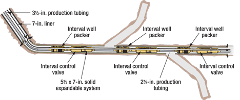
In the Saudi Arabian field that was studied, solid expandable systems have been used primarily to extend the 7-in. shoe of the existing casing string. Low-angle whipstocks are then set inside the expanded casing, and multiple laterals are drilled, Fig. 3.
 |
|
Fig. 3. A completion schematic from Well B shows a simplified smart completion inside a solid expandable liner.
|
|
The expanded production liner provides a conduit for implementing a smart completion as well as cemented zonal isolation while retaining sufficient reservoir hole size (11.3% reduction with expandable liner versus 58% size reduction with a conventional system). The wells are completed with smart equipment if the flow control from each lateral is critical after re-entry workover, or as simple openhole producers if flow control can be deferred to the future.
To accommodate the liner installations, the wellbores are enlarged by under-reaming from 6⅛ in. to 7¼ in. In another typical application, the sidetrack wellbores are created through a window exit with a medium-to-long build rate with actual DLS up to 15°/100 ft.
Excellent results have been achieved with MRC well designs. Production has improved as much as 5,000 bbl/day in a few wells. One formerly nonproductive well is now producing 10,000 bbl/day.
This positive production response has established the value of expandable technology for the field. The studies were conducted to further understand and refine the planning and installation process.
WELL STUDIES
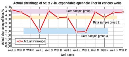
The studies were conducted on 14 expandable liners with various wellbore inclinations and liner mobility, drilled primarily in carbonate formations using similar mud systems. The wells were categorized in three groups (according to observed shrinkage), Fig. 4.
 |
|
Fig. 4. The study wells were grouped according to the degree of observed shortening of the 5½ x 7-in. expandable openhole liners in various well environments.
|
|
Theoretically, liners with total mobility should have shortened 4.7% during the expansion process. The average shortening of the subject liners was about 3.6%.
The first group consisted of wells where shrinkage closely matched the calculated 4.7%. Interestingly, three of these six installations were through windows with relatively high DLS (12°/100 ft to 15°/100 ft). Inclination of one well was only 40°, while the other well inclinations were about 90°.
The second group consisted of four wells (D, H, J and N). Liner shrinkage in this group was less than average at 3.71%. Some mobility was present during the expansion of these liners. In one well (Well N), the inclination was only 45°, while inclination in the other wells was about 90°.
Unique to this group of wells was Well H, where centralizers were used on the expandable liner. The end results were lower friction and better standoff, which led to a better cement job as evidenced by cement evaluation logs. The centralizers did not interfere with the liner expansion.
GROUP 3 ANALYSIS
Much of the analysis centers on the third group of wells (E, K and L), which exhibited some of the largest differences between the calculated and actual liner shrinkage. Table 1 provides insight into some of the liners’ “before” and “after” liner lengths, what shrinkage was expected and what was observed.
| TABLE 1. Data table highlighting pre- and post-liner expansion lengths and well positions for Wells K, E and L |
 |
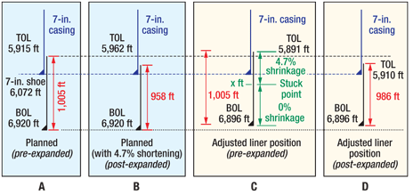
For Well K, the analysis involved a fixed-fixed expansion. It appeared from the initial analysis that, before expansion began, the expandable liner was pulled up the hole to a certain depth where it ceased to move. A study of Fig. 5 presents the following case:
Although the liner in Well K was run to a depth of 6,920 ft at TD, during drillout it was discovered that the BOL was located at 6,896 ft, or about 24 ft higher from its original position. The liner was expanded about 14% in diameter (ID to ID) and the calculated shrinkage of the liner was 4.7%. As seen in Table 1, the actual shrinkage was 1.89%. When the liner was expanded, either the frictional forces between the liner and the wellbore became large enough to stop the liner from shortening, or the bottom of liner (BOL) became differentially stuck in two or more places along its length. The following calculation provides a means to determine the length of liner that was not able to shorten during expansion.
 |
|
Fig. 5. Planned versus observed positioning and shortening in Well K.
|
|
Calculating top stuck point depth. In order to make this calculation, a number of assumptions are considered:
1. Fixed-fixed expansion occurs (two stuck points).
2. The expandable liner shrinks at a factor of 4.7%.
3. The expandable liner has been dragged up the hole to 6,896 ft and stuck at this depth before expansion begins.
4. The expandable liner has a top stuck point at an unknown depth (x ft).
5. There is no shrinkage in the section of liner between the two stuck points.
The formula for calculating the upper location of the stuck point of liner (x) is:
(BOL1 – x) + EF(x – TOL1) = LLPE
where:
• BOL1 is the BOL before expansion.
• TOL1 is the TOL before expansion.
• EF is the expansion factor, which is 100% minus the calculated percentage of expansion. The expansion factor is a factor that converts the original length to the shortened liner length.
• LLPE is the shortened liner length after expansion.
Substituting Well K data into the formula, BOL after repositioning of the liner (assuming that it was pulled up the hole 24 ft) is 6,896 ft. TOL after expansion is 5,891 ft. The expansion factor, using a calculated shrinkage value (given) of 4.7%, is 0.953. The final length of liner after expansion is 986 ft.
Plugging this data into the equation yields:
(6,896 – x) + 0.953(x – 5,891) = 986
which produces an x value of 6,298 ft. Therefore, the bottom of the expandable liner in Well K was stuck about 24 ft off its original TD at 6,896 ft and the top stuck point was 6,298 ft, which is 598 ft above the bottom.
DIAGNOSING DOWNHOLE EVENTS
The same calculation method is also used to determine the length of immobile or stuck liners. A longer-than-planned post-expansion length means there must be a length of pipe that has expanded without shortening. Given the actual top and bottom liner measurements, the length of immobile liner can be calculated. It is simply the difference between the actual BOL and the point where the liner is differentially stuck.
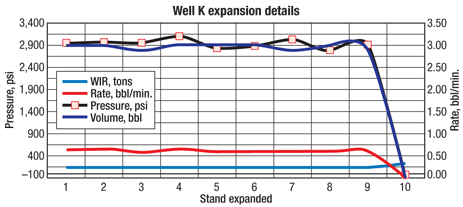
In Well K, the WIR was 136 kips at the initial expansion and dropped to about 130 kips for the next four stands. At the fifth stand, there was a gain of 10 kips at a depth of 6,299 ft. This depth is very close to the calculated differential sticking point of 6,298 ft. From the fifth stand onward, the WIR stayed at about 140 kips until the cone exited the top of the liner.
This is contrary to the assumption that an expandable liner does not shrink below the point where it is differentially stuck. The WIR suggests shrinkage below the differentially stuck point and little or no shrinkage above that point.
Another means of determining the location of the immobile liner is to establish the stuck points from WIR and pump pressure during expansion. If there is more pulling force, less pump pressure will be needed for the expansion, and vice versa.
Stands 6 through 9 showed the highest WIR and a low interval pump pressure of 2,800 psi. With the same pulling force and pump rate, the pump pressure during expansion should be consistent unless a restriction exists, Fig. 6.
 |
|
Fig. 6. Well K expansion details show variations in WIR and interval pump pressure. With the same pulling force and pump rate, the pump pressure during expansion should be consistent unless a restriction exists.
|
|
If the pump pressure exceeds 2,800 psi, it indicates a possible restriction in the annulus outside of the expanding liner. Depending on the resistance in the formation on the OD of the liner, the pump pressure would increase accordingly.
There is more resistance on the outside of the expandable liner while the cone is passing through it. During this fixed-fixed expansion, the liner’s wall gets thinner. There may be a certain degree of liner spring-back due to the formation rebounding after the expansion.
WELL E ANALYSIS
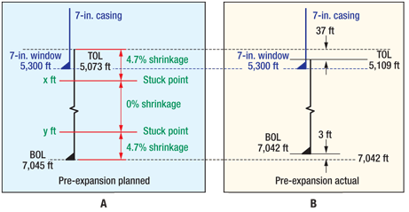
In Well E, the liner reached its planned TD of 7,045 ft. However, after drillout, the liner TD was 3 ft higher at 7,042 ft. Either the liner was pulled uphole before expansion began or it shrank from the bottom because the liner was stuck somewhere above TD, Fig. 7.
 |
|
Fig. 7. Planned versus observed positioning and shortening of the solid expandable liner in Well E.
|
|
Calculations showed where the liner was stuck near its bottom and subsequently indicated the top stuck point. For this installation, the WIR varied between 140 and 145 kips from the bottom to a depth of 5,913 ft, where it decreased to 135 kips. This depth, consistent with the theoretical differential sticking point, was again very close to the calculated stuck point at 5,900 ft and showed that a larger pull was required for that section.
The data were separated into two groups—below and above the differential sticking point. The WIRs were arranged in ascending order together with their relevant pump pressures and stand numbers. An increase in WIR should result in a decrease in pump pressure since the pump rate is constant, Table 2.
| TABLE 2. Expansion details from Well E indicating the section that may be differentially stuck |
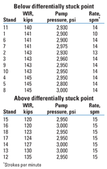 |
An increasing trend in which a higher WIR has a higher corresponding pump pressure illustrates that the liner is differentially stuck at this interval. The pump pressure remained constant at about 2,950 to 3,000 psi for expansion above the differential sticking point with increasing WIR. Although the pump pressure remained the same, the increase in WIR may be due to the increase in resistance on the outside of the expandable pipe, indicating that the section of the liner was differentially stuck. However, there is still a possibility that the entire liner was differentially stuck.
WELL L ANALYSIS
Well L presents a unique case. Pressure was lost during expansion at a depth of 8,318 ft, and the remaining liner was expanded by overpull. This indicates that the liner was stuck at some point(s), or it would have been dragged all the way to the top without expanding.
The stuck points could be above or below the theoretical sticking point or a combination of both. Before the pressure was lost, the WIR was constant at 198 kips for three stands before decreasing to 190 kips with constant pump pressure for the next nine stands. This implies that the liner was differentially stuck at the first three stands.
An examination of the WIR and pump pressure after the pump pressure was lost shows that the WIR increased to about 270 kips but decreased for the last two stands. When the cone reached an elastomer joint, the WIR was only 240 kips. This suggests that more force is required to expand the pipe body without the elastomers. This violates material balance, and, therefore, there must be resistance at the backside. It can be concluded that stuck points existed above and below the theoretical differentially stuck point, making it a redundant point of interest.
THE PROCESS FOR SUCCESS
Expanding casing in high-angle and horizontal wellbores can carry a large operational risk component if the system has not been extensively tested to handle extreme stresses on the expansion system and expandable casing. Many issues bear on these considerations, including fixed-fixed conditions, risk/cost evaluation, hazard operation evaluation and expansion parameters.
The Saudi Arabian well studies illustrate how selecting the correct equipment, retaining professionals to plan the installation with the direct involvement of the customer, and securing key personnel at the rigsite provide the right combination of conditions for successful installation of expandable liners. 
ACKNOWLEDGMENT
This article was prepared in part from SPE 124965 presented at the SPE Annual Technical Conference and Exhibition, Oct. 4–7, 2009.
Basics of an expandable openhole liner installation
Conventional casing-running equipment and pressure pumping practices are used in the running and expanding of the expandable openhole liner. The process is no more complex than installing a conventional drilling liner using an inner cement process.
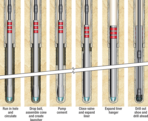
The running sequence for the openhole expandable liner system is simple and straightforward, as illustrated in Fig. 1.
 |
|
Fig. 1. Running sequence of an openhole liner system.
|
|
Detail of running procedure:
1. Run system in the under-reamed hole. The wellhole is typically under-reamed to accommodate the size of the annulus that is required between the expanded liner and the wellbore to allow for sufficient cement thickness to create good zonal isolation between the exposed formations that the liner will cover.
2. Form cone by assembling. Once the expandable liner is run to TD, a ball is dropped and the system’s expansion cone is assembled.
3. Cement expandable liner. Once the cone assembly is complete, the setting ball falls to a secondary position, allowing full circulation ability to be regained.
The retarded cement is pumped and placed around the unexpanded liner. The cement is then retarded sufficiently that it will allow the liner to be fully expanded before it begins to set.
A conventional dart catcher (not shown) is run above the expandable system’s running tools. A lead dart is dropped in front of the cement job and another after the cement is pumped.
4. Close system’s valve and expand liner. Once the cement pumping is complete, a valve in the expandable liner’s bottomhole assembly is closed by rotating the drillstring. This facilitates sealing off or hydraulically isolating the inside of the expandable liner to the wellbore.
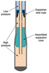
This isolation allows pump pressure to be increased. The drilling fluid is pumped into the expandable liner and is trapped between the closed valve within the system’s BHA and a set of expansion seal cups above the expansion cone, Fig. 2.
 |
|
Fig. 2. Drilling fluid is pumped into the expandable liner. The fluid becomes trapped between the closed valve within the system’s bottomhole assembly and a set of expansion seal cups above the expansion cone.
|
|
This creates a pressure differential across the expansion seal cups.
This differential pressure (typically between 2,000 psi and 3,000 psi) creates enough mechanical force to expand the casing. The casing is forced to bottom as the liner is expanded during the expansion process.
Once a stand of casing is expanded, the pump pressure is lowered to zero pressure, the slips are set on the drillstring and the stand is unscrewed and set back in the derrick.
The top drive is made up to the drillstring once again, and the expansion process is repeated until the entire liner is expanded.
5. Expand liner hanger. The liner hanger is made up of a set of elastomeric seals (three to five bands of elastomer about 6 in. in width and about 1⁄8 in. in thickness) molded onto an expandable machined steel body.
The expansion process continues as in step 4, expanding the liner hanger body, compressing the elastomeric seals between the expanding casing and the inside diameter of the shoe of the previous string of casing.
Expanding the liner hanger creates both a mechanical anchor and a hydraulic seal at the top of the liner.
6. Drill out shoe. Once the liner and its liner hanger are fully expanded, the drillstring with the expansion tool is pulled out of the hole. A drillout bit is run into the hole, and the expandable liner’s shoe is drilled out.
|
THE AUTHORS
|
| |
Patrick York has 36 years of industry experience and is the Director of Commercialization for the solid expandables business unit for Weatherford. He received his BS degree in electrical engineering at Northwestern State University and pursued his MBA degree there in economics and management.
|
|
| |
Tom Sanders is Operations Manager for the Solids Expandables product/service line for Weatherford International Ltd. Before joining Weatherford, he was the Middle East/Caspian Regional Operations Manager for Enventure Global Technology after his tenure with Halliburton.
|
|
| |
Jeffrey Teo is a Support Engineer for the solid expandables product/service line for Weatherford. He is based in Singapore.
|
|
| |
Raju Gandikota is a Senior Research Engineer for the Weatherford solid expandables product/service line. He received his BS degree in mechanical engineering from Madras University, India, and an MS degree in industrial and manufacturing engineering from Wichita State University.
|
|
| |
Shaohua Zhou is a Petroleum Engineering Consultant for the Drilling Technology Team, Exploration and Petroleum Engineering Center–Advanced Research Center of Saudi Aramco. He received his BS and MS degrees in applied geophysics from Chengdu University of Technology in China and his PhD degree in geosciences from the University of Adelaide in Australia.
|
|
| |
Thomas Joulaud is currently acting as Technical Support with Vallourec & Mannesmann. He headed development of expandable products until mid-2009.
|
|
| |
|
|


