Using computational fluid dynamics simulations, a new internals design was demonstrated to greatly improve volumetric utilization, allowing the operator to double the process flowrate.
Daniel W. Phelps, Rafiqul I. Khan and Joseph M. Lee, Cameron;
Paul Andrews and Dan Marlowe, Chevron North America
Internals designed for an existing moderate-sized skim tank (10,000-bbl nominal volume) were studied using computational fluid dynamics (CFD) simulations. The proposed internals included an inlet distribution system, perforated baffles for flow control, an oil skim mechanism and a controlled water flow outlet. The inlet was designed to uniformly distribute fluid across the inlet perforated baffle, to have minimal pressure drop, and to allow sand cleanout. The inlet perforated baffle was designed with sufficient pressure drop to provide flow control and uniform flow across the skim tank. The exit perforated baffle was similarly designed, with sufficient pressure drop to control the flow to the water outlet. A skim trough was designed across the exit perforated plate baffle for skimming the oil and excess water to an exit oil bucket with sufficient volume for flow control. The water outlet was designed with controlled flow through perforated plates prior to exit through staggered outlet nozzles.
CFD simulations were performed on the skim tank with the recommended internals to evaluate the separation efficiency. CFD simulation was also performed without the two large perforated baffles. Results indicated a satisfactory performance of the tank with the proposed internals, but showed poor performance without the two large perforated baffles. Using the particle residence time analysis at a produced water flowrate of 100,000 bpd, it was concluded that the volumetric utilization of the skim tank was 70% with baffles and only 30% without baffles. Particle tracking results also indicated that a droplet size as small as 150 microns could be removed from the tank with baffles, while the largest droplet size that could be removed without baffles was 250 microns.
Oil-in-water measurement results with this improved design indicate that the oil concentration decreased by about 15% with a 100% increase in the water volume flowing through the vessel.
PROJECT OBJECTIVES
The project was to design and evaluate, by CFD, improved internals for an oil/water skim tank. Cameron has experience designing this type of equipment and has previously conducted CFD studies on skim tanks to evaluate the internals’ performance.
An inlet distribution system and internal perforated baffles were designed for the skim tank, and the design was validated using CFD simulations in Fluent 6.3 software. The objectives of this CFD study were to:
• Model the geometry of the skim tank with the designed internals
• Mesh the flow domain, define phase boundaries and set up the CFD files
• Model the transient simulation under the specified operating conditions
• Evaluate the overall volumetric utilization (a measure of separation efficiency)
• Model the oil particle flow and oil/water separation through the vessel
• Understand the fluid flow patterns developed inside the tank.
The main project objectives were to design the improved tank internals and to evaluate their performance.
SKIM TANK DESIGN
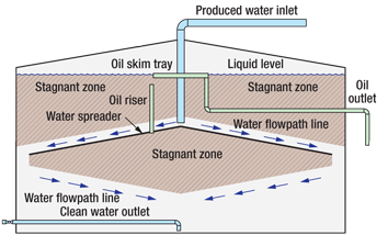
The skim tank was 48 ft in diameter and 30 ft tall, with a theoretical water retention time of 2 hr at maximum flowrate. Figure 1 shows typical internals for older skim tanks similar (but not identical) to the Chevron tank modified.
 |
|
Fig. 1. Typical skim tank and internals.
|
|
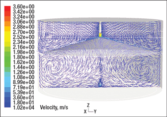
Inspection of typical skim tank internals shows that the upper zones and the area below the distribution cone will not be effectively used, as the water will seek the most direct path between the inlet and outlet nozzles. Thus, the water will channel down the top of the distribution cone and from the edges of the cone directly to the single-point water outlet nozzle, leaving large areas of the skim tank with no controlled water flow to them. A CFD analysis of the internal tank geometry showed this flow pattern and indicated large recirculation zones in the upper areas of the tank and in the area below the distribution cone, Fig. 2. These flow patterns would drastically reduce the effective utilization of the tank volume.
 |
|
Fig. 2. A CFD analysis of flow patterns in the skim tank indicated large recirculation zones that would drastically reduce the effective utilization of the tank volume.
|
|
With a flowrate of about 35,000 bpd, the existing skim tank reduced oil-in-water to about 100–120 ppm at the outlet from between 150 and 600 ppm at the inlet. For a higher throughput of 100,000 bpd, the outlet oil-in-water value would rise to an unacceptable level to feed the downstream processes. Maintaining acceptable oil-in-water output at the increased throughput would require that the full tank volume be effectively utilized, which meant the water flow must be controlled and managed.
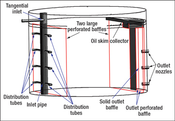
For the improved tank internals, a liquid level of 26 ft was chosen, that being the maximum water level that allowed for the proper levels of piping connections and sufficient downstream operating head. Based on the flowrate and fluid properties (Table 1), tank internals were designed for more efficient oil/water separation, Fig. 3.
| TABLE 1. Flowrates and fluid properties of the produced water |
 |
 |
|
Fig. 3. Proposed improvements to the skim tank.
|
|
A modified gas-liquid cylindrical cyclone (GLCC)-type inlet system was designed to promote gas/liquid separation and evenly distribute the liquid stream throughout the inlet portion of the tank. The majority of the gas phase separates quickly and immediately exits from the inlet device to a gas nozzle directly out of the tank, removing almost any chance of gas pressure buildup and overpressure inside the skim tank from upset conditions. In this application, the incoming fluid contained a very small amount of gas, which was vented directly into the tank with less than about 2 in. of water pressure to provide a gas blanket for corrosion prevention.
From the GLCC-type inlet pipe, the fluid exits to both sides of the tank through eight parallel distribution tubes. The bottom of the inlet pipe has a tapered section to promote the removal of any solids. Solids collected can be flushed out through the drain. The open end of each distribution tube is directed toward the wall of the skim tank and employs the tank wall as a momentum breaker.
Two large perforated plate baffles are placed downstream of the inlet to achieve better flow uniformity and minimize recirculation. One baffle is placed near the inlet distributor to control and distribute the flow across the tank, and the other is placed near the water exit to control the flow to the water outlet nozzles and the oil skimming collector. Additional perforated plate baffles surrounding the water outlet nozzles prevent possible flow short-circuiting. A solid baffle was placed parallel to the large perforated plates, and two perforated baffles were placed on either side of the solid baffle and perpendicular to it. It is important to note that the normal forces acting on the baffle walls are quite large and that the support design must be carefully engineered both to provide adequate support of the walls and to avoid tank wall structural deformation.
Also in the new design, oil is drawn off into an oil trough over a weir. This trough is placed in front of the exit perforated plate to promote removal of oil before it can reach the exit perforated plate baffle and be carried to the water exit. The oil trough slopes to the center of the tank and drains at the center into an oil bucket, which can have a level control. Water from the skim tank exits through perforated plate baffles to three outlet nozzles at staggered positions, designed for uniform water exit.
CFD RESULTS AND DISCUSSION
The three-dimensional model of the skim tank geometry was constructed based on the data (tank dimensions, flowrates, fluid properties, etc.) provided. The tank was simplified based on some reasonable assumptions to minimize computational efforts. For the CFD calculations, only the liquid section of the tank was considered, since the fluid entering into the tank contained very little entrained gas. In addition, the domain inside the inlet tube was ignored to minimize the computational time.
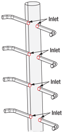
This simplified tank domain was subdivided into small volumes (meshed) for detailed CFD calculations. The perforated plates were modeled as porous jump boundaries to minimize meshing complexity. The oil trough was simplified by ignoring the V-notch slot details and their inclinations. Identical mass flow through all eight distribution tubes (confirmed by a study at Cameron) was assumed, so flow through the large inlet tube was not modeled. Inlet boundaries were considered to be at the beginning of the distribution tubes as shown in Fig. 4.
 |
|
Fig. 4. Geometric details of the modeled distribution pipes, with inlet boundaries at the red circles.
|
|
For the residence time calculation, a single phase calculation was performed until a fully converged flow field was achieved. Water particles of 1 micron in size (sufficiently small particles that closely followed the flow field) were then injected from the eight inlet boundaries, and the actual residence time (ART) required to exit through the outlet boundaries was determined.
Theoretical residence time (TRT) was calculated by simply dividing the total liquid volume in the tank by the liquid flowrates entering into the vessel. This is the ideal or maximum residence time that will allow the best possible separation. The ART/TRT ratio defines the volumetric utilization of the liquid phase within the tank. Separation efficiency is expected to improve with increased residence time and volumetric utilization. CFD results were also used to visualize the flow patterns. Calculations were performed with and without the presence of the perforated baffles for the skim tank with the same inlet distribution system.
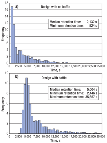
Volumetric utilization analysis. The time histogram plots of the water particles graphically summarize the distribution of the number frequencies of particles requiring various time ranges to exit though the outlet boundaries. Figure 5 shows the time histogram plots of particle residence time calculated for the two designs: with and without baffles. Both designs have a TRT of 7,185 s, calculated based on the tank’s liquid volume and inlet flowrate. The mean ART of the design without perforated plates is 2,132 s, about 30% of the TRT, indicating a poor utilization of the liquid volume. This clearly indicates that flow is short-circuiting inside the skim tank. For the case with perforated baffles, the ART of the produced water improved to 5,004 s, almost 70% of the theoretical value, indicating a significant improvement of the volumetric utilization.
 |
|
Fig. 5. Actual residence time histogram a) without perforated baffles and b) with perforated baffles.
|
|
Furthermore, the residence time of the first particles exiting through the water outlet boundaries was 2,446 s for the tank with baffles, almost five times as long as for the tank without baffles (524 s). These results suggest a large improvement of liquid volume utilization due to the placement of the perforated plates.
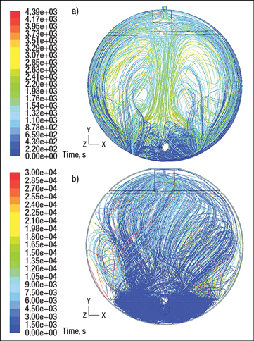
Figure 6 shows flow path lines colored by residence time for cases without and with the perforated baffles. The two large swirling patterns in the tank without baffles (Fig. 6a) are characteristic of severe flow recirculation and short-circuiting. When baffles are included (Fig. 6b), the path lines show significantly reduced recirculation patterns, indicating better utilization of the tank volume.
 |
|
Fig. 6. Colored path lines indicate residence time of water particles for the tank designs a) without perforated baffles and b) with perforated baffles.
|
|
Carry-under of oil droplets in water phase. It is often desirable to know what size oil droplets are easily skimmed off for good oil/water separation. In order to evaluate the separation performance of the skim tank with designed internals, the oil particles of various sizes were injected from the inlet boundaries, and the time history of the particles exiting through the outlet boundaries was calculated. It should be noted that the CFD modeling is unable to simulate the coalescence of oil droplets over time. Therefore, the separation performance illustrated here is the worst case.
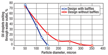
Side views of the tank with particle tracking for 50-micron, 100-micron, 125-micron and 150-micron oil droplets are shown in Fig. 7. Examination of these figures shows that substantial numbers of the 50-micron and 100-micron oil droplets exit though the water outlet boundaries. However, very few 125-micron particles escape through the water outlet, and almost negligible numbers of 150-micron droplets leave through the water outlet boundaries. In summary, with the implementation of designed internals, any oil droplets larger than 150-micron are likely to be skimmed off inside the skim tank at a produced water flowrate of 100,000 bpd. However, for the case without any baffles, results show that any droplets would need to be about 250 microns or larger to be skimmed off. Thus, the skim tank with the recommended baffles can skim off oil droplets that are much smaller than the tank without the recommended baffles.
 |
|
Fig. 7. Particle tracking of a) 50-micron, b) 100-micron, c) 125-micron and d) 150-micron oil droplets in the tank with baffles
|
|
Figure 8 shows the percentage of oil droplets of various sizes exiting through the water outlet boundaries. For the case with baffles, results show a more rapid decline of the percentage of oil particles exiting through the water outlets as a function of oil droplet sizes. However, the results for the case without baffles show a broader distribution, indicating poorer separation efficiency.
 |
|
Fig. 8. The percentage of oil droplets exiting through the water outlet boundaries is plotted as a function of oil droplet size for both tank designs.
|
|
VESSEL PERFORMANCE
After installation of the new internals, the water flowrate was doubled to 70,000 bpd (resulting in a 50% reduction in theoretical retention time). Inlet oil concentrations range from 150 ppm to 600 ppm depending on upstream operations and seasonality. In winter, the outlet concentration with the lower flowrate and old internals design had ranged 100–200 ppm. With the new baffle design and higher flowrate, the outlet concentration ranges 80–150 ppm. The summer outlet concentration has remained in the 40–80-ppm range, but with the higher water flowrate. The lower oil concentrations have allowed the induced gas flotation vessel following the skim tank to operate better in an attempt to maintain oil-in-water concentrations below 30 ppm with the increased flowrate. These results were obtained with intermittent skimming of the skim tank. Improved results would be obtained with continuous skimming, but a larger volume of skim oil/water would need to be treated.
BAFFLE WALL INSTALLATION
Installation of the baffle system can be done in one of two ways. To retrofit an existing tank, all materials must be dimensioned to fit through a typical tank manway (36 in.). The presence of other appurtenances (heating systems, sparging pipe, cathodic protection, etc.) inside the tank needs to be considered. The scaffolding and lifting systems used can be labor and material intensive, adding significantly to the cost of installation. The baffle systems are then fabricated off the scaffold inside the tank. First the structural support members in the steel framework are assembled, next the mounting lattice, and then the high-density polyethylene perforated sheets are put in place.
If, on the other hand, the baffle systems are to be installed in a new tank, installation is much easier. An entire baffle wall can be laid out and constructed adjacent to the new tank construction site and, once the shell of the tank is erected (but before the roof structure is in place), the baffle walls can be lifted and lowered into place with an onsite crane.
As stated above, the differential pressure across the non-void area of the baffle walls imposes a significant force normal to the wall. The bracing design and materials selection must be engineered to account for this force. It should also be noted that all attachment details for the baffle and weir system must comply with API 650 (current version) material, fabrication, erection and testing requirements. Other considerations involve corrosion protection for the new structure. Typically, produced water is fairly anoxic and the baffle walls remain submerged, reducing the expected rate of corrosion. However, the aqueous chemistry is not always the same, and it is certainly worth considering protective coatings and/or passive cathodic protection (anodes) on the steel portions of the structure.
CONCLUSIONS
Improvements can be made to older oil/water skim tanks that will improve the flow patterns and volumetric utilization, resulting in reduced oil-in-water concentrations or higher flowrate capacities. Results from CFD modeling demonstrate that improved internals designs can create flow patterns that more effectively utilize the skim tank volume in oil/water separation. Measured results confirm the modeling. The volumetric utilization of the skim tank in this study was improved to about 70%. Tanks with a larger diameter/height ratio would realize a greater improvement. Generally, skim tanks are designed with a diameter/height ratio of 2.0 or greater. 
|
THE AUTHORS
|
|
Daniel W. Phelps is a Senior Process Consultant at Cameron. He has a PhD degree in chemistry and several years’ experience providing technical evaluations and troubleshooting for oil and gas production and processing. He has designed onshore and offshore oil, gas and water processing equipment and has performed debottlenecking studies for onshore and offshore oil and gas processing.
|
|
|
Rafiqul I. Khan is a Senior Process Consultant at Cameron and has extensive industrial experience using CFD modeling. He has worked in the chemical and petrochemical industries on projects involving multiphase flows, erosion, porous media, heat transfer, turbulent mixing, cavitation, rotating machineries and valve design. He has a PhD degree in chemical engineering from Queen’s University in Kingston, Ontario, Canada.
|
|
|
Joseph M. Lee is Director of Process Solutions at Cameron. He has over 30 years’ experience in the oil and gas industry with firms including Natco, Amoco, BP and Halliburton. He holds BS, MS and PhD degrees in chemical engineering. For the last four years, Dr. Lee has served on the Society of Petroleum Engineers’ workshop and forum committees to facilitate technology transfer to the oil and gas industry. He has published more than 30 technical papers.
|
|
|
Paul Andrews performs facility engineering and project management functions in support of Chevron’s Cook Inlet, Alaska, onshore and offshore production facilities. He has an MEng degree in civil engineering from Clarkson University inw Potsdam, New York, and about five years of upstream oil and gas production experience.
|
|
|
Dan Marlowe manages chemical and corrosion programs in support of Chevron’s Cook Inlet onshore and offshore production facilities. His responsibilities include meeting discharge water quality requirements in accordance with NPDES regulations. He has a BEng degree in mechanical engineering from LeTourneau University in Longview, Texas, and about 15 years of upstream oil and gas production experience.
|
|


