Proper wear management helped complete a multi-well program and saved money on logistics, while using a single drillstring.
Richard F. Zoanni, S. DeWayne Everage and Thomas M. Wadsworth, T H Hill Associates, Inc.; and Juan P. Cassanelli, Pluspetrol Perú
Industry advances continue to enable operators to pursue more challenging drilling targets with complex wellbore trajectories in costly deepwater and/or remote operating areas. Demand for a practical, field-proven drill pipe fatigue management system has grown as drillstring fatigue failures contribute to non-productive time and cost. The response has been the development of an engineered approach that combines pipe section positioning and inspection scheduling, based on estimated fatigue damage rather than rotating hours or footage drilled. Successful real-time field implementation with ongoing drilling programs demonstrates that the cumulative fatigue damage technique is a valuable tool for risk mitigation and cost reduction.
The technique and its implementation have been introduced in previous literature.1–4 This method of monitoring fatigue damage due to rotary operations allows the pipe to be evaluated under real-time operating conditions along a specific section or the entire drill pipe length. Monitoring begins at spud and is performed on each drill pipe joint as it traverses along the well path to TD. This not only allows a quantitative measure of the relative fatigue damage, accumulated joint by joint for the drill pipe, but also provides the opportunity to manage logistics, forecast pipe inspections and position pipe sections to minimize cumulative drillstring fatigue damage.
This article provides a brief synopsis of the method followed for the final three wells of the Pagoreni six-well drilling program for Pluspetrol on Block 56 in Peru’s Southern Ucayali Basin. The operator originally anticipated that pipe inspection might be required before each well to mitigate costly drill pipe failures. However, the cost and logistical challenges of mid-program pipe inspection in remote operations could not be ignored.
The fracture mechanics-based method of modeling drillstring fatigue accumulation has been introduced and implemented in the field with encouraging results.4 Due to increased awareness and a growing need for accurate and reliable information about drill pipe condition and service life, the demand for using this approach has grown significantly in the four years since it was first introduced.3 Operators worldwide are beginning to dedicate significant resources to drill pipe management and string failure prevention. While using the cumulative fatigue method to support high-risk drilling programs, promising correlations have been made between inspection results following operations and real-time modeled fatigue projections.
Drilling programs that have experienced significant and repeated string failures in the past have since been drilled successfully without incident.2,4 This has been achieved through dedicated teams of operator and service personnel responsible for monitoring and tracking the pipe at the rig site, while implementing the cumulative fatigue model, often remotely.
CUMULATIVE FATIGUE
Cumulative fatigue analysis can be divided into three categories: hind casting, planning and real-time analysis.1 This article focuses on the latter two. In the planning stage of a project, a simulation analysis of planned drilling operations for each hole section from spud to TD is performed. The model estimates the relative level of drillstring fatigue accumulation during all rotary operations as the drill pipe is deployed from spud to TD. Based on these results, recommendations are made for pipe positioning and deployment schedule, inspection frequency and further design optimization. The pre-drill analyses suggest whether real-time fatigue monitoring is warranted.
During real-time monitoring, cumulative fatigue for each joint is estimated from rig-based digital recording systems. Comparisons between modeled real-time fatigue accumulation and pre-drill analysis results forecast any required drill pipe section repositioning and/or inspection, based on whether a pre-determined damage point cutoff has been reached.4 Monitoring fatigue damage in this manner allows the drilling team to minimize downtime by managing the preferentially “damaged” sections of the string through pipe positioning along the trajectory and, thus, potentially eliminating the need for inspection.1
IMPLEMENTATION
Following the failure of a hole-reaming device on Pagoreni (Pag) 1003D, the well was sidetracked. Sidetrack operations rotated the 5 1⁄2-in. drill pipe in a localized section of the wellbore. The drillstring portion in the relatively shallow build section near 1,100-ft MD experienced two fatigue-related washouts within two stands of each other on the same day. Based on experience on its Carmen 1501XD well,1 Pluspetrol implemented the cumulative fatigue damage technique in the remaining Pagoreni wells (Pag 1004D, Pag 1005D and Pag 1006D). Additionally, the company acquired a “newer” string of 5 7⁄8-in., 23.4-lb, S-135, XT-57 drill pipe for the spud of Pag 1004D. Carefully tracking the location of each joint in the string and estimating the fatigue accumulation for each joint allowed the support team to identify the drillstring sections with the highest risk of fatigue-related failure and to correlate any joints rejected for pipe-body fatigue cracks during inspection back to joint position in the model.
APPROACH
A support team was formed to focus on drillstring management, beginning on Pag 1004D. A critical factor was the implementation of a properly defined and correctly executed drill pipe inspection program. Prior to deployment of the 5 7⁄8-in. drillstring, a Standard DS-1 Vol. 3 Service Category 5 drill pipe inspection was performed.5 This established the necessary pipe condition baseline and, most importantly, that no “detectable” fatigue cracks were present in the string.
Prior to spud, support engineering completed a pre-drill model. This model forecast expected drill pipe repositioning and pipe inspections to create a basic pipe management program for the first well.
At spud, a real-time model was initiated to track actual drilling parameters to verify and project fatigue accumulation in the drillstring as drilling progressed. While drilling each hole section, on-site personnel monitored and tracked pipe deployment. This step was crucial in maintaining confidence in joint location. As fatigue accumulated and approached the predetermined limit (between 600 and 800 damage points), a recommendation for pipe repositioning and/or inspection was made to minimize downtime and manage the pipe when it was most economical. Once a well successfully reached TD, a new pre-drill model was created to approximate damage accumulation on the next planned well. This process continued throughout the drilling program to mitigate fatigue failures and minimize inspection costs.
PAGORENI 1004D
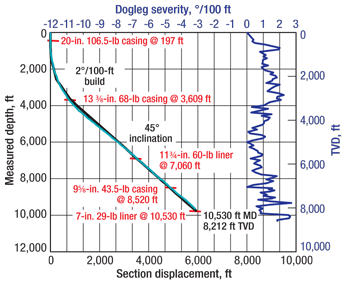
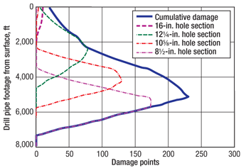
Analysis began on Pag 1004D by creating a pre-drill model using the planned trajectory and planned operational parameters by hole section as supplied by Pluspetrol, Fig. 1. Pre-drill modeling resulted in the projection of accumulated fatigue damage along the 5 7⁄8-in. drill pipe, Fig. 2. Table 1 provides a summary of each well’s TD drillstring configuration. Note that the cumulative fatigue analysis was focused on the 57⁄8-in. drillstring section in all three wells.
 |
|
Fig. 1. The pre-drill model used the planned trajectory for Pag 1004D.
|
|
 |
|
Fig. 2. Pre-drill modeling resulted in a fatigue damage projection for the 5 7⁄8-in. drill pipe.
|
|
| TABLE 1. Pagoreni project drillstrings |
 |
Fatigue damage increases with any increase in dogleg severity, rotational speed and hanging tension, and with a decrease in ROP.1 The highest fatigue accumulation was predicted in drill pipe joints with the most rotations in sections of the wellbore with the highest combination of tension and bending. Typically, a damage band for the initiation of drillstring management is established at or around 500 damage points depending on the confidence in the pipe service history and condition, as well as the criticality of the drilling program.1,5 The particular string of 5 7⁄8-in., 23.4-lb, S-135 drill pipe deployed had a relatively short service life before it was acquired by Pluspetrol. The team established 800 as the damage point threshold. For Pag 1004D, the pre-drill model predicted the maximum fatigue accumulation to occur in the section from 4,188-ft to 5,492-ft MD with a maximum of 227 damage points at 5,166-ft MD (joint 166).
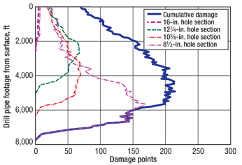
With the pre-drill planning completed, the analysis then moved to real-time monitoring at spud. This stage required close communication between on-site personnel and the office-based engineering support team to track pipe position. The sequence and duration of drilling operations were obtained directly from digital drilling data and cross-referenced to operator, service company and rig contractor daily morning reports, Fig. 3.
 |
|
Fig. 3. The final real-time results after drilling Pag 1004D from spud to TD.
|
|
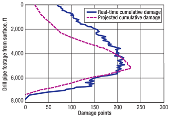
Drilling operations proceeded from spud to TD smoothly and as expected without any significant deviations from expected drilling parameters. A reasonable correlation existed between the cumulative damage real-time results and pre-drill projections, Fig. 4.
 |
|
Fig. 4. A reasonable correlation existed between the real-time cumulative damage results and pre-drill projections.
|
|
Some deviation from anticipated accumulation did occur as a result of deviations between planned and actual operations. Increased circulating and hole conditioning times, predominantly in the 10 5⁄8-in. and 8 1⁄2-in. hole sections, increased the damage observed in the drill pipe footage through 4,000 ft. Higher than expected actual ROP in the 10 5⁄8-in. hole section resulted in real-time cumulative damage slightly lower than modeled from 4,000 ft to 5,500 ft. From about 6,000 ft to 6,800 ft, increased fatigue damage was due to significant (and unplanned) rotation off bottom while drilling the 81⁄2-in. hole section. Even with the observed deviation, the projected damage was a reasonable correlation to the pre-drill model.
PAGORENI 1005D
With Pag 1004D completed successfully, the team’s focus shifted to Pag 1005D. Based on the planned wellbore trajectory and the planned drilling operations, a pre-drill model was created. When the pre-drill model predictions were combined with the real-time model results for Pag 1004D, the cumulative damage was expected to remain safely below the established inspection threshold of 800 damage points.
Therefore, the team decided to forego inspection prior to the spud of Pag 1005D, to re-run 5 7⁄8-in. drill pipe as racked and to monitor real-time accumulation while drilling. Pre-drill analysis projected the first pipe repositioning prior to spud of Pag 1006D. This lead time allowed the team to consider pipe racking strategies for Pag 1006D, even before spudding Pag 1005D.
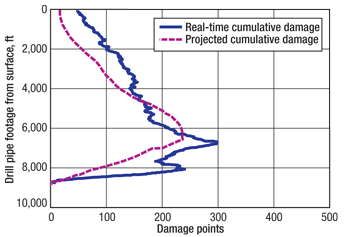
The engineering support team isolated each well’s contributions to the imposed damage without current-well considerations that might mask prior history. This analysis identified two spikes in the cumulative curve vs. the gradual downward slope of the pre-drill fatigue damage projections. The deviation from expected accumulation was due to slightly slower than modeled ROP from about 10,560-ft to 11,460-ft MD (18.1 ft/hr actual average ROP vs. 28.5 ft/hr modeled) as well as a significant increase in hole-cleaning operations (circulating and rotating) when drilling the 8 1⁄2-in. production hole section.
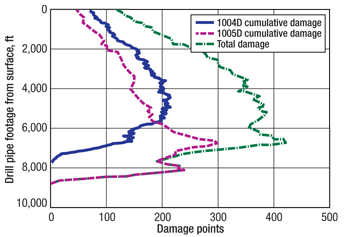
With this anomaly considered, the pre-drill model projection and real-time model accumulation were directly compared, Fig. 5. With spud of Pag 1006D approaching and two wells drilled successfully without pipe inspection, the actual fatigue accumulation from drilling Pag 1004D and Pag 1005D and the pre-drill projected damage accumulation for Pag 1006D were the basis for developing the pipe management strategy, Fig. 6.
 |
|
Fig. 5. The pre-drill model projection and real-time model accumulation for Pag 1005D were directly compared.
|
|
 |
|
Fig. 6. The actual fatigue accumulation curves from Pag 1004D and Pag 1005D were used to develop the pipe management strategy for Pag 1006D.
|
|
The pre-drill projections correlated well with the combined real-time cumulative results of Pag 1004D and Pag 1005D. The projections predicted a maximum of 420 damage points from drilling Pag 1004D and Pag 1005D, while the estimated actual maximum was 421 damage points. Slight shifts in the location along the string where actual damage accumulation resulted, vs. where the damage accumulation was projected, were a result of variations in casing setting depths (i.e., actual TD of each hole section) and actual vs. planned drilling parameters.
PAGORENI 1006D
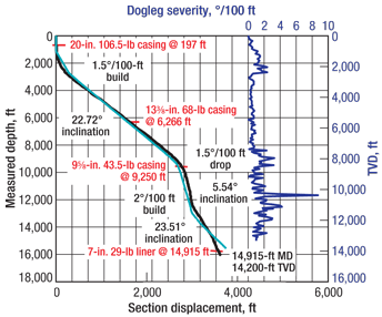
The Pagoreni gas development program maintained very similar well designs on the first five wells. However, Pag 1006D was not only different in its trajectory, but also in its design through the production zone, Fig. 7. All previous wells had traversed the reservoir with an 8 1⁄2-in. hole, while Pag 1006D intersected the reservoir with a 12 1⁄4-in. hole. The 8 1⁄2-in. hole section was reserved for an exploration target 5,700 ft of MD below the development reservoir.
 |
|
Fig. 7. The wellbore trajectory, casing setting depths and dogleg severity for Pag 1006D.
|
|
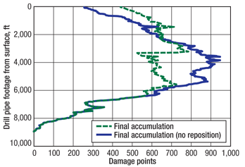
The team continued the established process of fatigue damage mitigation for Pag 1006D. Including the cumulative real-time results from Pag 1004D and Pag 1005D and the pre-drill projection for Pag 1006D, cumulative fatigue damage projections were projected through TD for Pag 1006D. The 5 7⁄8-in., 23.4-lb, S-135 drill pipe would be subjected to the highest level of cumulative fatigue damage and, thus, was the footage most likely to require relocation in the wellbore. Damage accumulation was projected to be just below the 600-damage-point level, if the pipe was deployed as racked.
To more effectively balance fatigue damage across the string and avoid a section of the string with a damage “hot spot,” a section of pipe was identified for repositioning. The repositioning of this pipe section (2,500–5,800-ft MD) reduced the maximum projected fatigue damage to below 500 damage points. This decision was driven largely by the uncertainty of the drilling parameters assumed in the pre-drill model for the 8 1⁄2-in. hole section and by the cost of laying out pipe for inspection mid-well.
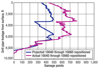
The increase in actual fatigue accumulation to just below the 800-point ceiling from that modeled at just below 500 damage points was due to lower actual ROP than was modeled below 9,000 ft of MD (8,530 ft of TVD) in the formation intervals not previously drilled, Fig. 8. The reduced ROP was due to directional control issues, challenges with BHA stick-slip and vibration mitigation while drilling hard formations.
 |
|
Fig. 8. The increase in actual fatigue accumulation was due to lower than anticipated ROP below 9,000 ft of MD in the formation intervals not previously drilled.
|
|
Despite the increased damage while drilling the 8 1⁄2-in. hole section, the pre-spud decision to reposition the pipe and to closely monitor real-time fatigue accumulation using as-drilled operations allowed Pluspetrol to reach TD with damage point levels maintained slightly below the 800-damage-point ceiling set for the 5 7⁄8-in., 23.4-lb, S-135 drill pipe prior to the spud of Pag 1004D. This was accomplished with a single pipe-section relocation in the last of the three wells and required no mid-well or mid-program inspections.
INSPECTION RESULTS
One of the most critical factors required to minimize drill pipe fatigue failures is implementation of a properly defined and correctly executed drill pipe inspection program. Pluspetrol acquired a string of 5 7⁄8-in., 23.4-lb, S135, XT-57 drill pipe used previously in Canada to drill a single well. Prior to delivery to Pluspetrol, the pipe had undergone a Standard DS-1 Category 4 inspection in Newfoundland, Canada.5
Pluspetrol elected to perform a second inspection of 35 joints after their arrival at its Malvinas base. This inspection was performed to Standard DS-1 Category 5; the slip and upset areas were inspected using the ultrasonic slip/upset method, and the tool joints were inspected using the blacklight connection method.5 A crack was found in the slip/upset area of one of the sample joints, so the company decided to have the balance of the drill pipe inspected to Standard DS-1 Category 5 minus EMI 1.5 Pluspetrol elected to omit EMI 1 inspection, since the pipe was essentially “new” and the slip and upset area would be covered using shear-wave ultrasonic.
The pre-spud inspection found several repairable mechanical damages, a single repairable (re-cut) cracked box tool joint, a non-repairable transverse fatigue crack in the slip/upset area of one joint and a slip cut that exceeded 10% of the adjacent wall (0.044-in. depth). The pre-spud inspection performed in Malvinas provided the necessary confidence that no pipe was being deployed with detectable pre-existing transverse fatigue flaws in the drill pipe tube body or the slip/upset area.
Upon completion of Pag 1006D, the entire string of 5 7⁄8-in. drill pipe was again inspected to Standard DS-1 Category 5. No fatigue flaws were detected in the 5 7⁄8-in., 23.4-lb, S-135 drill pipe tube body or slip/upset areas. These results were consistent with the expectations from the three well cumulative fatigue damage assessments. The inspection results supported the results of the analyses, and the approach was considered successful, as mid-well and/or mid-program inspections were avoided and fatigue failures were mitigated using one carefully engineered and forecast pipe repositioning.
The post-drill inspection results identified significant mechanical damage and one cracked box-tool joint. The box crack was correlated back to joint 194, represented by drill pipe footage at or near 6,000 ft with cumulative fatigue estimated at 606 damage points, Fig. 9. While the cumulative fatigue approach is designed to assess crack propagation in drill pipe tubes and not in the tool joints, it is critical to correlate all fatigue cracks to the model results and apply a risk factor to the joints surrounding cracked joints. The majority of damage was associated with handling/stabbing, which provided feedback and guidance on best practices.
 |
|
Fig. 9. A box crack was correlated back to joint 194, which was drill pipe footage at or near 6,000 ft.
|
|
Because the post-drill inspection did not find detectable damage in the drill pipe tubes, the damage points will be reset to zero for the next drilling campaign. This “re-zeroing” is based on the assumption that a preexisting crack of known length exists within the drill pipe tube, but it is too small for detection.1 Due to the project’s success, the approach will be continued over three years on the operator’s next 10 wells.
CONCLUSIONS
The cumulative fatigue damage method approximates the fatigue level within the string and allows the operator to intelligently manage pipe deployment and inspection frequency. Cooperation among the operator, drilling contractor and service company support personnel in executing an engineered approach to fatigue mitigation resulted in no drill pipe fatigue-related failures, no unnecessary inspections and one planned drill pipe repositioning. The program requires a thorough and well-controlled drill pipe inspection prior to initiation to ensure that existing cracks are smaller than a detectable size using current equipment and best practice application.
In the case study, re-inspection immediately before project initiation identified significant mechanical damage, one repairable box crack, one joint with a crack in the pipe slip/upset area and one joint with a rejectable slip cut. Specific pipe section footage could not be easily identified for relocation and risk mitigation without using the method described. In addition to eliminating inspection costs, Pluspetrol eliminated costly rig time from pipe lay-down/pickup and remote location transportation/logistics which the operator estimated at several hundreds of thousands of dollars. 
ACKNOWLEDGMENTS
The authors thank Pluspetrol Peru Corp. for permission to publish this article. The authors are grateful for the assistance of Stanley Barrett, Consultant Drilling Supervisor, for his support, contributions to the text and manuscript review. The authors are also indebted to Joel Wesevich and Al Cunningham, T H Hill QA/QC Technicians, for their field support and manuscript review. This article was prepared from SPE/IADC 119903, which was presented at the SPE/IADC Drilling Conference and Exhibition held in Amsterdam, the Netherlands, March 17–19, 2009.
LITERATURE CITED
1 Gokhale, S., Zoanni, R., Zheng, N. and D. Everage, “Advances in drill pipe fatigue management,” SPE 110076, 2007.
2 Clark, J., Reynolds, N., Ellis, S. and J. Stuart, “Advances in fatigue design: Curvature index theory and case study,” World Oil, October 2003, p. 29.
3 Hill, T. H., Ellis, S., Lee, K., Reynolds, N. and N. Zheng, “An innovative design approach to reduce drillstring fatigue,” SPE/IADC 87188, 2004.
4 Bert, D. R., Storaune, A., N. Zheng, “Case study: Drillstring failure analysis and new deep-well guidelines lead to success,” SPE 110708, 2007.
5 T. H. Hill Associates, Inc., DS-1 Drill Stem Inspection, Vol. 3, 3rd Ed., January 2004.
|
THE AUTHORS
|
 |
Richard F. Zoanni is a Senior Drilling and Completions Consultant with T H Hill Associates, Inc. He earned his BS degree in mechanical engineering from Montana Tech. He worked in technical support, tool design and field implementation for Smith International and National Oilwell Varco prior to joining T H Hill. He conducts drill pipe fatigue analysis and fatigue damage monitoring for well programs in the Americas, specializing in mechanical failure analysis, drilling and completions.
|
|
| |
S. DeWayne Everage is Vice President of Technical Services for T H Hill Associates, Inc., based in Houston. He earned a BS (honors) degree in mechanical engineering from the University of Florida. He began his career with Exxon, drilling and completing GOM horizontal and highly deviated extended-reach wells before taking a position with T H Hill in 1998. His career has been dedicated to oil and gas drilling tubular design, failure mitigation and tubular quality assurance.
|
|
| |
Thomas M. (Tom) Wadsworth is President of T H Hill Associates, Inc. He earned a BS degree in mechanical engineering from Texas A&M University. Prior to joining T H Hill in 2000, he held various management and technical positions including Division Manager with Fina Oil and Chemical Co., Drilling Manager with two independents and Senior Supervisor with Exxon.
|
|
| |
Juan P. Cassanelli is the Worldwide Drilling Manager for Pluspetrol Corporation S.A. He earned a BS degree in chemical engineering with postgraduate studies in oil and gas production from Universidad Nacional de Buenos Aires. He has 27 years of drilling experience with major emphasis in deep, directional, HPHT and horizontal projects. For the last eight years he has been Drilling Manager for the Camisea Gas Development Project.
|
|


